EP0333640B1 - Soupape de retenue avec dispositif d'étranglement - Google Patents
Soupape de retenue avec dispositif d'étranglement Download PDFInfo
- Publication number
- EP0333640B1 EP0333640B1 EP89810010A EP89810010A EP0333640B1 EP 0333640 B1 EP0333640 B1 EP 0333640B1 EP 89810010 A EP89810010 A EP 89810010A EP 89810010 A EP89810010 A EP 89810010A EP 0333640 B1 EP0333640 B1 EP 0333640B1
- Authority
- EP
- European Patent Office
- Prior art keywords
- valve
- bore
- valve device
- housing
- throttle
- Prior art date
- Legal status (The legal status is an assumption and is not a legal conclusion. Google has not performed a legal analysis and makes no representation as to the accuracy of the status listed.)
- Expired - Lifetime
Links
- 238000010586 diagram Methods 0.000 claims abstract description 9
- 238000010276 construction Methods 0.000 description 5
- 238000004519 manufacturing process Methods 0.000 description 3
- 238000007789 sealing Methods 0.000 description 3
- 238000003801 milling Methods 0.000 description 2
- 230000032683 aging Effects 0.000 description 1
- 230000000903 blocking effect Effects 0.000 description 1
- 230000000694 effects Effects 0.000 description 1
- 239000013536 elastomeric material Substances 0.000 description 1
- 238000012423 maintenance Methods 0.000 description 1
- 210000000056 organ Anatomy 0.000 description 1
- 238000007650 screen-printing Methods 0.000 description 1
Images

Classifications
-
- F—MECHANICAL ENGINEERING; LIGHTING; HEATING; WEAPONS; BLASTING
- F16—ENGINEERING ELEMENTS AND UNITS; GENERAL MEASURES FOR PRODUCING AND MAINTAINING EFFECTIVE FUNCTIONING OF MACHINES OR INSTALLATIONS; THERMAL INSULATION IN GENERAL
- F16K—VALVES; TAPS; COCKS; ACTUATING-FLOATS; DEVICES FOR VENTING OR AERATING
- F16K47/00—Means in valves for absorbing fluid energy
- F16K47/08—Means in valves for absorbing fluid energy for decreasing pressure or noise level and having a throttling member separate from the closure member, e.g. screens, slots, labyrinths
- F16K47/10—Means in valves for absorbing fluid energy for decreasing pressure or noise level and having a throttling member separate from the closure member, e.g. screens, slots, labyrinths in which the medium in one direction must flow through the throttling channel, and in the other direction may flow through a much wider channel parallel to the throttling channel
-
- F—MECHANICAL ENGINEERING; LIGHTING; HEATING; WEAPONS; BLASTING
- F16—ENGINEERING ELEMENTS AND UNITS; GENERAL MEASURES FOR PRODUCING AND MAINTAINING EFFECTIVE FUNCTIONING OF MACHINES OR INSTALLATIONS; THERMAL INSULATION IN GENERAL
- F16K—VALVES; TAPS; COCKS; ACTUATING-FLOATS; DEVICES FOR VENTING OR AERATING
- F16K15/00—Check valves
- F16K15/18—Check valves with actuating mechanism; Combined check valves and actuated valves
- F16K15/184—Combined check valves and actuated valves
- F16K15/1848—Check valves combined with valves having a rotating tap or cock
Definitions
- Such a valve device is commercially available. It is designed as a screw connection, so that it can be used for a cylinder instead of the swivel screw connection, for example.
- a flexible ring sleeve takes over the function of the check valve.
- the supply air pushes the ring sleeve apart, as a result of which the flow opening is fully unblocked.
- the flexible ring sleeve With a flow in the direction away from the cylinder, the flexible ring sleeve is pressed inwards against a perforated sleeve. This closes the full flow opening and the exhaust air is directed via an adjustable throttle. So there is an exhaust air throttling.
- Valves with flexible ring sleeves are known to be temperature sensitive.
- the ring sleeve becomes stiff at low temperatures.
- Ring cuffs are also subject to a certain aging. They can become brittle and tear after a certain time.
- the known valve device has a relatively small flow cross section.
- valve device it is therefore an object of the present invention to further develop the generic valve device. It should also be possible to use it as a swivel screw connection. If possible, the valve device should be usable both for exhaust air and supply air throttling or even as a bare throttle. In the latter case, it would also be desirable if it was clearly visible from the outside which function was set.
- the check valve is arranged in a third hole in the valve housing, which communicates with both holes.
- This arrangement has the advantage that, despite the design of the valve device as a screw connection, the flow cross-section is not excessively limited by the nominal size of the screw connection. Nevertheless, the valve device is very simple and compact in construction. It is therefore very well suited for placement on a pneumatic cylinder. This has the advantage that, in the case of a machine, it is immediately apparent which organ of the machine the valve device belongs to. This contributes to security. There is then no risk that a valve will be confused with another valve during maintenance work, as is easily the case if several valves are arranged on a directional control valve and the line routing to the different cylinders is not clearly visible.
- the third bore is advantageously arranged such that it cuts the first and / or second bore. This has the advantage that no special milling operations are necessary during production in order to create the necessary passages between the bores.
- a diagram is advantageously provided on the outside of the valve device. Part of the diagram can be arranged on the valve housing and another part on the outside of the valve carrier. This has the advantage that when the valve carrier is adjusted, a change in the scheme is also inevitably effected. So you can see at a glance at the valve whether it works with supply or exhaust air throttling or as a bare throttle.
- valve carrier expediently has a groove at each end, in which a sealing ring is arranged. No special sealing measures are then necessary. Rather, it suffices to insert the valve carrier with the check valve arranged thereon into the valve housing in order to bring about the necessary seal for the check valve to the outside.
- the movable valve member is advantageously mounted transversely to the third bore and is biased by at least one spring against the wall of the third bore. This results in a very simple construction of the check valve.
- valve device provides that one end of the connecting member is replaced by a polygon, e.g. Hexagon is formed, which is arranged on one side of the valve housing, and that the other end of the connecting member is formed by a threaded piece which protrudes from the valve housing on the other side.
- a polygon e.g. Hexagon is formed
- the other end of the connecting member is formed by a threaded piece which protrudes from the valve housing on the other side.
- the section of the connecting member located in the valve housing advantageously has two constrictions in order to form two ring channels in the first bore, which can communicate with the second or the third bore. This results in a very simple construction.
- the connecting link can be produced as a Vietnamese tank.
- a seal is provided on the connecting element in the polygon, between the two ring channels and in the threaded piece.
- the first two seals are expediently O-rings made of elastomeric material, which are very cheap.
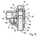
- the valve device has a valve housing 11. Bores 13 and 15 arranged at right angles to one another are provided in this.
- the bore 13 serves to receive a connecting member 17.
- the bore 15 has a thread 19 which is used to connect a line.
- a recess in the form of a further third bore 21 is arranged.
- a passage 27 leads to the bore 15 and a passage 29 to the bore 13.
- the bore 21 can therefore communicate with both bores 15 and 13 in the valve housing.
- the connecting member 17 consists of a Vietnameselletage part and has a hexagon 31 at one end.
- the other end of the connecting member 17, which protrudes from the valve housing 11, is formed by a threaded piece 33.
- the illustrated embodiment of the valve device thus also represents a swivel screw connection.
- the section of the connecting member 17 located within the valve housing 11 has two constrictions 35, 37 which each form an annular channel within the valve housing.
- a coaxial bore 39 is arranged in the connecting member 17.
- the bore 39 communicates with the annular channels 35 and 37 via transverse bores 41, 43.
- the bore 39 has a section 45 with an enlarged diameter in the upper part. Adjoining this section 45 is a threaded section 47.
- a throttle screw 49 is screwed into this threaded section to a greater or lesser extent in order to cover the transverse bore 41 to a greater or lesser extent, in order to effect a more or less severe throttling or blocking.
- the throttle screw 49 is provided with an O-ring seal 51.
- O-ring seals 52 and 53 are provided in the vicinity of hexagon 31 and between the two ring channels 35, 37.
- a seal 55 is also found on the threaded piece 33.
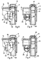
- the check valve 25 is arranged on a valve support 23.
- the check valve 25 has a valve member 57 which is movable transversely to the bore 21 and is biased by a spring 59 against the wall of the bore 21. As FIG. 2 shows, the passage 27 to the bore 15 is closed.
- the valve carrier 23 also has the task of sealing both ends of the bore 21.
- the valve carrier 23 has a groove 61 at each end into which an O-ring 63 is inserted (FIGS. 3 and 4).
- the valve member 57 has a projection 65 on two opposite sides. Each projection 65 runs in a guide 67 in the valve carrier 23.
- FIGS. 5 and 6 Another embodiment of the valve carrier 23 is shown in FIGS. 5 and 6. Again, a groove 61 is provided at both ends of the valve carrier 23, in which an O-ring 63 is embedded. Outside the area of the passage 27 (Fig. 2), the valve member 57 has a bore 65 'at each of its ends. To guide the valve member 57 serve guide pins 67 'which are fixed in the valve carrier 23. The guide pins 67 'also serve to receive the coil springs 59, which endeavor to press the valve member 57 against the passage 27 to close it (Fig. 2).
- the valve device of Figures 1 and 2 causes exhaust air throttling.
- the throttle screw 49 is completely throttled.
- the throttle screw 49 is not screwed in as deep as shown in FIG. 1, so that, for example, exhaust air from a cylinder through the bore 39 and then past the throttle screw 49 into the transverse bore 41 and from there into the annular channel 45 and Bore 15 can flow (Fig. 2).
- a cylinder is to be acted upon, the supply air flows through the bore 15 into the passage 27 and presses the valve member 57 into the position shown in broken lines.
- the air then flows from the bore 21 through the passage 29 into the ring channel 37 and the transverse bore 43 into the bore 39.
- the cross sections of the various bores and passages are large. These cross sections are much larger than in the known throttle check valves designed as screw connections.
- a slot 69 is formed on the valve support 23, with which the valve support 23 can be rotated in the bore 21.
- the valve support 23 can be in three different positions with a locking member, e.g. a screw 71 can be secured.
- the screw 71 engages in one of the cutouts 73 in the valve carrier 23.
- valve carrier 23 renders the valve 25 ineffective, so that the valve device only works as a throttle.
- a scheme 75 is attached on one or both sides, e.g. printed by screen printing.
- a part of the diagram 75 is located on the valve housing 11 and another part on the outside of the valve carrier 23.
- An adjustment of the valve carrier 23 therefore inevitably also causes a diagram change.
- Scheme 75 of FIG. 1 thus shows that if the valve device is screwed onto a cylinder with the thread 33, exhaust air throttling is used.
- the scheme 75 of FIG. 8 shows the use for supply air throttling and the scheme of FIG. 10 shows the use for supply and exhaust air throttling.
- the embodiment of the valve device of Fig. 12 is basically the same as that previously described. However, the hole 21 is arranged so that it intersects the holes 13 and 15. In this embodiment of the valve housing 11, the passages are already created during the production of the bores 13, 15 and 21, which have to be produced in the valve housing 11 of FIG. 2 by special manufacturing operations (e.g. millings 27, 29 in FIG. 2). In the valve housing of FIG. 12, however, it must be ensured that the thread 19 does not extend into the area of the valve member 57.
Landscapes
- Engineering & Computer Science (AREA)
- General Engineering & Computer Science (AREA)
- Mechanical Engineering (AREA)
- Check Valves (AREA)
- Control Of Throttle Valves Provided In The Intake System Or In The Exhaust System (AREA)
Claims (15)
Priority Applications (1)
| Application Number | Priority Date | Filing Date | Title |
|---|---|---|---|
| AT89810010T ATE65306T1 (de) | 1988-01-11 | 1989-01-09 | Mit einer drosselvorrichtung versehenes rueckschlagventil. |
Applications Claiming Priority (2)
| Application Number | Priority Date | Filing Date | Title |
|---|---|---|---|
| CH7088 | 1988-01-11 | ||
| CH70/88 | 1988-01-11 |
Publications (2)
| Publication Number | Publication Date |
|---|---|
| EP0333640A1 EP0333640A1 (fr) | 1989-09-20 |
| EP0333640B1 true EP0333640B1 (fr) | 1991-07-17 |
Family
ID=4178610
Family Applications (1)
| Application Number | Title | Priority Date | Filing Date |
|---|---|---|---|
| EP89810010A Expired - Lifetime EP0333640B1 (fr) | 1988-01-11 | 1989-01-09 | Soupape de retenue avec dispositif d'étranglement |
Country Status (3)
| Country | Link |
|---|---|
| EP (1) | EP0333640B1 (fr) |
| AT (1) | ATE65306T1 (fr) |
| DE (1) | DE58900172D1 (fr) |
Families Citing this family (1)
| Publication number | Priority date | Publication date | Assignee | Title |
|---|---|---|---|---|
| DE29508395U1 (de) * | 1995-05-19 | 1995-08-10 | Heilmeier & Weinlein Fabrik für Oel-Hydraulik GmbH & Co KG, 81673 München | Hydraulisches Dämpfungsventil |
Family Cites Families (2)
| Publication number | Priority date | Publication date | Assignee | Title |
|---|---|---|---|---|
| SE389185B (sv) * | 1974-02-08 | 1976-10-25 | Vadstena Pumpar Ab | For centralvermeanleggningar avsett shuntaggregat |
| CH580715A5 (fr) * | 1974-04-18 | 1976-10-15 | Reber Martin |
-
1989
- 1989-01-09 EP EP89810010A patent/EP0333640B1/fr not_active Expired - Lifetime
- 1989-01-09 AT AT89810010T patent/ATE65306T1/de not_active IP Right Cessation
- 1989-01-09 DE DE8989810010T patent/DE58900172D1/de not_active Expired - Fee Related
Non-Patent Citations (1)
| Title |
|---|
| Prospekt eines im Handel befindlichen und bekannten Drossel- Rückschlagventils * |
Also Published As
| Publication number | Publication date |
|---|---|
| ATE65306T1 (de) | 1991-08-15 |
| DE58900172D1 (de) | 1991-08-22 |
| EP0333640A1 (fr) | 1989-09-20 |
Similar Documents
| Publication | Publication Date | Title |
|---|---|---|
| DE69123764T2 (de) | Vorrichtung für endlagedämpfung und geschwindigkeitsregelung der bewegung eines kolbens in einem druckmittelzylinder | |
| EP0599432A1 (fr) | Soupape de retenue avec dispositif d'étranglement | |
| DE19537482A1 (de) | Hydraulischer Steuerblock | |
| EP0868619B1 (fr) | Dispositif de commande pour soupape a double siege | |
| DE102010048068B4 (de) | Ventilanordnung | |
| EP0061415A1 (fr) | Soupape pour systèmes hydrauliques | |
| DE19602796B4 (de) | Steuerventil für kleinen Durchfluß | |
| DE69908625T2 (de) | Rückschlagventil | |
| DE2707134A1 (de) | Vorrichtung zur durchflussregelung | |
| DE3115661A1 (de) | Einrichtung zur regelung von druck und durchsatz an mit druckgas betriebenen geraeten | |
| DE69210232T2 (de) | Modulares wegeventil | |
| DE2008092C3 (de) | Ventileinrichtung zur hydraulischen Blockierung | |
| DE8324276U1 (de) | Drosselvorrichtung | |
| EP0333640B1 (fr) | Soupape de retenue avec dispositif d'étranglement | |
| DE2650803A1 (de) | Ventil | |
| DE3239930A1 (de) | Hydraulisch steuerbares sperrventil, insbesondere fuer die rohrbruchsicherung | |
| DE2237239C3 (de) | Bohrstrangventil | |
| DE1282379B (de) | Ventil | |
| DE2750956A1 (de) | Thermostat-ventil | |
| DE3828025A1 (de) | Daempfungssystem fuer fluid-zylinder | |
| DE3520745A1 (de) | Vorrichtung zur schaltzeiteinstellung eines ventilgliedes | |
| DE3337426C2 (fr) | ||
| DE3830476C2 (fr) | ||
| DE3740001C2 (de) | Vorrichtung zur Steuerung eines Stromes einer Flüssigkeit zwischen einem Zuführungskanal bzw. einem Abführungskanal und einem Arbeitskanal | |
| DE2012816C3 (de) | Aus mehreren Einzelelementen bestehende Sammelanschluß-Tragplatte |
Legal Events
| Date | Code | Title | Description |
|---|---|---|---|
| PUAI | Public reference made under article 153(3) epc to a published international application that has entered the european phase |
Free format text: ORIGINAL CODE: 0009012 |
|
| AK | Designated contracting states |
Kind code of ref document: A1 Designated state(s): AT CH DE ES FR GB IT LI NL SE |
|
| 17P | Request for examination filed |
Effective date: 19900309 |
|
| 17Q | First examination report despatched |
Effective date: 19900627 |
|
| GRAA | (expected) grant |
Free format text: ORIGINAL CODE: 0009210 |
|
| AK | Designated contracting states |
Kind code of ref document: B1 Designated state(s): AT CH DE ES FR GB IT LI NL SE |
|
| PG25 | Lapsed in a contracting state [announced via postgrant information from national office to epo] |
Ref country code: NL Effective date: 19910717 Ref country code: GB Effective date: 19910717 Ref country code: ES Free format text: THE PATENT HAS BEEN ANNULLED BY A DECISION OF A NATIONAL AUTHORITY Effective date: 19910717 |
|
| REF | Corresponds to: |
Ref document number: 65306 Country of ref document: AT Date of ref document: 19910815 Kind code of ref document: T |
|
| ITF | It: translation for a ep patent filed | ||
| REF | Corresponds to: |
Ref document number: 58900172 Country of ref document: DE Date of ref document: 19910822 |
|
| ET | Fr: translation filed | ||
| NLV1 | Nl: lapsed or annulled due to failure to fulfill the requirements of art. 29p and 29m of the patents act | ||
| GBV | Gb: ep patent (uk) treated as always having been void in accordance with gb section 77(7)/1977 [no translation filed] | ||
| PLBE | No opposition filed within time limit |
Free format text: ORIGINAL CODE: 0009261 |
|
| STAA | Information on the status of an ep patent application or granted ep patent |
Free format text: STATUS: NO OPPOSITION FILED WITHIN TIME LIMIT |
|
| 26N | No opposition filed | ||
| PGFP | Annual fee paid to national office [announced via postgrant information from national office to epo] |
Ref country code: FR Payment date: 19931208 Year of fee payment: 6 |
|
| PGFP | Annual fee paid to national office [announced via postgrant information from national office to epo] |
Ref country code: AT Payment date: 19931213 Year of fee payment: 6 |
|
| PGFP | Annual fee paid to national office [announced via postgrant information from national office to epo] |
Ref country code: SE Payment date: 19931214 Year of fee payment: 6 |
|
| PGFP | Annual fee paid to national office [announced via postgrant information from national office to epo] |
Ref country code: CH Payment date: 19931217 Year of fee payment: 6 |
|
| REG | Reference to a national code |
Ref country code: CH Ref legal event code: PFA Free format text: PRESS CONTROLS AG RUEMLANG |
|
| PGFP | Annual fee paid to national office [announced via postgrant information from national office to epo] |
Ref country code: DE Payment date: 19940324 Year of fee payment: 6 |
|
| REG | Reference to a national code |
Ref country code: FR Ref legal event code: CD Ref country code: FR Ref legal event code: CA |
|
| PG25 | Lapsed in a contracting state [announced via postgrant information from national office to epo] |
Ref country code: AT Effective date: 19950109 |
|
| PG25 | Lapsed in a contracting state [announced via postgrant information from national office to epo] |
Ref country code: SE Effective date: 19950110 |
|
| EAL | Se: european patent in force in sweden |
Ref document number: 89810010.2 |
|
| PG25 | Lapsed in a contracting state [announced via postgrant information from national office to epo] |
Ref country code: LI Effective date: 19950131 Ref country code: CH Effective date: 19950131 |
|
| PG25 | Lapsed in a contracting state [announced via postgrant information from national office to epo] |
Ref country code: FR Effective date: 19950929 |
|
| REG | Reference to a national code |
Ref country code: CH Ref legal event code: PL |
|
| PG25 | Lapsed in a contracting state [announced via postgrant information from national office to epo] |
Ref country code: DE Effective date: 19951003 |
|
| EUG | Se: european patent has lapsed |
Ref document number: 89810010.2 |
|
| REG | Reference to a national code |
Ref country code: FR Ref legal event code: ST |
|
| PG25 | Lapsed in a contracting state [announced via postgrant information from national office to epo] |
Ref country code: IT Free format text: LAPSE BECAUSE OF NON-PAYMENT OF DUE FEES;WARNING: LAPSES OF ITALIAN PATENTS WITH EFFECTIVE DATE BEFORE 2007 MAY HAVE OCCURRED AT ANY TIME BEFORE 2007. THE CORRECT EFFECTIVE DATE MAY BE DIFFERENT FROM THE ONE RECORDED. Effective date: 20050109 |