EP0333609A1 - Automatische Verfahren und Vorrichtungen zum Schreiben hochaufgelöster Schriftzeichen auf ein Objekt durch Ausstoss farbiger Flüssigkeitströpfchen - Google Patents
Automatische Verfahren und Vorrichtungen zum Schreiben hochaufgelöster Schriftzeichen auf ein Objekt durch Ausstoss farbiger Flüssigkeitströpfchen Download PDFInfo
- Publication number
- EP0333609A1 EP0333609A1 EP89430004A EP89430004A EP0333609A1 EP 0333609 A1 EP0333609 A1 EP 0333609A1 EP 89430004 A EP89430004 A EP 89430004A EP 89430004 A EP89430004 A EP 89430004A EP 0333609 A1 EP0333609 A1 EP 0333609A1
- Authority
- EP
- European Patent Office
- Prior art keywords
- substrate
- axis
- along
- tool holder
- nozzle
- Prior art date
- Legal status (The legal status is an assumption and is not a legal conclusion. Google has not performed a legal analysis and makes no representation as to the accuracy of the status listed.)
- Withdrawn
Links
Images


Classifications
-
- B—PERFORMING OPERATIONS; TRANSPORTING
- B41—PRINTING; LINING MACHINES; TYPEWRITERS; STAMPS
- B41J—TYPEWRITERS; SELECTIVE PRINTING MECHANISMS, i.e. MECHANISMS PRINTING OTHERWISE THAN FROM A FORME; CORRECTION OF TYPOGRAPHICAL ERRORS
- B41J2/00—Typewriters or selective printing mechanisms characterised by the printing or marking process for which they are designed
- B41J2/005—Typewriters or selective printing mechanisms characterised by the printing or marking process for which they are designed characterised by bringing liquid or particles selectively into contact with a printing material
- B41J2/01—Ink jet
- B41J2/21—Ink jet for multi-colour printing
- B41J2/2103—Features not dealing with the colouring process per se, e.g. construction of printers or heads, driving circuit adaptations
-
- B—PERFORMING OPERATIONS; TRANSPORTING
- B41—PRINTING; LINING MACHINES; TYPEWRITERS; STAMPS
- B41J—TYPEWRITERS; SELECTIVE PRINTING MECHANISMS, i.e. MECHANISMS PRINTING OTHERWISE THAN FROM A FORME; CORRECTION OF TYPOGRAPHICAL ERRORS
- B41J11/00—Devices or arrangements of selective printing mechanisms, e.g. ink-jet printers or thermal printers, for supporting or handling copy material in sheet or web form
- B41J11/001—Handling wide copy materials
-
- B—PERFORMING OPERATIONS; TRANSPORTING
- B41—PRINTING; LINING MACHINES; TYPEWRITERS; STAMPS
- B41J—TYPEWRITERS; SELECTIVE PRINTING MECHANISMS, i.e. MECHANISMS PRINTING OTHERWISE THAN FROM A FORME; CORRECTION OF TYPOGRAPHICAL ERRORS
- B41J2/00—Typewriters or selective printing mechanisms characterised by the printing or marking process for which they are designed
- B41J2/005—Typewriters or selective printing mechanisms characterised by the printing or marking process for which they are designed characterised by bringing liquid or particles selectively into contact with a printing material
- B41J2/01—Ink jet
Definitions
- the present invention relates to automatic methods and devices for writing high-resolution graphics on a substrate by spraying droplets of colored liquids.
- the technical sector of the invention is that of the construction of automatic machines or robots intended to draw various graphics on various substrates or supports.
- An application of the methods and devices according to the invention is the production in series of flat panels carrying inscriptions and / or drawings or graphics, for example advertising panels, posters, signboards, decorative or advertising patterns on various substrates, packaging, etc.
- the methods and devices according to the invention also make it possible to automatically write graphics on substrates having a surface with a low curvature, for example on car bodies, on curved panels, on various industrial products, on curved walls.
- the colored liquids which can be used on the devices according to the invention can be paints, inks or any other liquid vehicle containing a dye.
- the robots according to the invention make it possible to write letters, numbers or polychrome graphics which are produced by projection of droplets of colored liquid which produce very small and very close colored points, so that a very good result is obtained. resolution and that the eye does not perceive any discontinuity in the graphics.
- the substrates of various composition intended to carry high resolution graphics must comprise one or more sub-layers called sheets. These sublayers ensure the protection of the substrate and the quality of the graphics.
- ink jet computer printers which include an ink projection nozzle equipped with a piezoelectric ceramic which makes it possible to split the ink jet into droplets.
- painting robots which include a spray gun supported by an articulated arm which makes it possible to apply layers of paint on a support.
- the methods and devices according to the invention combine in a new way a part of the techniques for projecting liquid droplets used in inkjet printers and a part of the techniques used in plotters to obtain a relative displacement of the substrate with respect to to the registration tool.
- the publication FR A 2 601 265 (Cherubin-Grillo) describes a device for printing point by point a polychrome image on a fixed substrate which comprises a projection head, movable along three rectangular axes, which carries several nozzles whose axes converge in a point close to the substrate. Each nozzle projects a liquid of a specific color and the colors mix.
- the movements of the projection head are controlled by signals resulting from information recorded in a microprocessor.
- An objective of the present invention is to provide means making it possible to automatically produce, in series and at one time, high resolution graphics composed of very small and very close colored dots.
- Another objective of the invention is to provide an automatic machine or robot which includes means making it possible to create on a screen a graphic to be produced which may be polychrome and to automatically reproduce this graphic on a substrate which may or may not be planar.
- Another object of the invention is to provide a machine capable of automatically reproducing on various substrates, an existing graphics, by enlarging or reducing it or possibly modifying it, respecting or modifying the colors.
- Another objective of the invention is to provide a graphics writing robot which includes means making it possible to automatically control the correct execution of the graphics so as not to harm the high resolution qualities thereof.
- the objectives of the invention are achieved by means of a method which comprises the following sequence of operations: - Several nozzles are mounted, each projecting a liquid of a determined color onto a tool holder which is placed in front of said substrate and which is movable along three rectangular axes, one of which is perpendicular to said substrate and is controlled automatically the movements of said tool holder by an electronic central unit so that each outlet of a nozzle scans line by line a surface parallel to said substrate, which nozzles are perpendicular to said substrate and parallel to each other and are offset in the direction perpendicular to the scanning lines so that they scan different lines, the coordinates of a network of graphic points and the color of each point are recorded in the memory of said central unit and during the movements of the carriage the successive real positions of each nozzle, they are compared with the coordinates recorded in the memory and when the real position of a nozzle which projects a liquid of a determined color coincides with the coordinates of a point of the graphics of this same color l ' central unit controls the
- a device comprises a tool holder which can be moved by servomotors along three rectangular axes, one of which is perpendicular to said substrate, which tool holder carries nozzles for projecting colored liquids of different colors and a unit electronic control unit which automatically controls said servo motors to move said tool holder in front of said substrate along parallel scanning lines and which controls the projection of colored liquid by said nozzles, and said tool holder carries several tools each equipped with one or more several parallel nozzles which are offset from each other in the direction-perpendicular to the scanning lines.
- a device comprises a horizontal rail along which a vertical rail is moved by a first servo motor, along a first axis (YY ′) parallel to said substrate and a carriage which is moved the along said vertical rail by a second servo motor along a second axis (ZZ ′) parallel to said substrate and a tool holder which is mounted on said carriage and which is moved by a third servo motor along a third are (XX ′) perpendicular to said substrate in which said horizontal rail consists of one side of a frame rigid rectangular fixed placed in front of said substrate and said vertical rail is moved inside said frame.
- the invention results in the possibility of automatically inscribing on various substrates graphics which consist of very fine points and very close together and which therefore have a high resolution.
- the invention also results in automatic machines or robots which can be programmed to produce the same graphics in series on a plurality of substrates.
- the methods and machines according to the invention make it possible to produce dot graphics which consist of small juxtaposed spots of colored liquid. They allow you to execute graphics in several colors at once.
- the machines according to the invention are equipped with sensors for real positioning of the tools and with electronic comparison means which at all times compare the real position measured with the theoretical position controlled by the central unit.
- a machine according to the invention is provided with a computer-assisted image creation unit and it makes it possible to reproduce automatically and in series on various substrates a graphic created on the screen of the image creation unit.
- a machine comprises a probe or any other equivalent means of shape analysis which is moved in front of a curved substrate which it scans line by line. It allows the surface shape of a curved substrate to be noted beforehand and the tools to be moved automatically, so that the outlet orifices of the nozzles for spraying colored liquids remain at constant distance from the substrate despite the curvature of the latter. and that the nozzles are constantly perpendicular to the surface of the substrate, so that the colored dots projected on the substrate retain the same dimensions.
- a machine according to the invention can include an electronic memory making it possible to store the data necessary for the automatic reproduction of a graphic design.
- This data can be stored in peripheral memories (floppy disks, discs), which allow the same graphic to be reproduced several times automatically on the same machine or on several machines.
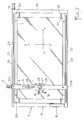
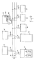
- FIG. 1 represents an overall perspective view of an automatic machine according to the invention, intended for automatically writing a polychrome graphics on a substrate 1, which is for example a vertical plane panel engaged in two vertical slides 2a and 2b.
- the machine comprises a fixed rectangular vertical frame 3 which acts as a work table and which is parallel to the plane defined by the two slides 2a, 2b.
- Frame 3 is mounted on a base or fixed frame 4 which has two guides or guide rods 5 perpendicular to the plane of the frame.
- a mobile support 6 slides on the slides 5. It is driven by a motor, not shown.
- the mobile support 6 carries a horizontal axis 7 around which pivot two yokes 8 carrying the slides 2a and 2b.
- the displacement of the support 6 makes it possible to move the slides 2a, 2b away from the frame 3 to replace the panel 1.
- the pivoting around the axis 7 makes it easier to introduce the panel into the slides 2a, 2b.
- FIG. 1 shows three trirectangular axes XX ′, YY ′ and ZZ ′.
- the fixed frame 3 carries a vertical arm 9 which slides on two guide rods or in two slides parallel to the horizontal sides of the frame 3, so that the arm 9 can be moved parallel to the horizontal axis YY ′.
- These movements are controlled, for example, by a servomotor 10 visible in FIG. 2 which rotates a micrometric screw on which is mounted a nut secured to the arm 9.
- the arm 9 carries a carriage 11 which is movable along the arm 9 therefore parallel to the vertical axis ZZ ′, for example by a servomotor 12 visible in FIG. 2, which drives a micrometric screw housed in the arm 9, on which the carriage 11 is mounted by means of a nut.
- the carriage 11 carries a shape analysis device 12 which is for example a mechanical probe or an induction or capacitive sensor which is used to scan the substrate 1 line by line and to automatically measure the distance thereof in the direction of the axis XX ′ in the case where the substrate is curved. This reading takes place in a preliminary phase, before starting to write the graphics and the measurements taken are saved in the memory of the central unit.
- a shape analysis device 12 which is for example a mechanical probe or an induction or capacitive sensor which is used to scan the substrate 1 line by line and to automatically measure the distance thereof in the direction of the axis XX ′ in the case where the substrate is curved. This reading takes place in a preliminary phase, before starting to write the graphics and the measurements taken are saved in the memory of the central unit.
- the carriage 11 also carries a set of tools which include nozzles for spraying colored liquid and which are mounted in a tool holder 13 which is mechanically movable along the axis XX ′ perpendicular to the axes YY ′ and ZZ ′.
- the device further comprises means making it possible to obtain rotations of the tools around the axes parallel to the plane of the frame 3, that is to say rotations ⁇ z and ⁇ y around the axes ZZ ′ and YY ′. These rotations keep the projection nozzles perpendicular to the surface of the substrate when the latter is not planar.
- the arm 9 carries a ventilation device 14.
- the carriage 11 includes a device 15 for drying colored liquids.
- the frame 3 carries, on one of its vertical sides, a tool magazine 16 which can be moved vertically by a servomotor.
- a tool magazine 16 which can be moved vertically by a servomotor.
- the arm 9 is brought against the side of the frame carrying the magazine 16, the magazine 16 and the carriage 11 are placed at the same height and the tools are interchanged by devices similar to those which equip numerically controlled machine tools.
- Table 4 is connected by conductors and by tubes located in a sheath 17 to a control station, which is shown diagrammatically at the bottom of the figure.
- the control station comprises a section 18 of computer-aided image creation and comprising an image analysis and digitization device. It has a section 19, in which the various colored liquids are stored, in separate containers. It comprises a section 20 for processing colored liquids which is equipped with a cleaning device. Finally, it comprises a central unit 21 equipped with a central processor with its read-only memories, a keyboard, a screen, etc.
- Successive set values are sent by the central unit to the servomotors which control the movements of the arm 9, the carriage 11 and the tool holder 13, so that the nozzles for spraying liquid move inside the frame 3 by sweeping one after the other horizontal lines, the orifices of the nozzles being maintained at a very small constant distance from the plane of the substrate 1, so that the outlet orifices of the nozzles sweep a flat or curved surface parallel to the surface of the substrate.
- the central unit also controls means for projecting liquid equipping the nozzles in order to project onto each point of the substrate a spot of liquid of a determined color.
- the central unit is programmed to successively bring the orifices of output of the various nozzles for projecting colored liquid carried by the tool holder 13, opposite each point of the substrate and for controlling the projection at this point of a small spot of determined color and the graphics are thus produced by very fine points and very close together.
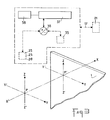
- the rectangular frame 3 is composed of four rigid bars which constitute its four sides, two frames 3a, 3b parallel to the axis YY ′ and two frames 3c and 3d parallel to the axis ZZ ′.
- FIG. 2 shows the arm 9 which moves along two guide rails 22 carried by the sides 3a and 3b of the frame 3.
- the movement is controlled for example by a servomotor 10 which drives a worm.
- a displacement sensor 23 of any known type, measures the displacements of the arm 9 and makes it possible to know, at all times, the exact position of the latter along the axis YY ′.
- the sensor 23 can be either a sensor for revolutions of the worm, or a sensor for linear magnetic or optical displacements.
- the carriage 11 can be moved along the arm 9, for example by a servomotor 12 driving a worm. It is guided by a guide rail 24.
- a sensor 25 measures the movements of the carriage and makes it possible to know its actual position along the axis ZZ ′.
- the carriage 11 carries guide rails 26 parallel to the axis XX ′ perpendicular to the plane of the figure, along which a tool holder 13 is moved by an actuator 27.
- a sensor 28 makes it possible to measure the displacements of the tool holder parallel to the axis XX ′ and to know the actual position along this axis.
- the three actuators 10, 12 and 27 make it possible to move the projection nozzles protected by the tool holder along three axes XX ′, YY ′ and ZZ ′ and the three sensors 23, 25 and 28 make it possible to know at all times the actual coordinates of the orifice of each nozzle with respect to a reference system composed of three trirectangular axes.
- the tool holder 13 can be pivotally mounted around two axes parallel to the axis ZZ ′ and to the axis YY ′, so that a system having five degrees of freedom is obtained, which makes it possible to maintain the projection nozzles perpendicular to the substrate, if the latter is curved.
- the device also includes sensors which measure the angles of rotation around the axes parallel to ZZ ′ and YY ′.
- Figure 2 shows a substrate 1 which is supported on a crossed frame 29, which is connected to the frame 3 and which has clamps 30 which enclose the substrate.
- the substrate can be fixed and, in this case, spacers are interposed between the frame 3 and the substrate.
- the frame 3 carries limit switches 31a, 31b which limit the stroke of the arm parallel to the axis YY ′, limit switches 32a, 32b, which limit the stroke of the carriage 11 parallel to the axis ZZ ′ And limit switches not visible in the figure which limit the travel of the tool holder parallel to the axis XX ′.
- the tool holder is connected to the central control station by electrical conductors 33 and by pneumatic lines 34.
- the frame 3 includes electrical connectors, pneumatic connectors and actuator connectors to which the conductors and connecting pipes are connected between the frame 3 and the central control station.
- Figure 2a is a perspective view on a larger scale on which we see the carriage 11 which slides along the arm 9 parallel to the axis ZZ ′.
- the carriage 11 carries a plate 86 which is rotated about an axis parallel to the axis YY ′ by a servomotor 87.
- a sensor 88 measures the actual rotation of the plate and sends the measurement signal to a comparator which is part a servo motor control loop 87.
- the turntable 86 carries a support 89 on which are mounted guide rods or slides or rails 26 parallel to the axis XX ′.
- the support 89 carries a servomotor 27 which rotates an endless screw 27a onto which is screwed a tool holder support 90 which slides on the slides 26.
- a sensor 28 measures the displacement of the tool holder support parallel to the axis XX ′, for example by measuring the number of turns of the screw 27a.
- the tool holder support 90 carries a servomotor 91 which rotates a shaft 92 parallel to the axis ZZ ′.
- a sensor 93 measures the angle of rotation.
- the shaft 92 carries a tool holder 13, in which are mounted tools 01, 02 ... On, which each comprise one or more nozzles for projecting a jet of colored liquid 94 which is parallel to the axis XX ′ And which comes to print a colored dot 95 on a substrate 1 placed opposite the tools.
- FIG. 3 schematically represents the position P of a tool, that is to say of the outlet orifice of one of the nozzles for spraying colored liquid.
- the point P ′ is the projection of the point P on the substrate 1 along the axis XX ′.
- FIG. 3 represents a diagram of the electronic circuits intended to control the coincidence between the points Q and P ′.
- This diagram shows the three position sensors 23, 25, 28 shown in FIG. 2.
- the reference 35 represents a memory of the central unit, in which are located at a given instant the set values which determine the theoretical coordinates of a point.
- Reference 36 represents comparators which compare the value measured by each sensor 23, 25 and 28 to its theoretical value. Each of these comparators is part of a local servo outlet of a servomotor 10, 12 or 27.
- the comparator 36 which may be part of the 'central unit, emits a signal and the central unit sends to the nozzle concerned a signal which controls the projection by this nozzle of a very fine droplet of liquid which produces on the substrate 1 a monochrome spot P ′ which coincides with the point theoretical Q.
- an electronic marking control device 37 for example a video camera, makes it possible to verify that the point P ′ is correctly positioned on the substrate.
- a print correction device 38 cancels the impact of the point P ′ by controlling the ejection on this point of an erasing liquid and we resume again the printing cycle of this same point P ′.
- FIG. 4 shows a schematic perspective view of a tool holder 13 carrying a plurality of tools 01, 02 ... On, the number n being any, for example equal to 12 in the case of the figure.
- the tool holder 13 includes a parallelepipedic case or case 13a in which the various tools 01, 02 ... 0n are mounted side by side, being aligned along several lines and columns parallel to the axes ZZ ′ and YY ′ respectively.
- Each tool comprises one or more nozzles for projecting liquid in a direction parallel to the axis XX ′.
- All the tools have the same general parallelepiped shape and the position of each tool is perfectly known as soon as we know the position of a reference linked to each tool, for example the position of the center C of the upper face.
- the coordinates of each tool are deduced by adding constants to the coordinates of a reference linked to the tool holder, for example from the center C ′ of the upper face of the housing 13a.
- the tools are assembled by joining each tool with the neighboring tools, for example by pins or tenons engaged in grooves or mortises.
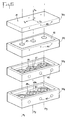
- FIG. 5 is a schematic perspective view of a tool O placed above a horizontal plane substrate 1.
- the tool O has a laminated structure, that is to say that it is composed of several superimposed rectangular plates 391, 392, 393, 394, in which liquid and compressed gas conduits and nozzles are hollowed out. projection of liquid which are parallel to the axis XX ′ and which open onto the underside of the lower plate 394.
- FIG. 5 represents an example, without any limiting character of a tool which comprises three nozzles whose axes P1, P2, P3 are offset both along the axis ZZ ′ and along the axis YY ′.
- the three nozzles can respectively project three colored liquids, different or identical, on the substrate 1 and a network of colored dots is shown thereon being executed, these dots being intended to represent a graphic.
- the coordinates of the frame C ′ linked to the tool holder make it possible to define the coordinates of the three nozzles.
- the tool holder is continuously moved parallel to the axis YY ′ and the liquid projections are controlled when each orifice passes in front of points P ′ distant from the value p which can vary within the same program .
- FIG. 5 shows limits L1, L2 parallel to the axis ZZ ′ and limits L3 and l4 parallel to the axis YY ′. These limits define the framework within which the graphics to be produced are located. These limits are determined by the data stored in memory with respect to the desired graphics and controlled by the sensors 23 for L1 and L2 and by the sensors 25 for L3 and L4.
- each nozzle passes successively opposite the theoretical points Q of the substrate and at this instant, one or more of the nozzles are 14 controlled by the central unit to project or not onto each point Q of the substrate, a stain of colored liquid.
- the central unit thus controls the simultaneous scanning of three lines by three nozzles until the tool guard reaches the limit L1.
- the central unit controls the movement of the carriage 11 parallel to the axis ZZ ′ by a value equal to z or a multiple of z and it again controls the movement of the tool holder parallel to the axis YY ′, in the opposite direction to the previous one until the tool holder reaches the limit L2.
- the central unit repeats these operations until the carriage 11, which has started from the limit L3, reaches the limit L4.
- each of the nozzles projects or not a colored liquid of determined color, independently and autonomously.
- Figure 6 is an exploded view and Figure 7 a section of the tool holder shown in Figure 5 passing through the axis P of a nozzle.
- the upper plate 391 acts as a cover. It includes the electrical components and circuits. It comprises in particular sockets 40 in which engage tensioning pins and sockets 41 for grounding.
- the plate 392 called the membrane support plate, comprises a membrane 42 against the upper face of which are placed piezoelectric plates 43, for example quartz plates or piezoelectric ceramics which are excited by voltage pulses. Each plate corresponds to one of the liquid injection nozzles.
- the deformations of the piezoelectric plates 43 are transmitted to the membrane 42 which acts as a piston which sucks and repels the colored liquid which generates a droplet of liquid during each pulse.
- the volume of the droplets depends on the amplitude of the pulses.
- the plate 392 comprises electrical connection sockets 44, in which are engaged pins for connecting the piezoelectric receiving plate 51 visible in FIG. 7.
- the plate 393 has the function of bringing colored liquids to each nozzle.
- This plate has a number of liquid inlet orifices 45 equal to the number of nozzles, for example three in the case of the figure.
- Each orifice 45 receives a liquid of determined color and communicates with a circular channel 46 which is hollowed out between the plates 392 and 393 and which brings the liquid by radial channels into an axial chamber 47 visible in FIG. 7, which shows that the chamber 47 is of revolution around the axis P of a nozzle and has the shape of a convergent nozzle, for example of nozzle with a frustoconical section or with parabolic walls.
- the plate 394 has the function of bringing into each nozzle a compressed gas which is used to project the colored liquid contained in the chamber 47 in the form of a nozzle.
- the plate 394 has channels 48 whose number corresponds to that of the nozzles. These channels are connected to a source of compressed gas.
- Each channel 48 communicates with a circular channel 48a, which is connected by radial channels to a second circular channel 48b coaxial with the first. It can be seen in FIG. 7 that each channel 48b communicates by inclined channels 49 with one of the nozzles 50 for spraying liquid.
- Figure 7 is a section of a tool O passing through the axis P of a nozzle, for example a cross section through a plane defined by the axes XX ′ and ZZ ′.
- the membrane 42 which is tightly sealed between the plate 391 and 392. It can be seen that the membrane 42 supports a first piezoelectric plate 43 glued to its upper face and a second piezoelectric plate 51 glued to its lower face. The two plates are fixed to the membrane 42 rigidly by a conductive resin or by any other equivalent means.
- the first plate 43 is excited by voltage pulses which are transmitted by pins 40a engaged in the sockets 40.
- the pins 40a are connected by conductors 52 shown in dotted lines to a connector 53.
- the second plate 51 captures the deformations of the membrane 42 and transforms them into voltage pulses which are transmitted to pins 44a engaged in the sockets 44.
- the sockets 44a are connected by a conductor 54 to the connector 53.
- the amplitude of the voltage pulses emitted by the wafer 51 measures the amplitude of the deformations of the membrane which conditions the volume of the droplets and therefore makes it possible to control the volume of the droplets.
- the membrane 42 constitutes the upper limit of the axial chamber 47 which is hollowed out inside the plates 392 393, 394 and which is delimited for example by parabolic walls of revolution around the axis P, which converge continuously towards the outlet nozzle 50.
- Seals 55 are interposed between the successive plates, along the edges thereof.
- the central parts of the plates 392, 393 and 394 are in direct contact, so that the circular channels 46, 48a, 48b and the radial channels are machined between the junctions of two successive plates, which facilitates machining.
- the channels 49 which serve to inject a compressed gas, open out near the outlet orifice of the nozzle 50 and are very inclined relative to the axis P.
- the channels 49 open into the nozzle slightly upstream of the meniscus 50a which limits the liquid when the piston 42 is in the liquid compression position, so that the gas jet carries with it the droplets.
- a colored liquid is brought into each chamber 47 by a liquid distributor 56 which is connected to the connector 53 by a pipe 57 and which is connected to one of the orifices 45 fitted to the plate 393.
- compressed gas is supplied to each pair of circular conduits 48a, 48b by an air distributor 58, which is connected to the connector 53 by a pneumatic line 59.
- Periodic cleaning of the axial chamber 47, of the channel 46, of the radial channels starting therefrom and of the inlet channel 45 is obtained by interrupting the arrival of colored liquid and by connecting the distributor 56, by a pipe 60, to the connector 53.
- the connector 53 which manages all the tasks performed by each nozzle is connected to an interface device 61 by a link bus 61a.
- the interface device 61 includes an air-electrical interface 63, for example solenoid valves which electrically control the arrival of compressed air on the various air distributor devices 58 equipping each nozzle with the same tool.
- an air-electrical interface 63 for example solenoid valves which electrically control the arrival of compressed air on the various air distributor devices 58 equipping each nozzle with the same tool.
- the interface device 61 also includes a colored-electric liquid interface 62, for example solenoid valves which electrically control the arrivals of colored liquids at the various distributors 56 equipping each nozzle with the same tool.
- a colored-electric liquid interface 62 for example solenoid valves which electrically control the arrivals of colored liquids at the various distributors 56 equipping each nozzle with the same tool.
- the interface device comprises an interface 64 which controls the excitation voltage sent to the pins 40a of the transmitter wafers 43. It also includes an interface 65a which controls the connections with the receiver wafers 51.
- the interface device finally comprises an interface 65 which makes it possible to electrically control the sending of a cleaning liquid on the pipes 60 after having interrupted the arrival of colored liquid.
- the interface device 61 is connected to the central unit by a bus 66, by which the central unit sends to the interface devices 61 the logic command and control signals.
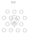
- FIG. 8 is a partial view on a large scale of the colored dots projected on a flat substrate.
- the points are circular and have diameters ⁇ equal or not.
- the points of the same diameter are equidistant on each line parallel to YY ′, the distance between points being equal to e.
- the spacing between the successive lines and the lateral offset of the points are such that the points are arranged at the vertices of equilateral triangles whose sides are equal to ⁇ + e. This arrangement makes it possible to obtain a maximum density of points per unit of area and contributes to obtaining high-resolution graphics.
- FIG. 9 schematically represents the general organization of the components and circuits of the central control station shown in FIG. 1.
- the reference 67 represents a central processor which controls all of the operations by dialoguing with other components via a central bus 68.
- the microprocessor 67 is connected to the central bus by a link bus 69.
- the central bus comprises for example three specialized buses, namely an addressing bus 70, a data bus 71 and a control bus 72.
- the reference 73 represents mass memories which include for example a RAM read and write memory 73a and a read ROM read memory 73b.
- the memories 73a and 73b are connected to the central bus by link buses 74a and 74b.
- the reference 75 represents a control console which is connected to the central bus by a link bus 76.
- the reference numeral 18 designates the module for creating and analyzing digital images shown in FIG. 1. This comprises random access memories RAM and read-only memories ROM and it is connected to the central bus by a link bus 77.
- the reference 78 represents a device for controlling the movements of the arm 9, of the carriage 11 and of the tool holder 13. It is connected to the central bus by a connection bus 79.
- the reference 80 represents an interface control device 61 which is connected to the central bus by the link bus 66.
- the reference 82 represents a device for processing colored liquids which is connected to the central bus by a connection bus 83.
- the reference 84 represents a control module for different devices which can optionally be fitted to a machine according to the invention, for example the device 37 which controls the marking.
- This module is connected to the central bus by a link bus 85.
Landscapes
- Coating Apparatus (AREA)
- Spray Control Apparatus (AREA)
Applications Claiming Priority (2)
| Application Number | Priority Date | Filing Date | Title |
|---|---|---|---|
| FR8803767 | 1988-03-18 | ||
| FR8803767A FR2628658B1 (fr) | 1988-03-18 | 1988-03-18 | Procedes et dispositifs automatiques pour inscrire des graphismes a haute resolution sur un subjectile par projection de gouttelettes de liquides colores |
Publications (1)
| Publication Number | Publication Date |
|---|---|
| EP0333609A1 true EP0333609A1 (de) | 1989-09-20 |
Family
ID=9364545
Family Applications (1)
| Application Number | Title | Priority Date | Filing Date |
|---|---|---|---|
| EP89430004A Withdrawn EP0333609A1 (de) | 1988-03-18 | 1989-03-16 | Automatische Verfahren und Vorrichtungen zum Schreiben hochaufgelöster Schriftzeichen auf ein Objekt durch Ausstoss farbiger Flüssigkeitströpfchen |
Country Status (3)
| Country | Link |
|---|---|
| US (1) | US4920422A (de) |
| EP (1) | EP0333609A1 (de) |
| FR (1) | FR2628658B1 (de) |
Cited By (11)
| Publication number | Priority date | Publication date | Assignee | Title |
|---|---|---|---|---|
| FR2735420A1 (fr) * | 1995-06-14 | 1996-12-20 | Gaujal Jean Louis | Imprimante d'ordinateur pour impression verticale |
| EP0761438A2 (de) * | 1995-09-05 | 1997-03-12 | Tampoprint GmbH | Bemusterungsvorrichtung |
| EP0970811A1 (de) * | 1998-07-06 | 2000-01-12 | L.A.C. Corporation | Automatische Beschichtungsvorrichtung |
| US6056454A (en) * | 1998-10-05 | 2000-05-02 | Gerber Technology, Inc. | Method and apparatus for printing on a continuously moving sheet of work material |
| EP0990522A3 (de) * | 1998-09-30 | 2000-10-18 | Stefano Germena | Verfahren, Vorrichtung und System zum Bedrucken von dreidimensionalen Gegenständen |
| EP1065055A1 (de) * | 1999-07-01 | 2001-01-03 | SARL A I M Société à responsabilité limitée | Vorrichtung zum Dekorieren von voluminösen Gegenständen |
| EP2357090A3 (de) * | 2009-12-16 | 2012-10-31 | Ulrich Kottke | Verfahren und Vorrichtung zur grafischen Gestaltung von Flächen |
| CN104044352A (zh) * | 2014-06-18 | 2014-09-17 | 浙江工业大学 | 一种基于图像分割的自动着色方法与着色装置 |
| CN109794377A (zh) * | 2018-12-29 | 2019-05-24 | 广州大学 | 一种适用于回转体上色物自动涂色的装置及方法 |
| CN111372690A (zh) * | 2017-09-27 | 2020-07-03 | 杜尔系统股份公司 | 包括集成控制电路的施涂器 |
| US11084301B2 (en) * | 2016-02-05 | 2021-08-10 | A. Schmidt e.K. | Printing method and printing device |
Families Citing this family (26)
| Publication number | Priority date | Publication date | Assignee | Title |
|---|---|---|---|---|
| US5184336A (en) * | 1989-01-18 | 1993-02-02 | Hewlett-Packard Company | Mechanical assembly for alternately producing displacement of a carriage and rotation of a carriage mounted gear |
| US4991116A (en) * | 1990-01-03 | 1991-02-05 | Jack Hohner | Combined digitizer and plotter for computer aided drawing |
| US5740051A (en) * | 1991-01-25 | 1998-04-14 | Sanders Prototypes, Inc. | 3-D model making |
| US5506607A (en) * | 1991-01-25 | 1996-04-09 | Sanders Prototypes Inc. | 3-D model maker |
| GB2291838B (en) * | 1994-07-29 | 1998-11-18 | Robert John Young | A machine and method for printing on an edible substrate |
| US6536345B1 (en) | 1994-07-29 | 2003-03-25 | Cadex Limited | Printing on the surface of edible substrates |
| GB9507140D0 (en) * | 1995-04-06 | 1995-05-31 | Icg Ltd | Platesetter |
| US5984470A (en) * | 1995-04-20 | 1999-11-16 | Canon Kabushiki Kaisha | Apparatus for producing color filter with alignment error detection |
| DE19634582C2 (de) * | 1996-08-27 | 1998-07-09 | Polytronic Grosbildkommunikati | Computergesteuertes mobiles Großfarbgebungssystem |
| US6554991B1 (en) * | 1997-06-24 | 2003-04-29 | Large Scale Proteomics Corporation | Automated system for two-dimensional electrophoresis |
| DE19852079A1 (de) * | 1998-11-11 | 2000-05-18 | Thomas Kovarovsky | Bildgebende Lackiervorrichtung |
| JP3868674B2 (ja) * | 1999-08-09 | 2007-01-17 | 株式会社小糸製作所 | 光源バルブの製造方法 |
| DE10202553A1 (de) * | 2002-01-24 | 2003-08-07 | Burkhard Buestgens | Verfahren zum Auftragen von Farben oder Lacken |
| US6832864B2 (en) * | 2003-01-16 | 2004-12-21 | Eastman Kodak Company | Printing apparatus for printing an image on a selected surface |
| US20050003056A1 (en) * | 2003-07-02 | 2005-01-06 | The Procter & Gamble Company | Article of commerce comprising edible substrate, image, and message |
| US7593563B2 (en) * | 2003-07-11 | 2009-09-22 | The Procter & Gamble Company | Image variety on edible substrates |
| US20050058749A1 (en) * | 2003-09-17 | 2005-03-17 | The Procter & Gamble Company | Image exposure control in edible substrates |
| US20050058753A1 (en) * | 2003-09-17 | 2005-03-17 | The Procter & Gamble Company | Method to increase image variety with limited image components |
| US7350890B2 (en) * | 2004-08-26 | 2008-04-01 | The Boeing Company | Apparatus and methods for applying images to a surface |
| DE102005003333A1 (de) * | 2005-01-25 | 2006-07-27 | Büstgens, Burkhard, Dr.-Ing. | Verfahren für den positionsabhängigen Farbauftrag auf konturierten Flächen |
| US20060228143A1 (en) * | 2005-04-06 | 2006-10-12 | Hsiu Chi Kuo | Portable printer enabling to directly print on an object surface |
| ITUD20110072A1 (it) * | 2011-05-13 | 2012-11-14 | Giacomo Battiston | Dispositivo per la riproduzione di immagini o motivi grafici in genere su superfici, e relativo procedimento |
| CN103223388B (zh) * | 2013-04-02 | 2015-06-03 | 南京化工职业技术学院 | 金属圆盘自动喷漆装置及其喷漆方法 |
| CN205651845U (zh) * | 2013-04-08 | 2016-10-19 | 卡洛·菲利波·拉蒂 | 竖直绘图器 |
| JP6487165B2 (ja) * | 2014-08-27 | 2019-03-20 | ファナック株式会社 | 工具情報読み書き装置を備えた工作機械 |
| CN110370813B (zh) * | 2019-08-06 | 2021-04-13 | 天石(深圳)技研有限公司 | 一种打标装置 |
Citations (4)
| Publication number | Priority date | Publication date | Assignee | Title |
|---|---|---|---|---|
| AU430929B2 (en) * | 1971-06-17 | 1972-12-08 | Nippon Enlarging Color Inc. | A method for enlarged multicolor printing anda device therefor |
| US4358781A (en) * | 1979-11-07 | 1982-11-09 | Matsushita Electric Industrial Company, Limited | Ink jet writing head with spacer in capillary chamber |
| US4580914A (en) * | 1984-08-02 | 1986-04-08 | Metromedia, Inc. | Apparatus and method for positioning an ink-jet printing head |
| FR2601265A1 (fr) * | 1986-05-28 | 1988-01-15 | Cherubin Grillo Victor | Systeme pictural d'impression polychrome point par point sur une surface plane ou en relief, commande par micro-processeur. |
Family Cites Families (2)
| Publication number | Priority date | Publication date | Assignee | Title |
|---|---|---|---|---|
| US3867882A (en) * | 1973-04-19 | 1975-02-25 | Houston Eng Res | Apparatus for printing labels directly onto packages, containers and the like |
| US4547786A (en) * | 1984-08-02 | 1985-10-15 | Metromedia, Inc. | Ink jet printing system |
-
1988
- 1988-03-18 FR FR8803767A patent/FR2628658B1/fr not_active Expired - Lifetime
-
1989
- 1989-03-16 EP EP89430004A patent/EP0333609A1/de not_active Withdrawn
- 1989-03-16 US US07/324,607 patent/US4920422A/en not_active Expired - Fee Related
Patent Citations (4)
| Publication number | Priority date | Publication date | Assignee | Title |
|---|---|---|---|---|
| AU430929B2 (en) * | 1971-06-17 | 1972-12-08 | Nippon Enlarging Color Inc. | A method for enlarged multicolor printing anda device therefor |
| US4358781A (en) * | 1979-11-07 | 1982-11-09 | Matsushita Electric Industrial Company, Limited | Ink jet writing head with spacer in capillary chamber |
| US4580914A (en) * | 1984-08-02 | 1986-04-08 | Metromedia, Inc. | Apparatus and method for positioning an ink-jet printing head |
| FR2601265A1 (fr) * | 1986-05-28 | 1988-01-15 | Cherubin Grillo Victor | Systeme pictural d'impression polychrome point par point sur une surface plane ou en relief, commande par micro-processeur. |
Non-Patent Citations (1)
| Title |
|---|
| PATENT ABSTRACTS OF JAPAN, vol. 10, no. 40 (M-454)[2097], 18th February 1986; & JP-A-60 193 657 (TOOA EREKUTORON K.K.) 02-10-1985 * |
Cited By (18)
| Publication number | Priority date | Publication date | Assignee | Title |
|---|---|---|---|---|
| FR2735420A1 (fr) * | 1995-06-14 | 1996-12-20 | Gaujal Jean Louis | Imprimante d'ordinateur pour impression verticale |
| EP0761438A2 (de) * | 1995-09-05 | 1997-03-12 | Tampoprint GmbH | Bemusterungsvorrichtung |
| EP0761438A3 (de) * | 1995-09-05 | 1997-11-05 | Tampoprint GmbH | Bemusterungsvorrichtung |
| EP0970811A1 (de) * | 1998-07-06 | 2000-01-12 | L.A.C. Corporation | Automatische Beschichtungsvorrichtung |
| US6096132A (en) * | 1998-07-06 | 2000-08-01 | L.A.C. Corporation | Automatic painting device |
| EP0990522A3 (de) * | 1998-09-30 | 2000-10-18 | Stefano Germena | Verfahren, Vorrichtung und System zum Bedrucken von dreidimensionalen Gegenständen |
| US6431773B1 (en) | 1998-10-05 | 2002-08-13 | Gerber Technology, Inc. | Method and apparatus for printing on a continuously moving sheet of work material |
| US6056454A (en) * | 1998-10-05 | 2000-05-02 | Gerber Technology, Inc. | Method and apparatus for printing on a continuously moving sheet of work material |
| US6076983A (en) * | 1998-10-05 | 2000-06-20 | Gerber Technology, Inc. | Method and apparatus for printing onto a continuously advancing web of work material |
| EP1065055A1 (de) * | 1999-07-01 | 2001-01-03 | SARL A I M Société à responsabilité limitée | Vorrichtung zum Dekorieren von voluminösen Gegenständen |
| FR2795662A1 (fr) * | 1999-07-01 | 2001-01-05 | Sarl A I M | Dispositif muni d'une tete d'impression permettant de realiser des decorations sur des objets volumineux |
| EP2357090A3 (de) * | 2009-12-16 | 2012-10-31 | Ulrich Kottke | Verfahren und Vorrichtung zur grafischen Gestaltung von Flächen |
| CN104044352A (zh) * | 2014-06-18 | 2014-09-17 | 浙江工业大学 | 一种基于图像分割的自动着色方法与着色装置 |
| CN104044352B (zh) * | 2014-06-18 | 2016-05-18 | 浙江工业大学 | 一种基于图像分割的自动着色方法与着色装置 |
| US11084301B2 (en) * | 2016-02-05 | 2021-08-10 | A. Schmidt e.K. | Printing method and printing device |
| CN111372690A (zh) * | 2017-09-27 | 2020-07-03 | 杜尔系统股份公司 | 包括集成控制电路的施涂器 |
| CN111372690B (zh) * | 2017-09-27 | 2021-09-14 | 杜尔系统股份公司 | 包括集成控制电路的施涂器 |
| CN109794377A (zh) * | 2018-12-29 | 2019-05-24 | 广州大学 | 一种适用于回转体上色物自动涂色的装置及方法 |
Also Published As
| Publication number | Publication date |
|---|---|
| FR2628658A1 (fr) | 1989-09-22 |
| US4920422A (en) | 1990-04-24 |
| FR2628658B1 (fr) | 1990-08-10 |
Similar Documents
| Publication | Publication Date | Title |
|---|---|---|
| EP0333609A1 (de) | Automatische Verfahren und Vorrichtungen zum Schreiben hochaufgelöster Schriftzeichen auf ein Objekt durch Ausstoss farbiger Flüssigkeitströpfchen | |
| JP5073501B2 (ja) | プラスチック容器上にデジタル画像を印刷する方法 | |
| US10279600B2 (en) | Direct printing machine and method for printing containers using direct printing | |
| CN100408457C (zh) | 与成卷制品有关的编码应用设备 | |
| US6578276B2 (en) | Apparatus and method for marking multiple colors on a contoured surface having a complex topography | |
| US20010017085A1 (en) | Apparatus for and method of printing on three-dimensional object | |
| JP2005053227A (ja) | 保守方法およびドラムプリンタ | |
| TW200920606A (en) | Print head unit and method for manufacturing patterned layer on substrate with the same | |
| US20230391105A1 (en) | Ejection control using imager | |
| JP5958720B2 (ja) | 画像または一般にグラフィカルパターンを表面上に再現するためのデバイスおよび対応する方法 | |
| JP2003175594A (ja) | プリントシステムにおける組織学的試料のためのカセット及び/又は試料支持体のプリント装置 | |
| JP2003118173A (ja) | インクジェットによる光ディスクへの画像形成方法 | |
| JPH0575588B2 (de) | ||
| JP2020189444A (ja) | 印刷装置 | |
| EP0241118B1 (de) | Gerät zur Reproduktion von Dokumenten | |
| KR100312924B1 (ko) | 제조품의 스캔 마킹 | |
| US10005303B2 (en) | System for detecting inoperative inkjets in three-dimensional object printing using a profilometer and predetermined test pattern printing | |
| JP2008213319A (ja) | 印刷装置および印刷方法 | |
| JPH09123482A (ja) | ライン型カラー記録装置における記録位置補正方法およびライン型カラー記録装置 | |
| CN101353090A (zh) | 与成卷制品有关的装置 | |
| JP2012035552A (ja) | 立体物への印刷方法 | |
| CN2663151Y (zh) | 金属铭牌自动打印机 | |
| JPH0247076A (ja) | 記録装置 | |
| JP2006027225A (ja) | インクジェット記録装置 | |
| FR2475722A3 (fr) | Appareil enregistreur a dispositif d'ecriture |
Legal Events
| Date | Code | Title | Description |
|---|---|---|---|
| PUAI | Public reference made under article 153(3) epc to a published international application that has entered the european phase |
Free format text: ORIGINAL CODE: 0009012 |
|
| AK | Designated contracting states |
Kind code of ref document: A1 Designated state(s): AT BE CH DE ES GB IT LI NL SE |
|
| 17P | Request for examination filed |
Effective date: 19891229 |
|
| 17Q | First examination report despatched |
Effective date: 19910621 |
|
| STAA | Information on the status of an ep patent application or granted ep patent |
Free format text: STATUS: THE APPLICATION IS DEEMED TO BE WITHDRAWN |
|
| 18D | Application deemed to be withdrawn |
Effective date: 19911105 |