EP0332894B1 - Schlagstock mit rechtwinklig angebrachtem Griff - Google Patents
Schlagstock mit rechtwinklig angebrachtem Griff Download PDFInfo
- Publication number
- EP0332894B1 EP0332894B1 EP89103106A EP89103106A EP0332894B1 EP 0332894 B1 EP0332894 B1 EP 0332894B1 EP 89103106 A EP89103106 A EP 89103106A EP 89103106 A EP89103106 A EP 89103106A EP 0332894 B1 EP0332894 B1 EP 0332894B1
- Authority
- EP
- European Patent Office
- Prior art keywords
- club
- crosshandle
- rod
- noted
- shaft
- Prior art date
- Legal status (The legal status is an assumption and is not a legal conclusion. Google has not performed a legal analysis and makes no representation as to the accuracy of the status listed.)
- Expired
Links
- 239000011796 hollow space material Substances 0.000 claims description 7
- 230000033001 locomotion Effects 0.000 claims description 5
- 239000000463 material Substances 0.000 claims description 4
- 238000006073 displacement reaction Methods 0.000 claims description 2
- 238000007493 shaping process Methods 0.000 claims 1
- 239000007789 gas Substances 0.000 description 10
- 235000005156 Brassica carinata Nutrition 0.000 description 3
- 244000257790 Brassica carinata Species 0.000 description 3
- 239000002184 metal Substances 0.000 description 2
- 239000004033 plastic Substances 0.000 description 2
- 239000006096 absorbing agent Substances 0.000 description 1
- 239000004760 aramid Substances 0.000 description 1
- 229920006231 aramid fiber Polymers 0.000 description 1
- 239000011324 bead Substances 0.000 description 1
- 230000000903 blocking effect Effects 0.000 description 1
- 238000005266 casting Methods 0.000 description 1
- 239000012141 concentrate Substances 0.000 description 1
- 230000001419 dependent effect Effects 0.000 description 1
- 239000000835 fiber Substances 0.000 description 1
- -1 for instance Substances 0.000 description 1
- 239000002923 metal particle Substances 0.000 description 1
- 239000002245 particle Substances 0.000 description 1
- IMACFCSSMIZSPP-UHFFFAOYSA-N phenacyl chloride Chemical compound ClCC(=O)C1=CC=CC=C1 IMACFCSSMIZSPP-UHFFFAOYSA-N 0.000 description 1
- 230000035939 shock Effects 0.000 description 1
- 239000003491 tear gas Substances 0.000 description 1
Images


Classifications
-
- F—MECHANICAL ENGINEERING; LIGHTING; HEATING; WEAPONS; BLASTING
- F41—WEAPONS
- F41B—WEAPONS FOR PROJECTING MISSILES WITHOUT USE OF EXPLOSIVE OR COMBUSTIBLE PROPELLANT CHARGE; WEAPONS NOT OTHERWISE PROVIDED FOR
- F41B15/00—Weapons not otherwise provided for, e.g. nunchakus, throwing knives
- F41B15/02—Batons; Truncheons; Sticks; Shillelaghs
-
- F—MECHANICAL ENGINEERING; LIGHTING; HEATING; WEAPONS; BLASTING
- F21—LIGHTING
- F21V—FUNCTIONAL FEATURES OR DETAILS OF LIGHTING DEVICES OR SYSTEMS THEREOF; STRUCTURAL COMBINATIONS OF LIGHTING DEVICES WITH OTHER ARTICLES, NOT OTHERWISE PROVIDED FOR
- F21V33/00—Structural combinations of lighting devices with other articles, not otherwise provided for
- F21V33/0064—Health, life-saving or fire-fighting equipment
Definitions
- This invention relates to a guard baton or police billy or the like, and in particular to a crosshandled guard baton.
- crosshandled guard baton means a guard baton which has a short handle branchedly secured on a main club body at midway between an end and the central portion of the club length.
- a conventional guard baton of this type is described in US Patent 4132409.
- the guard baton comprises a club having a crosshandle rigidly secured thereto and extending perpendicularly therefrom.
- An outer part of the handle defines a gripping surface which is stationary with respect to the club.
- a sleeve is rotatably mounted on the handle between the club and the gripping surface.
- the handle is axially divided into a stationary portion and a rotatable portion, the former being gripped by several fingers of the user's hand to brake rotating or swinging motions of the club.
- the braking means provided are such that it is difficult to stop quickly the rotation of the club when necessary. Also, braking the rotation of the club only with the fingers of a hand may be harmful to the user.
- KARATE is a special practice for combat according to which wielding of two hands is important, and also quick blocking of a hand action is necessary to make use of a foot for kicking or to add an attack by footwork.
- the present invention provides a rotatable crosshandled guard baton with improved braking means in order to enable KARATE actions in enlarged scale for the user against any assailant.
- the crosshandled guard baton of the present invention comprises a club and a crosshandle transversely branched on the club.
- Said crosshandle comprises a main portion and a mounting base slidably contacting each other, the mounting base being fixed on the club, said crosshandle having internally a shaft an end of which is secured to the club through the mounting base, the main portion of the crosshandle being rotatably supported by said shaft.
- Said guard baton comprises braking means for controlling the rotation between the crosshandle and the club, a manual control rod or the like substantially parallel to said shaft in the crosshandle, and spring means associated to the manual control rod or the like, so as to allow or brake the rotation of the club around the crosshandle by manual action of the rod.
- the crosshandled guard baton comprises a club and a crosshandle transversely branched on the club.
- Said crosshandle comprises a main portion and a mounting base slidably contacting each other, the mounting base being fixed on the club, said crosshandle having internally a shaft an end of which is secured to the club through the mounting base, the main portion of the crosshandle being rotatably supported by said shaft.
- Said crosshandle comprises a stopper pin parallel to said shaft across the plane formed by the slidable contact between the mounting base and the main portion of the crosshandle, said stopper pin being secured at its club end and removably fitted at its crosshandle end in a recess formed in the main portion, a coil spring being provided around the shaft at its end far from the club enabling the displacement of the main portion along the shaft, so as to allow or brake manually the rotation of the club around the crosshandle, by virtue of the disengagement or engagement of the stopper pin in the recess in the main portion.
- Fig. 1 shows a perspective view of an inventive embodiment wherein a longitudinal length of the club and the same of the handle is not proportional to the scale.
- Fig. 2 shows a vertically sectioned view of the embodiment as shown in Fig. 1.
- Fig. 3 shows a vertically sectioned view of another inventive embodiment.
- Fig. 4 shows a perspective view of a still another inventive embodiment.
- Fig. 5 shows a vertically sectioned view of the embodiment as shown in Fig. 4.
- Fig. 6 shows a vertically sectioned view of a still another further inventive embodiment.
- Fig. 7 shows a side view, mainly broken, to indicate internal structures.
- Figs. 8 to 14 show vertically sectioned views to respectively indicate varient devices mounted on inventive embodiments.
- Fig. 15 shows a side view, partly broken, to indicate varient internal devices.
- Figs. 16 and 17 show vertically sectioned views to respectively indicate varient devices mounted on inventive embodiments.
- the numeral 1 indicates a club having a longitudianl axis and 2 indicates a crosshandle which is branchedly mounted at a place toward an end of the club and has a longitudinal axis transversal to the club axis.
- the handle is provided with an elliptical shape in section.
- the major axis of the elliptical section of the handle 2 is substantially conformed to the club axis, and the handle is also provided preferably with a length comparable to a breadthal length of a man's palm.
- 4 is a plane to form a slide contact made of metal or an interspace between main portion of the handle to be out of club motion and a mounting base 61 of the handle to be integral with the club motion as will be apparent by description later.
- FIG. 2 5 is a rod which is inserted through a hole provided in parallel to the handle axis and at its far end. The rod is blocked and is leveled to be just over the handle end so that a user may manipulate the rod end as a key or trigger and at outer portion 6 the rod is wound around with a coil spring 7 set on a stepped corner of the hole to yield a urging action .
- the shaft 3 is a shaft which is provided internally of the handle 2 and is substantially parallel to the rod 5.
- the shaft is received in a hole and is rotatably supported with ball bearings 11, 11 which are provided at an outer point and at the plane 4, but at its close end, the shaft 3 is secured in the club 1 so that the shaft will rotate integrally with the club, but the main portion of the handle which designates portion of the handle outer or farther than the plane 4 will stay out of such a rotation by dint of the rotatable supports 11, 11.
- a shaft 3 is designed to act as a rotating shaft as well as a rod to release resistance to rotation which is assigned to a pin 12.
- the pin 12 is secured in the club through the mounting base 61 and is extended across the plane 4 slightly in a recess provided with the main portion of the handle. Therefore, when the handle 2 is pulled or displaced outwardly relative to the shaft 3 to make an interspace to be clear of an end of the pin 12, the club is allowed to turn and a release of pull force acting on the handle will brake, wherein a spring 7 will reset the shaft 3.
- a ring strap band 14 is provided to make sure a gripping by the hand which is tied with a mounting end 13 the location of which may be chosen at any place around the handle. Further, interior of the club is rendered to be a hollow space 15 to make the baton lighter in weight and two end openings 16 are closed by plugs 17.
- this embodiment is comparable to the embodiment as shown in Figs 1 and 2 in respect to designs with a shaft 3 and a rod 5 and with attendant devices.
- a trigger 18 is provided at a side face of the handle far end and is internally extended to form a lever to contact with the top or outmost end of the rod 5 so that a push of the trigger 18 will cause the rod 5 to a move inward.
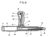
- the interior of the club 1 is divided into two longitudinal spaces 15, 33 and each of opening 16 is closed by a plug 17.
- the rod 5 has a blocked head at its inner end and a coil spring 7 is set to wind around midportion of the rod 5 to urge the blocked head to be across the plane 4 and normally to be received in a recess 19 provided in the club 1, and a trigger 18 is formed to be a lever to engage with outermost end of the rod 5 such that a push of the trigger 18 will cause a move outwardly of the rod 5.
- a trigger 18 is engaged to a roll 20 which is mounted at or formed on the outmost end of the rod 5, the rod 5 having a hole 21 adjacent to the roll 20 for receiving therethrough threaded the pivotable lever end of the trigger 18.
- An internal core portion 22 of the club 1 is made of a hard material, for instance, hard plastic, and wrapped or claded with an elastic, for instance, spongy material 23 to avoid a slip.
- a shaft 3 is set up to be sheathed with a tube and at its close end, the shaft 3 is not extended in the club 1 and is secured in the mounting base 61.
- Another base member 30 is fixded integrally on the mounting base to further secure the shaft 3 .
- One side face of the base member 30 is made flush vertically with a cover of the ball bearing 11 for the shaft, said cover corresponding to close end of the tube sheathing the shaft 3.
- a rod is formed to be a slightly flexed lever 28 extending vertically in parallel to the shaft 3, and outmost end of the lever 28 is formed to be a trigger 18 to face out at a side of far end of the handle 2 and the trigger 18 is urged with a spring 32 which is set transversal to the sheath tube, and at a midpoint 29 the lever is pivoted, and at its close end or inner end, the lever 28 is blocked so as to press on both said ball bearing cover and said base member 30 with a slight gap inbetween such that normally, by pressing, the club 1 integral with the base member 30 is not allowed to turn, but a push of the trigger 18 will cause a release of the pressing, which will allow rotation around the shaft 32 wherein the base member 30 is involved in rotation.
- the club 1 has an extending interior hollow space 15, an opening of one end adjacent to the handle is plugged by a plug 17, and another far end opening is made open to communicate outside.
- a plurality of slender cylinderical members in retracted form and extendable telescopically are provided, wherein a member 25 having a larger diameter than the other members is shaped to be thick at its end placed to be close to the plug 17 and thin at its end placed to be a slightly out of the open end of the club 1 to form a subtle taper forward as a whole, wherein an inner member 27 is so inserted as for its outer end to be fitted tightly with the end of the member 25, the outer opening end of the member 27 being plugged with a cap 26.
- These retracted members 25, 27 will be extended with help of centrifugal force when the club is gripped at the club grip 24 by a user and put into a swing motion, for instance.
- an outer member 25 is designed to be an outwardly tapered cylinder having an end wall 59 which is internally fixed midway of the club length and thereinto an inner member 27 is inserted, but it contains, with help of the plug 26, metal beads or particles 34 to make a weight, which will accelerate the centrifugal force, wherein for the purpose of avoiding easy or unexpected extension of the members due to a small centrifugal force, fittings between the club end, the member 25 and the member 27 are made adequately tight.
- both figures 8 + 9,24 indicates a grip portion on the club as well as a cover placed on the portion to avoid slipping of the hand.
- Fig. 11 Additional feature in Fig. 11 is equipment of a gas ejecting device contained in the club body 1, wherein 38 is a gas bomb and 40 is a nob switch or trigger to burst the bomb and 41 is a gas ejecting nozzle, through which an exploded gas, for instance, tear gas or smoky gas will be ejected outside.
- 38 is a gas bomb and 40 is a nob switch or trigger to burst the bomb and 41 is a gas ejecting nozzle, through which an exploded gas, for instance, tear gas or smoky gas will be ejected outside.
- a shaft 3 is set at a center and a rod lever 28 is pivotally mounted generally in parallel to the shaft 3 at a off-center position and is formed at its far end to be a trigger 18 which is urged with a spring 36 set transversely and at its close end the lever 28 is designed to press on both a bearing cover and a base member which is formed on a mounting base 61 as in much the same manner as described in Fig. 8.
- a gas bomb 38 is set such that a switch 40 located adjacent to the mounting base 61 will act, via a contact with a fuse 60, on the bomb 38 and in another space, a plurality of extendable members in a retracted form is accommodated in much the same manner as described in Fig. 9.
- this embodiment is compared to that in Fig. 1 in respect to arrangement of a shaft 3 and a rod 5.
- a device is directed to connection of a trigger 18 to an end of the rod 5, wherein a blocked end 45 is beveled to form an inclined face 37, close to which a ram 46 is set to transmit an action of the trigger 18 to the inclined face 37.
- set is a lightening device wherein 47 is a battery, 48 is a lamp and 50 is a lens winder as is easily understood and another space accommodates much the same device as described in the foregoing example.
- a device for a trigger 18 is formed of a ram and piston to stroke in a cylinder, located to be adjacent to a beveled face 37 of a blocked head 45 of a shaft 5 in much the same manner in the foregoing example.
- a lightening device with much the same design as in the foregoing example is accommodated in the space 15 and another space is kept hollow.
- a trigger 18 is formed to be a ram having a beveled undercut to keep contact with a far end of a shaft 5.
- a cap 58 is fitted over to avoid slipping for the hand, wherein the cap is preferably made of a spongy material.
- the club 1 is made of a plastic, it is recommended to reinforce with making an interlacing layer 44 made of tough aramid fibers, for instance, Keblar (brandname) by orienting such fibers to the longitudinal axis of the club.
- a trigger 18 is set to swing by a push, underside of which a lever 51 shaped in a L letter pattern in section is suspended, and its lateral portion is set to be in contact on an end of a rod 5 such that a push of the trigger 18 will cause the rod 5 to move inwardly in much the same manner as described before.
- a lightening device and a gas ejecting device are accommodated, but a direction of casting light and that of ejecting gas are conformed as is shown to left in the drawing, wherein the device for ejecting a gas is set in the right-half space 33 and a nozzle 39 is directed to left therein.
- a trigger 18 is extended inwardly to have a hole 53 and therethrough a blocked far end 52 of a rod 5 is threaded to make an engagement.
- a pointing device is mounted so as to facilitate a jab action wherein a plug 17 is provided with a through hole 54 and therethrough a pointer member 55 is fitted and an assembly of the pointer 55 and the plug 17 is set so as to connect to a pack 56 mounted inwardly wherein a tip of the pointer 55 is adjusted to be slightly out of the rod end, and 57 is a shock absorber.
Landscapes
- Engineering & Computer Science (AREA)
- General Engineering & Computer Science (AREA)
- Golf Clubs (AREA)
- Details Of Spanners, Wrenches, And Screw Drivers And Accessories (AREA)
- Finger-Pressure Massage (AREA)
Claims (17)
- Querhandgriff-Schlagstock mit einem Stock (1) und einem Querhandgriff (2), der auf dem Stock quer abgezweigt ist, wobei der Querhandgriff aufweist: einen Hauptabschnitt, eine Befestigungsbasis (61) und einen inneren Schaft (3), dessen eines Ende über die Befestigungsbasis an dem Stock befestigt ist, wobei die Befestigungsbasis an dem Stock befestigt ist, dadurch gekennzeichnet, daß
der Hauptabschnitt des Querhandgriffes durch den Schaft drehbar getragen wird und in gleitendem Kontakt mit der Befestigungsbasis ist, und
der Schlagstock aufweist: eine Bremseinrichtung (9, 10; 5, 7; 30; 31) zum Steuern der Drehung zwischen dem Querhandgriff und dem Stock, einen manuellen Steuerstab oder ähnliches (5, 28), im wesentlichen parallel zu dem Schaft in dem Querhandgriff, und eine Federeinrichtung (7; 32, 36), die dem manuellen Steuerstab oder ähnlichem zugeordnet ist, um so die Drehung des Stockes (1) um den Querhandgriff durch manuelle Betätigung des Stabes oder ähnlichem zu gestatten oder zu bremsen. - Querhandgriff-Schlagstock mit einem Stock (1) und einem Querhandgriff (2), der auf dem Stock quer abgezweigt ist, wobei der Querhandgriff aufweist: einen Hauptabschnitt, eine Befestigungsbasis (61) und einen inneren Schaft (3), dessen eines Ende über die Befestigungsbasis an dem Stock befestigt ist, wobei die Befestigungsbasis an dem Stock befestigt ist, dadurch gekennzeichnet, daß
der Hauptabschnitt des Querhandgriffes durch den Schaft drehbar getragen wird und in gleitendem Kontakt mit der Befestigungsbasis ist, und
der Querhandgriff (2) aufweist: einen Stopper-Stift (12), parallel zu dem Schaft und durch die Ebene (4), die von dem gleitenden Kontakt zwischen der Befestigungsbasis (61) und dem Hauptabschnitt des Querhandgriffes gebildet wird, wobei der Stopper-Stift an seinem Stockende befestigt ist und an seinem Querhandgriffende entfernbar in einer Aussparung eingepaßt ist, die in dem Hauptabschnitt ausgebildet ist, und eine Spiralfeder (7), die um den Schaft (3) herum an seinem von dem Stock entfernten Ende vorgesehen ist, um die Verschiebung des Hauptabschnittes längs des Schaftes zu ermöglichen und so manuell die Drehung des Stockes um den Querhandgriff, infolge des Nichteingriffs oder Eingriffs des Stopper-Stiftes in die Aussparung des Hauptabschnitts, zu gestatten oder zu bremsen. - Querhandgriff-Schlagstock nach Anspruch 1, wobei die Bremseinrichtung aufweist: eine Spiralfeder (9) und einen Stift (10), die in einer Bohrung (8) in dem Stock angeordnet sind, wobei der Stift, ausgerichtet mit einem runden Ende des Stabes (5), angestoßen wird, um das anstoßende Stiftende mittels des Stabes so zu stoßen, daß es auf gleichem Niveau mit der Ebene (4) steht, die den Gleitkontakt des Querhandgriffs mit dem Stock ausbildet, um die Drehung zwischen ihnen zu gestatten.
- Querhandgriff-Schlagstock nach Anspruch 1 oder 3, wobei das entfernte Ende des Stabes (5, 28) mit einem schwenkbaren Hebel verbunden ist, der im Inneren des Querhandgriffs vorgesehen ist, und das äußere Ende des Hebels als ein Auslöser (18) ausgebildet ist, um den Stab durch einen manuellen Stoß zu verschieben.
- Querhandgriff-Schlagstock nach Anspruch 4, wobei der Auslöser (18) nach innen mit einem Stößel (46) versehen ist, der quer zu dem Stab (5) und in Kontakt mit der abgeschrägten Fläche (37) eines abgeschrägten Kopfes (45) ist, der an dem entfernten Ende des Stabes ausgebildet ist; und wobei der Stab (5) mit einer Spiralfeder (7) um ihn herum versehen ist und an seinem Ende an einen Stift (10) anstößt, der mit dem Stab ausgerichtet, gehaltert und in einer Bohrung (8) aufgenommen ist, die in dem Stock ausgebildet ist, wobei eine Feder (9) auf den Stift drückt.
- Querhandgriff-Schlagstock nach Anspruch 4, wobei der Auslöser (18) nach innen einen unteren Ausschnitt aufweist, um eine Platte (51) nach unten zu halten, die die Form eines L im Querschnitt aufweist, und wobei das entfernte Ende des Stabes (5) an dem seitlichen Abschnitt des L in Kontakt mit der Platte steht.
- Querhandgriff-Schlagstock nach Anspruch 4, wobei der Auslöser (18) nach innen ausgedehnt ist und ein Loch (53) aufweist, durch das das entfernte Ende (52) des Stabes (5) geführt und im Eingriff befestigt ist.
- Querhandgriff-Schlagstock nach Anspruch 1, wobei die Federeinrichtung durch eine Spiralfeder (7) ausgebildet ist, die um den Mittelabschnitt des Stabes (5) herum angeordnet ist, dessen eines rundes Ende in einer Bohrung (19) des Stockes aufnehmbar ist, und das entfernte Ende des Stabes mit einem schwenkbaren Hebel verbunden ist, der im Innern des Querhandgriffs vorgesehen ist, wobei das äußere Ende des Hebels als ein Auslöser (18) ausgebildet ist, um den Stab durch einen manuellen Stoß auf ihn zu verschieben, um so den Stab durch die Ebene (4) zurückzuziehen, die den Gleitkontakt des Querhandgriffs mit dem Stock ausbildet, und die Drehung zwischen ihnen zu gestatten.
- Querhandgriff-Schlagstock nach Anspruch 4 oder 8, wobei das entfernte Ende des Stabes 5 als eine Rolle (20) ausgebildet ist, angrenzend dazu ein Loch (21) angeordnet und ein Ende des schwenkbaren Hebels durch das Loch geführt ist.
- Querhandgriff-Schlagstock nach Anspruch 1, wobei der Hauptabschnitt des Querhandgriffs (2) drehbar von dem Schaft (3) mittels eines Rohres, das den Schaft umhüllt, getragen wird, und der Stab (28) an seinem Mittelpunkt (29) schwenkbar ist und ein entferntes Ende aufweist, das einen Auslöser (18) ausbildet oder in Kontakt mit einem Auslöser (18) direkt oder über einen Zwischenhebel (35) steht, wobei der Stab durch eine Feder (32, 36) gedrückt wird, die quer zu dem Hüllrohr für den Schaft angeordnet ist, und ein geschlossenes Ende durch die Feder eingespannt ist, um auf einen Endabschnitt des Hüllrohres oder des Hauptabschnitts des Querhandgriffs und ein Basisglied (30, 61) zu drücken, das auf dem Stock (1) befestigt ist.
- Querhandgriff-Schlagstock nach einem der Ansprüche 1 bis 10, wobei der Stock (1) im Innneren wenigstens einen Hohlraum (15, 33) aufweist, wobei ein Stockende dicht an dem Querhandgriff verstopft ist und das andere Ende des Stockes offen ist, um mit dem Äußeren in Verbindung zu stehen; und wobei ein schlankes Glied, mit einem oder mehreren ausdehnbaren inneren Gliedern (25, 27), das an einem Ende dick und an dem anderen Ende dünn ist, in dem Hohlraum so eingesetzt ist, daß das dicke Ende von der Öffnung des Stockendes weg und das dünne Ende auf die Öffnung des Stockendes zu gerichtet ist; und wobei das schlanke Glied sich mit Hilfe der Zentrifugalkraft in einer schwingenden Bewegung teleskopisch ausdehnen kann.
- Querhandgriff-Schlagstock nach einem der Ansprüche 1 bis 10, wobei der Stock (1) in Längsrichtung mit mehreren Hohlräumen (15, 33) versehen ist, die voneinander getrennt sind, das eine Ende des Stockes offen ist, um mit der Außenseite in Verbindung zu stehen, und das andere Ende des Stockes durch einen Stöpsel (17) verschlossen ist.
- Querhandgriff-Schlagstock nach Anspruch 11 oder 12, wobei der Schlagstock ferner in dem Hohlraum (15, 33) ein Gasausstoßgerät (38, 40, 41) und/oder ein Beleuchtungsgerät (47, 48, 50) aufweist, die manuell in Betrieb gesetzt werden können und auf die Außenseite des Stockes gerichtet sind.
- Querhandgriff-Schlagstock nach Anspruch 11 oder 12, wobei ein Gewicht (34) in dem Hohlraum aufgenommen ist.
- Querhandgriff-Schlagstock nach einem der Ansprüche 1 bis 14, wobei der Stock (1) mindestens teilweise mit einem elastischen Antirutschmaterial (23, 24) umgeben ist.
- Querhandgriff-Schlagstock nach einem der Ansprüche 1 bis 15, wobei der Stock mit einer abnehmbaren Antirutschkappe (17, 26, 55, 58) an einem oder beiden Ende(n) versehen ist.
- Querhandgriff-Schlagstock nach einem der Ansprüche 1 bis 16, wobei der Querhandgriff (2) im Querschnitt elliptisch ausgebildet ist und seine größere elliptische Achse mit einer Längsachse des Stockes (1) übereinstimmt.
Applications Claiming Priority (6)
| Application Number | Priority Date | Filing Date | Title |
|---|---|---|---|
| JP4157388 | 1988-02-23 | ||
| JP41573/88 | 1988-02-23 | ||
| JP223098/88 | 1988-09-05 | ||
| JP22309888 | 1988-09-05 | ||
| JP5485/89 | 1989-01-11 | ||
| JP548589A JPH02176399A (ja) | 1988-02-23 | 1989-01-11 | 護身用具 |
Publications (3)
| Publication Number | Publication Date |
|---|---|
| EP0332894A2 EP0332894A2 (de) | 1989-09-20 |
| EP0332894A3 EP0332894A3 (en) | 1989-09-27 |
| EP0332894B1 true EP0332894B1 (de) | 1992-11-04 |
Family
ID=27276766
Family Applications (1)
| Application Number | Title | Priority Date | Filing Date |
|---|---|---|---|
| EP89103106A Expired EP0332894B1 (de) | 1988-02-23 | 1989-02-22 | Schlagstock mit rechtwinklig angebrachtem Griff |
Country Status (5)
| Country | Link |
|---|---|
| US (1) | US4964636A (de) |
| EP (1) | EP0332894B1 (de) |
| DE (1) | DE68903349T2 (de) |
| DK (1) | DK82289A (de) |
| ES (1) | ES2035389T3 (de) |
Cited By (1)
| Publication number | Priority date | Publication date | Assignee | Title |
|---|---|---|---|---|
| DE202006010506U1 (de) * | 2006-07-05 | 2007-08-16 | Bopp, Wolfgang | Schlagstock |
Families Citing this family (31)
| Publication number | Priority date | Publication date | Assignee | Title |
|---|---|---|---|---|
| US5192074A (en) * | 1988-02-27 | 1993-03-09 | Hideyuki Ashihara | Guard baton with rotating crosshandle |
| US5192075A (en) * | 1988-08-22 | 1993-03-09 | Hideyuki Ashihara | Telescoping guard baton with rotatable cross handle |
| US5197734A (en) * | 1989-01-20 | 1993-03-30 | Hideyuki Ashihara | Crosshanded guard baton (A) |
| FR2655554B1 (fr) * | 1989-12-08 | 1992-02-21 | Floquet Alain | Perfectionnements aux tonfas. |
| JPH04344098A (ja) * | 1991-05-21 | 1992-11-30 | Hideyuki Ashihara | 警棒の伸縮構造 |
| US5149092A (en) * | 1991-08-16 | 1992-09-22 | Kevin Parsons | Locking means for extendable baton |
| US5287255A (en) * | 1992-03-03 | 1994-02-15 | Strodtman Forrest E | Combination flashlight-baton |
| US5372363A (en) * | 1993-10-26 | 1994-12-13 | Ppct Management Systems, Inc. | Composite expandable baton with magnetic retaining means |
| US5568922A (en) * | 1993-10-26 | 1996-10-29 | Ppct Management Systems, Inc. | Composite telescoping baton |
| US5363285A (en) * | 1993-12-15 | 1994-11-08 | Wideman R Leon | Side handled baton and flashlight assembly |
| USH1947H1 (en) | 1994-04-20 | 2001-03-06 | Monadnock Lifetime Products, Inc. | Expandable police baton |
| US5455566A (en) * | 1994-06-23 | 1995-10-03 | Conway; Brian | Modular personal security system |
| US5529215A (en) * | 1995-01-26 | 1996-06-25 | Banks; Rondal T. | Personal defense baton |
| DE29511743U1 (de) * | 1995-07-20 | 1996-11-14 | Müller, Lothar, 58513 Lüdenscheid | Schlagstock |
| US5595386A (en) * | 1995-10-11 | 1997-01-21 | Armament Systems And Procedures, Inc. | Elongated button lock for expandable batons |
| US5839967A (en) * | 1996-12-13 | 1998-11-24 | Baton Kinetics Incorporated | Impact baton having free-flow material and methods thereof |
| RU2130574C1 (ru) * | 1998-01-29 | 1999-05-20 | Асеев Алексей Вадимович | Многофункциональная полицейская дубинка из композиционного материала |
| FR2777646A1 (fr) * | 1998-04-17 | 1999-10-22 | Yves Loisel | Matraque multifonctions |
| US20070238532A1 (en) * | 2002-03-01 | 2007-10-11 | Stethem Kenneth J | Modular personal defense device |
| US7736237B2 (en) | 2002-03-01 | 2010-06-15 | Aegis Industries, Inc. | Electromuscular incapacitation device and methods |
| KR100736123B1 (ko) * | 2005-10-05 | 2007-07-06 | 이중섭 | 후방분사형 최루가스분사진압봉 |
| EP2425199B1 (de) * | 2009-04-30 | 2015-03-04 | Aegis Industries, Inc. | Multistimulanzvorrichtung zur persönlichen verteidigung |
| USD618757S1 (en) | 2009-04-30 | 2010-06-29 | Aegis Industries, Inc. | Baton |
| US7955157B1 (en) | 2010-03-24 | 2011-06-07 | Hedeen International, Llc | Baton apparatus |
| US8771085B1 (en) | 2010-08-06 | 2014-07-08 | Arthur C. Clyde | Modular law enforcement baton |
| US9750970B2 (en) * | 2015-06-02 | 2017-09-05 | Robert Kennedy | Hand held exercise device |
| USD778396S1 (en) | 2015-09-01 | 2017-02-07 | Aegis Industries, Inc. | Baton |
| USD815242S1 (en) | 2015-12-10 | 2018-04-10 | Aegis Industries, Inc. | Baton |
| USD802078S1 (en) | 2016-05-06 | 2017-11-07 | Aegis Industries, Inc. | Baton |
| USD802706S1 (en) | 2016-05-06 | 2017-11-14 | Aegis Industries, Inc. | Baton |
| US11920890B2 (en) * | 2021-12-30 | 2024-03-05 | Ryan Park | Mechanical tonfa with spring-loaded swiveling and locking system |
Family Cites Families (13)
| Publication number | Priority date | Publication date | Assignee | Title |
|---|---|---|---|---|
| US1842922A (en) * | 1931-06-18 | 1932-01-26 | Hercules Gasmunitions Corp | Pistol |
| FR831626A (fr) * | 1937-04-12 | 1938-09-09 | Bâton de police et de signalisation | |
| US2391782A (en) * | 1944-02-11 | 1945-12-25 | Robert L Hutchison | Police weapon |
| FR1287775A (fr) * | 1961-04-17 | 1962-03-16 | Bâton de police en caoutchouc | |
| DE1920071C3 (de) * | 1969-04-21 | 1979-07-19 | Trilux-Lenze Kg, 5760 Neheim-Huesten | Leuchte mit langgestreckten Lampen und einer transparenten Abdeckung |
| US3716170A (en) * | 1971-10-04 | 1973-02-13 | Daco Safety Prod | Chemical ejecting flashlight |
| US4109912A (en) * | 1977-03-17 | 1978-08-29 | Zentmyer John Hobart | Night stick structure |
| US4132409A (en) * | 1977-06-20 | 1979-01-02 | Taylor Anthony E | Police baton with rotatable crosshandle |
| US4203599A (en) * | 1978-06-08 | 1980-05-20 | Monadnock Lifetime Products, Inc. | Police stick |
| FR2491719A7 (fr) * | 1980-10-07 | 1982-04-09 | Leblanc Jean | Matraque d'auto-defense telescopique |
| US4479171A (en) * | 1983-08-25 | 1984-10-23 | Mains Gregg B | Side arm baton and flashlight |
| US4739990A (en) * | 1986-04-07 | 1988-04-26 | Aguirre Julio A | Self-defense/attack device |
| US4694981A (en) * | 1986-11-28 | 1987-09-22 | Miller Jr John C | Holder for side-handle baton with allen wrench |
-
1989
- 1989-02-21 US US07/312,988 patent/US4964636A/en not_active Expired - Fee Related
- 1989-02-22 DE DE8989103106T patent/DE68903349T2/de not_active Expired - Fee Related
- 1989-02-22 ES ES198989103106T patent/ES2035389T3/es not_active Expired - Lifetime
- 1989-02-22 DK DK082289A patent/DK82289A/da not_active Application Discontinuation
- 1989-02-22 EP EP89103106A patent/EP0332894B1/de not_active Expired
Cited By (1)
| Publication number | Priority date | Publication date | Assignee | Title |
|---|---|---|---|---|
| DE202006010506U1 (de) * | 2006-07-05 | 2007-08-16 | Bopp, Wolfgang | Schlagstock |
Also Published As
| Publication number | Publication date |
|---|---|
| DE68903349T2 (de) | 1993-05-06 |
| ES2035389T3 (es) | 1993-04-16 |
| DK82289A (da) | 1989-08-24 |
| US4964636A (en) | 1990-10-23 |
| EP0332894A3 (en) | 1989-09-27 |
| DE68903349D1 (de) | 1992-12-10 |
| EP0332894A2 (de) | 1989-09-20 |
| DK82289D0 (da) | 1989-02-22 |
Similar Documents
| Publication | Publication Date | Title |
|---|---|---|
| EP0332894B1 (de) | Schlagstock mit rechtwinklig angebrachtem Griff | |
| US5197734A (en) | Crosshanded guard baton (A) | |
| KR950003449B1 (ko) | 크로스 핸들(cross-handle) 부착 경봉(警捧) | |
| US4819137A (en) | Multi-purpose self defense apparatus | |
| US5192074A (en) | Guard baton with rotating crosshandle | |
| US4646462A (en) | Casting handles | |
| US6761639B2 (en) | Safety baton | |
| EP0360005A1 (de) | Schlagstock mit rechtwinklig angebrachtem Griff (B) | |
| US20050037847A1 (en) | Dual grip walking and defense baton | |
| EP0331035B1 (de) | Schlagstock mit Kreuzgriff | |
| US4062339A (en) | Bowstring draw and release mechanism | |
| US5192075A (en) | Telescoping guard baton with rotatable cross handle | |
| EP0378750B1 (de) | Schlagstock mit rechtswinklig angebrachtem Griff (A) | |
| US7346958B2 (en) | Leveraged baton cap | |
| US5386992A (en) | Police baton with ball bearing striking surface | |
| AU5279402A (en) | Spear assembly | |
| US20220113098A1 (en) | Projectile Launcher with Barrel Breech Lock Mechanism | |
| US6261188B1 (en) | Expandable baton with handle grip cap | |
| CA2418372C (en) | Safety baton | |
| CN210070734U (zh) | 一种防暴棍 | |
| JPH0250092A (ja) | クロスハンドル付き警棒 | |
| KR200263663Y1 (ko) | 구명용 지팡이 | |
| CN223538198U (zh) | 一种多功能型甩棍 | |
| JPH0641840B2 (ja) | プッシュ式クラッカー | |
| AU2001280308A1 (en) | Safety baton |
Legal Events
| Date | Code | Title | Description |
|---|---|---|---|
| PUAI | Public reference made under article 153(3) epc to a published international application that has entered the european phase |
Free format text: ORIGINAL CODE: 0009012 |
|
| PUAL | Search report despatched |
Free format text: ORIGINAL CODE: 0009013 |
|
| 17P | Request for examination filed |
Effective date: 19890222 |
|
| AK | Designated contracting states |
Kind code of ref document: A2 Designated state(s): DE ES FR GB |
|
| AK | Designated contracting states |
Kind code of ref document: A3 Designated state(s): DE ES FR GB |
|
| 17Q | First examination report despatched |
Effective date: 19901221 |
|
| GRAA | (expected) grant |
Free format text: ORIGINAL CODE: 0009210 |
|
| AK | Designated contracting states |
Kind code of ref document: B1 Designated state(s): DE ES FR GB |
|
| ET | Fr: translation filed | ||
| REF | Corresponds to: |
Ref document number: 68903349 Country of ref document: DE Date of ref document: 19921210 |
|
| PGFP | Annual fee paid to national office [announced via postgrant information from national office to epo] |
Ref country code: GB Payment date: 19930218 Year of fee payment: 5 Ref country code: ES Payment date: 19930218 Year of fee payment: 5 |
|
| PGFP | Annual fee paid to national office [announced via postgrant information from national office to epo] |
Ref country code: DE Payment date: 19930223 Year of fee payment: 5 |
|
| REG | Reference to a national code |
Ref country code: ES Ref legal event code: FG2A Ref document number: 2035389 Country of ref document: ES Kind code of ref document: T3 |
|
| PGFP | Annual fee paid to national office [announced via postgrant information from national office to epo] |
Ref country code: FR Payment date: 19930518 Year of fee payment: 5 |
|
| PLBE | No opposition filed within time limit |
Free format text: ORIGINAL CODE: 0009261 |
|
| STAA | Information on the status of an ep patent application or granted ep patent |
Free format text: STATUS: NO OPPOSITION FILED WITHIN TIME LIMIT |
|
| 26N | No opposition filed | ||
| PG25 | Lapsed in a contracting state [announced via postgrant information from national office to epo] |
Ref country code: GB Effective date: 19940222 |
|
| PG25 | Lapsed in a contracting state [announced via postgrant information from national office to epo] |
Ref country code: ES Free format text: LAPSE BECAUSE OF NON-PAYMENT OF DUE FEES Effective date: 19940223 |
|
| GBPC | Gb: european patent ceased through non-payment of renewal fee |
Effective date: 19940222 |
|
| PG25 | Lapsed in a contracting state [announced via postgrant information from national office to epo] |
Ref country code: FR Effective date: 19941031 |
|
| PG25 | Lapsed in a contracting state [announced via postgrant information from national office to epo] |
Ref country code: DE Effective date: 19941101 |
|
| REG | Reference to a national code |
Ref country code: FR Ref legal event code: ST |
|
| REG | Reference to a national code |
Ref country code: ES Ref legal event code: FD2A Effective date: 19990301 |