EP0332741B1 - Mehrstufige Vakuumpumpe - Google Patents
Mehrstufige Vakuumpumpe Download PDFInfo
- Publication number
- EP0332741B1 EP0332741B1 EP88117706A EP88117706A EP0332741B1 EP 0332741 B1 EP0332741 B1 EP 0332741B1 EP 88117706 A EP88117706 A EP 88117706A EP 88117706 A EP88117706 A EP 88117706A EP 0332741 B1 EP0332741 B1 EP 0332741B1
- Authority
- EP
- European Patent Office
- Prior art keywords
- pump
- sleeve
- bung
- bore
- channel
- Prior art date
- Legal status (The legal status is an assumption and is not a legal conclusion. Google has not performed a legal analysis and makes no representation as to the accuracy of the status listed.)
- Expired - Lifetime
Links
- 210000000078 claw Anatomy 0.000 description 5
- 239000007789 gas Substances 0.000 description 4
- 239000007787 solid Substances 0.000 description 4
- NLXLAEXVIDQMFP-UHFFFAOYSA-N Ammonia chloride Chemical compound [NH4+].[Cl-] NLXLAEXVIDQMFP-UHFFFAOYSA-N 0.000 description 2
- VSCWAEJMTAWNJL-UHFFFAOYSA-K aluminium trichloride Chemical compound Cl[Al](Cl)Cl VSCWAEJMTAWNJL-UHFFFAOYSA-K 0.000 description 2
- 238000000576 coating method Methods 0.000 description 2
- 238000011109 contamination Methods 0.000 description 2
- 238000005530 etching Methods 0.000 description 2
- XAGFODPZIPBFFR-UHFFFAOYSA-N aluminium Chemical compound [Al] XAGFODPZIPBFFR-UHFFFAOYSA-N 0.000 description 1
- 229910052782 aluminium Inorganic materials 0.000 description 1
- 235000019270 ammonium chloride Nutrition 0.000 description 1
- 230000004323 axial length Effects 0.000 description 1
- 230000015572 biosynthetic process Effects 0.000 description 1
- 238000004140 cleaning Methods 0.000 description 1
- 239000011248 coating agent Substances 0.000 description 1
- 230000006835 compression Effects 0.000 description 1
- 238000007906 compression Methods 0.000 description 1
- 230000007423 decrease Effects 0.000 description 1
- 238000001514 detection method Methods 0.000 description 1
- 230000003670 easy-to-clean Effects 0.000 description 1
- 238000007689 inspection Methods 0.000 description 1
- 238000004519 manufacturing process Methods 0.000 description 1
- 239000002245 particle Substances 0.000 description 1
- 230000002093 peripheral effect Effects 0.000 description 1
- 238000007789 sealing Methods 0.000 description 1
- 239000000126 substance Substances 0.000 description 1
- 238000009489 vacuum treatment Methods 0.000 description 1
Images

Classifications
-
- F—MECHANICAL ENGINEERING; LIGHTING; HEATING; WEAPONS; BLASTING
- F04—POSITIVE - DISPLACEMENT MACHINES FOR LIQUIDS; PUMPS FOR LIQUIDS OR ELASTIC FLUIDS
- F04C—ROTARY-PISTON, OR OSCILLATING-PISTON, POSITIVE-DISPLACEMENT MACHINES FOR LIQUIDS; ROTARY-PISTON, OR OSCILLATING-PISTON, POSITIVE-DISPLACEMENT PUMPS
- F04C29/00—Component parts, details or accessories of pumps or pumping installations, not provided for in groups F04C18/00 - F04C28/00
- F04C29/0092—Removing solid or liquid contaminants from the gas under pumping, e.g. by filtering or deposition; Purging; Scrubbing; Cleaning
-
- F—MECHANICAL ENGINEERING; LIGHTING; HEATING; WEAPONS; BLASTING
- F04—POSITIVE - DISPLACEMENT MACHINES FOR LIQUIDS; PUMPS FOR LIQUIDS OR ELASTIC FLUIDS
- F04C—ROTARY-PISTON, OR OSCILLATING-PISTON, POSITIVE-DISPLACEMENT MACHINES FOR LIQUIDS; ROTARY-PISTON, OR OSCILLATING-PISTON, POSITIVE-DISPLACEMENT PUMPS
- F04C23/00—Combinations of two or more pumps, each being of rotary-piston or oscillating-piston type, specially adapted for elastic fluids; Pumping installations specially adapted for elastic fluids; Multi-stage pumps specially adapted for elastic fluids
- F04C23/001—Combinations of two or more pumps, each being of rotary-piston or oscillating-piston type, specially adapted for elastic fluids; Pumping installations specially adapted for elastic fluids; Multi-stage pumps specially adapted for elastic fluids of similar working principle
Definitions
- the invention relates to a multi-stage vacuum pump with a housing, with at least two scoops in the housing and with a channel connecting the scoops with each other.
- Multi-stage vacuum pumps are known from DE-A 3147824 and DE-A 3244099. If pumps of this or a similar type are used to evacuate chambers in which etching, coating or other vacuum treatment or manufacturing processes are carried out, it often happens that solids get into the pump. There is even the possibility that such solids only arise during the compression of the gases, that is, during the passage of the gases to be pumped out through the vacuum pump. Examples are the formation of aluminum chloride in aluminum etching, ammonium chloride in coating processes, etc.
- the present invention has for its object to provide a vacuum pump of the type mentioned, in which the detection and removal of contamination of the endangered passage channels is particularly simple.
- this object is achieved in that the channel is part of a bore leading to the outside in a manner known per se, which can be closed with a stopper, that a sleeve is fastened to the stopper which forms at least part of the inner wall of the connecting channel and that Sleeve is equipped with openings or openings which serve the entry and exit of the media flowing through the connecting channel.
- This solution makes it possible to inspect the connection channel or channels without dismantling the pump. Due to the outward opening of the bore, the sleeve in which the solids are deposited can be removed and either cleaned or replaced with a new sleeve. This makes it particularly easy to clean critical areas of passage channels.
- the stopper is expediently provided with a longitudinal bore, to which a pipe section provided with a flange connects to the outside.
- a pipe section provided with a flange connects to the outside.
- pressure or temperature sensors can be inserted into the interior of the connecting channel in a vacuum-tight manner via the flange, so that these parameters can be monitored during operation.
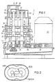
- the exemplary embodiment shown in FIG. 1 is a three-stage vacuum pump 1 with two shafts 2 and 3 and three pairs of rotors 4, 5 or 6, 7 or 8, 9.
- the axial length of the rotors decreases from the suction side to the pressure side .
- the rotary pistons are of the claw type (see FIG. 2) and rotate in the scoops 11, 12, 13, which are formed by the shields or side walls 14 to 17 and the housing rings 18 to 20.
- the shafts 2, 3 are arranged vertically. This also applies to the drive motor 22 arranged next to the pump housing. Below the lower bearing plate 17, the shafts 2, 3 are equipped with gear wheels 23, 24 of the same diameter, which synchronize the movement of the rotor pairs 4, 5 or 6, 7 or 8 , 9 serve.
- the drive motor 22 also has a gearwheel 25 on its underside. The drive connection is established by a further gearwheel 26 which is in engagement with the gearwheels 24 and 25.
- the upper bearing wall 14 is equipped with a horizontally arranged connecting flange 28, which forms the inlet 29 of the pump.
- the inlet channel 31 opens at the end (opening 32) into the scoop chamber 11 of the first stage.
- the outlet opening of the first stage, which is arranged at the end, is designated 33 and leads into the connecting channel 34.
- the connecting channel 34 located in the wall 15 communicates with the second stage inlet port 35.
- the bearing wall 16 is designed accordingly. Below the lowest (third) pump stage is the outlet 36, which is connected to the front outlet opening 37 in the lower bearing wall 17.
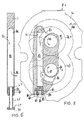
- the side wall 16 shown in FIGS. 3 to 6 serves to separate two scooping spaces 12, 13 of the claw pump 1.
- one (12) of the scooping spaces is above and the second scooping space (14) below the shield (16).
- the contour of the scoops 12, 13 is shown in dash-dot lines.
- the shafts 2, 3 carrying the rotors pass through the disk 16. Their direction of rotation is indicated by the arrows 49 and 51.
- the passage channel 52 is provided. It connects the outlet 53 of the scoop chamber 12 located on the front side to the inlet 54 of the scoop chamber 13 also located on the front side. Outlet 53 and inlet 54 are formed by arcuate cutouts in the disk 16.
- the channel 52 is formed by a blind bore 55 in the disk 16, which intersects the outlet 53 and the inlet 54 and thus establishes their connection.
- a sleeve 56 is inserted into the bore 55, which in particular in the region of the section that connects the outlet 53 and the inlet 54 forms the inner wall of the passage 52.
- Outlet 53 is assigned to the obliquely designed inner end face 57 of the sleeve 56, while the inlet 54 is assigned an opening 58 in the sleeve.
- the outer end face of the sleeve 56 is equipped with a plug 59.
- Sleeve 56 and plug 59 are welded together.
- the plug 59 serves to seal the outer opening of the blind bore 55.
- the plug is equipped with the radial sealing ring 61.
- the plug has a thread 62 which is accessible from the outside. This thread 62 receives a screw 63 with which a bolt 64 is fastened on the stopper 59.
- the plug 59 is equipped with the edge 65. With the help of a further screw 66, the bolt 64 is fastened to the disk 16.
- the invention has been described with the aid of a multi-stage vacuum pump of the claw type, the stages of which have inlets and outlets located on the end face.
- the inlets and outlets are usually peripheral. Your connecting channels therefore have different directions than with claw pumps.
- the possibility of providing them with a sleeve 56 according to the invention is, however, independent of the direction of the channels.
- FIGS. 5 and 6 show exemplary embodiments in which - as in the other exemplary embodiments - the connecting channel 52 is part of an outwardly leading bore 55 in the side wall 16.
- the bore 55 is closed with the plug 59.
- the connecting channel 52 is suitable for inspections, e.g. with the help of an endoscope, accessible without disassembly.
- FIG. 6 shows a variant in which the stopper 59 is provided with a longitudinal bore 67 in which there is a pipe section 68 leading to the outside.
- the outer end of the pipe section 68 is provided with a flange 69, on which a blind flange 70 is placed in a vacuum-tight manner in the exemplary embodiment shown.
- holders for sensors inserted into the connecting channel 52 can be attached to the flange 69 in a vacuum-tight manner.
Landscapes
- Engineering & Computer Science (AREA)
- Mechanical Engineering (AREA)
- General Engineering & Computer Science (AREA)
- Applications Or Details Of Rotary Compressors (AREA)
- Compressors, Vaccum Pumps And Other Relevant Systems (AREA)
Description
- Die Erfindung bezieht sich auf eine mehrstufige Vakuumpumpe mit einem Gehäuse, mit mindestens zwei Schöpfräumen in dem Gehäuse und mit einem die Schöpfräume miteinander verbindenden Kanal.
- Mehrstufige Vakuumpumpen sind aus der DE-A 3147824 sowie der DE-A 3244099 bekannt. Werden Pumpen dieser oder ähnlicher Art zur Evakuierung von Kammern eingesetzt, in denen Ätz-, Beschichtungs- oder andere Vakuumbehandlungs- oder -herstellverfahren durchgeführt werden, dann geschieht es häufig, daß Feststoffe in die Pumpe gelangen. Es besteht sogar die Möglichkeit, daß solche Feststoffe erst während der Verdichtung der Gase, also während des Durchtritts der abzupumpenden Gase durch die Vakuumpumpe entstehen. Beispiele sind die Entstehung von Aluminium-Chlorid beim Aluminium-Ätzen, Amoniumchlorid bei Beschichtungsverfahren usw.
- Lagern sich Stoffe dieser Art in den Durchtrittskanälen für das zu evakuierende Gas ab, dann verringert sich der Durchmesser dieser Kanäle, was eine Reduzierung der Leistung der Vakuumpumpe zur Folge hat. Die Feststellung einer beginnenden Verschmutzung setzt eine Demontage der Pumpe voraus, welche aufwendig und deshalb teuer ist.
- Der vorliegenden Erfindung liegt die Aufgabe zugrunde, eine Vakuumpumpe der eingangs genannten Art zu schaffen, bei der die Feststellung und Beseitigung von Verschmutzungen der gefährdeten Durchtrittskanäle besonders einfach ist.
- Erfindungsgemäß wird diese Aufgabe dadurch gelöst, daß der Kanal in an sich bekannter Weise Teil einer nach außen führenden Bohrung ist, die mit einem Stopfen verschließbar ist, daß am Stopfen eine Hülse befestigt ist, welche zumindest einen Teil der Innenwandung des Verbindungskanals bildet und daß die Hülse mit Öffnungen bzw. Durchbrechungen ausgerüstet ist, welche dem Ein- und Austritt der durch den Verbindungskanal strömenden Medien dienen. Diese Lösung erlaubt es, den oder die Verbindungskanäle ohne Demontage der Pumpe zu inspizieren. Durch die nach außen führende Mündung der Bohrung kann die Hülse, in der sich die Feststoffe ablagern, herausgenommen und entweder gereinigt oder durch eine neue Hülse ersetzt werden. Die Reinigung kritischer Bereiche von Durchtrittskanälen ist damit besonders einfach.
- Aus der US-A-1626484 ist zwar eine Gasförderpumpe mit zwei Druckräumen bekannt, bei der der Verbindungskanal Teil einer nach außen führenden und mit einem Stopfen verschließbaren Bohrung ist. Bei dieser Pumpe handelt es sich jedoch nicht um eine Vakuumpumpe. Außerdem dient der Verbindungskanal dem Anschluß einer Zuführungsleitung für Öl, das zerstäubt und dem zweiten Druckraum zugeleitet wird.
- Zweckmäßig ist der Stopfen mit einer Längsbohrung versehen, an die sich nach außen ein mit einem Flansch versehener Rohrabschnitt anschließt. Über den Flansch können z.B. Druck- oder Temperatur-Sensoren vakuumdicht in das Innere des Verbindungskanals eingeführt werden, so daß diese Parameter während des Betriebes überwacht werden können.
- Weitere Vorteile und Einzelheiten der Erfindung sollen anhand von in den Figuren 1 bis 6 dargestellten Ausführungsbeispielen erläutert werden. Es zeigen:
- ― Figur 1 einen Längsschnitt durch eine mehrstufige Pumpe nach der Erfindung mit nebeneinander angeordnetem Pumpengehäuse und Antriebsmotor,
- ― Figur 2 einen Schnitt durch ein Rotorpaar,
- ― Figur 3 und 5 jeweils einen Schnitt durch eine Seitenwand einer mehrstufigen Vakuumpumpe vom Klauentyp, senkrecht zur Drehachse der Rotoren und
- ― Figur 4 und 6 jeweils einen zum Schnitt nach den Figuren 3 bzw. 5 senkrechten Schnitt durch eine Seitenwand.
- Bei dem in Figur 1 dargestellten Ausführungsbeispiel handelt es sich um eine dreistufige Vakuumpumpe 1 mit zwei Wellen 2 und 3 sowie drei Rotorpaaren 4, 5 bzw. 6, 7 bzw. 8, 9. Die axiale Länge der Rotoren nimmt von der Saugseite zur Druckseite ab. Die Drehkolben sind vom Klauentyp (vgl. Figur 2) und rotieren in den Schöpfräumen 11, 12, 13, welche von den Schilden bzw. Seitenwänden 14 bis 17 und den Gehäuseringen 18 bis 20 gebildet werden.
- Die Wellen 2, 3 sind vertikal angeordnet. Dieses gilt ebenfalls für den neben dem Pumpengehäuse angeordneten Antriebsmotor 22. Unterhalb des unteren Lagerschildes 17 sind die Wellen 2, 3 mit Zahnrädern 23, 24 gleichen Durchmessers ausgerüstet, welche der Synchronisation der Bewegung der Rotorpaare 4, 5 bzw. 6, 7 bzw. 8, 9 dienen. Auch der Antriebsmotor 22 weist an seiner Unterseite ein Zahnrad 25 auf. Die Antriebsverbindung wird hergestellt durch ein weiteres Zahnrad 26, das mit den Zahnrädern 24 und 25 in Eingriff steht.
- In der oberen Lagerwand 14 und der unteren Lagerwand 17 stützen sich die Wellen 2, 3 über Wälzlager 27 ab. Die obere Lagerwand 14 ist mit einem horizontal angeordneten Anschlußflansch 28 ausgerüstet, welcher den Einlaß 29 der Pumpe bildet. Der Einlaßkanal 31 mündet stirnseitig (Öffnung 32) in den Schöpfraum 11 der ersten Stufe. Die stirnseitig angeordnete Auslaßöffnung der ersten Stufe ist mit 33 bezeichnet und führt in den Verbindungskanal 34. Der in der Wand 15 befindliche Verbindungskanal 34 steht mit der Einlaßöffnung 35 der zweiten Stufe in Verbindung. Die Lagerwand 16 ist entsprechend gestaltet. Unterhalb der untersten (dritten) Pumpstufe befindet sich der Auslaß 36, der mit der stirnseitigen Auslaßöffnung 37 in der unteren Lagerwand 17 in Verbindung steht.
- Die in den Figuren 3 bis 6 dargestellte Seitenwand 16 dient der Trennung von zwei Schöpfräumen 12, 13 der Klauenpumpe 1. Mit Bezug auf die in Figur 1 gewählte Darstellung liegt einer (12) der Schöpfräume oberhalb und der zweite Schöpfraum (14) unterhalb des Schildes (16). Die Kontur der Schöpfräume 12, 13 ist strichpunktiert dargestellt. In diesen Schöpfräumen 12, 13 befindet sich je ein Rotorpaar 6,7 bzw. 8, 9, dessen Konturen gestrichelt dargestellt sind. Die die Rotoren tragenden Wellen 2, 3 durchsetzen die Scheibe 16. Ihre Drehrichtung ist durch die Pfeile 49 und 51 angegeben.
- Um dem gepumpten Medium den Durchtritt von der hochvakuumseitigen Stufe mit dem Schöpfraum 12 oberhalb der Scheibe 16 zur vorvakuumseitigen Stufe mit dem Schöpfraum 13 unterhalb der Scheibe zu ermöglichen, ist der Durchtrittskanal 52 vorgesehen. Er verbindet den stirnseitig gelegenen Auslaß 53 des Schöpfraumes 12 mit dem ebenfalls stirnseitig gelegenen Einlaß 54 des Schöpfraumes 13. Auslaß 53 und Einlaß 54 werden von bogenförmigen Aussparungen in der Scheibe 16 gebildet.
- Der Kanal 52 wird von einer Sackbohrung 55 in der Scheibe 16 gebildet, die Auslaß 53 und Einlaß 54 schneidet und so deren Verbindung herstellt. Bei den Ausführungsbeispielen nach den Figuren 3 und 4 ist in die Bohrung 55 eine Hülse 56 eingeführt, die insbesondere im Bereich des Abschnittes, der Auslaß 53 und Einlaß 54 miteinander verbindet, die Innenwandung des Durchtrittskanales 52 bildet. Auslaß 53 ist der schräg gestalteten inneren Stirnseite 57 der Hülse 56 zugeordnet, während dem Einlaß 54 eine Durchbrechung 58 in der Hülse zugeordnet ist.
- Die äußere Stirnseite der Hülse 56 ist mit einem Stopfen 59 ausgerüstet. Hülse 56 und Stopfen 59 sind miteinander verschweißt. Zum einen dient der Stopfen 59 dem dichten Verschluß der äußeren Öffnung der Sackbohrung 55. Dazu ist er mit dem Radialdichtring 61 ausgerüstet. Weiterhin weist der Stopfen ein von außen zugängliches Gewinde 62 auf. Dieses Gewinde 62 nimmt eine Schraube 63 auf, mit der ein Riegel 64 auf dem Stopfen 59 befestigt ist. Um dem Riegel 64 eine definierte Position auf dem Stopfen 59 zu geben, ist der Stopfen 59 mit dem Rand 65 ausgerüstet. Mit Hilfe einer weiteren Schraube 66 ist der Riegel 64 an der Scheibe 16 befestigt.
- Fallen während des Betriebes des Pumpe 1 Feststoffverschmutzungen an, dann lagern sich diese bevorzugt im Durchtrittskanal 52 ab. Um diesen zu reinigen, genügt es in der Regel, die Schraube 66 zu lösen, die Hülse 56 herauszuziehen und zu reinigen oder durch eine neue zu ersetzen. Läßt sich die Hülse nicht ohne weiteres bewegen, dann besteht die Möglichkeit, auch die Schraube 63 zu lösen und in das Gewinde 62 ein Werkzeug einzusetzen, mit dessen Hilfe festsitzende Hülsen unter Aufwendung größerer Kraft gelöst und herausgezogen werden können. Nach der Reinigung wird wieder der Riegel 64 mit der Schraube 63 auf dem Stopfen 59 befestigt. Die gereinigte Hülse 56 wird in die Bohrung 55 eingeschoben. Danach wird der Riegel 64 mit Hilfe der Schraube 66 an der Scheibe 16 befestigt. Die Position dieser Schraube 66 und der Rand 65 am Stopfen 59 sichern die richtige Lage der Hülse 56 in der Bohrung 55, d.h. daß die schräge Stirnseite 57 der Hülse 56 dem Auslaß 53 und die Durchbrechung 58 dem Einlaß 54 zugeordnet sind.
- Die Erfindung ist anhand einer mehrstufigen Vakuumpumpe vom Klauentyp beschrieben worden, deren Stufen stirnseitig gelegene Ein- und Auslässe haben. Bei anderen Vakuumpumpentypen liegen die Einlässe und Auslässe in der Regel peripher. Ihre Verbindungskanäle haben deshalb andere Richtungen als bei Klauenpumpen. Von der Richtung der Kanäle ist jedoch die Möglichkeit, diese mit einer erfindungsgemäßen Hülse 56 zu versehen, unabhängig.
- Die Figuren 5 und 6 zeigen Ausführungsbeispiele, bei denen ― wie bei den übrigen Ausführungsbeispielen ― der Verbindungskanal 52 Teil einer nach außen führenden Bohrung 55 in der Seitenwand 16 ist. Die Bohrung 55 ist mit dem Stopfen 59 verschlossen. Nach dem Entfernen des Stopfens 59 ist der Verbindungskanal 52 für Inspektionen, z.B. mit Hilfe eines Endoskopes, zugänglich, ohne daß eine Demontage erforderlich ist.
- Figur 6 zeigt eine Variante, bei der der Stopfen 59 mit einer Längsbohrung 67 versehen ist, in sich der ein nach außen führender Rohrabschnitt 68 befindet. Das äußere Ende des Rohrabschnittes 68 ist mit einem Flansch 69 versehen, auf den beim dargestellten Ausführungsbeispiel ein Blindflansch 70 vakuumdicht aufgesetzt ist. Statt eines Blindflansches 70 können Halterungen für in den Verbindungskanal 52 eingeführte Sensoren am Flansch 69 vakuumdicht befestigt sein.
Claims (8)
Priority Applications (2)
| Application Number | Priority Date | Filing Date | Title |
|---|---|---|---|
| US07/313,165 US4943215A (en) | 1988-02-29 | 1989-02-17 | Multistage vacuum pump with bore for fouling removal |
| JP1036453A JPH01247787A (ja) | 1988-02-29 | 1989-02-17 | 多段真空ポンプ |
Applications Claiming Priority (2)
| Application Number | Priority Date | Filing Date | Title |
|---|---|---|---|
| EP88102986 | 1988-02-29 | ||
| EP88102986 | 1988-02-29 |
Publications (2)
| Publication Number | Publication Date |
|---|---|
| EP0332741A1 EP0332741A1 (de) | 1989-09-20 |
| EP0332741B1 true EP0332741B1 (de) | 1991-09-18 |
Family
ID=8198761
Family Applications (1)
| Application Number | Title | Priority Date | Filing Date |
|---|---|---|---|
| EP88117706A Expired - Lifetime EP0332741B1 (de) | 1988-02-29 | 1988-10-25 | Mehrstufige Vakuumpumpe |
Country Status (2)
| Country | Link |
|---|---|
| EP (1) | EP0332741B1 (de) |
| DE (1) | DE3865009D1 (de) |
Families Citing this family (3)
| Publication number | Priority date | Publication date | Assignee | Title |
|---|---|---|---|---|
| JP2537696B2 (ja) * | 1990-09-21 | 1996-09-25 | 株式会社荏原製作所 | 多段真空ポンプ |
| GB9902083D0 (en) * | 1999-01-29 | 1999-03-24 | Boc Group Plc | Vacuum pump systems |
| DE10019066A1 (de) * | 2000-04-18 | 2001-10-25 | Leybold Vakuum Gmbh | Vakuumpumpe mit zwei zusammenwirkenden Rotoren |
Citations (1)
| Publication number | Priority date | Publication date | Assignee | Title |
|---|---|---|---|---|
| DE2158866A1 (de) * | 1971-11-27 | 1973-05-30 | Engstfeld Wilh Fa | Vorrichtung zum entgasen von metallschmelzen |
Family Cites Families (8)
| Publication number | Priority date | Publication date | Assignee | Title |
|---|---|---|---|---|
| US1854318A (en) * | 1926-06-17 | 1932-04-19 | Westinghouse Electric & Mfg Co | Compressor |
| US1626484A (en) * | 1926-11-24 | 1927-04-26 | James Mccaffrey R | Pump |
| GB315365A (de) * | 1928-07-12 | 1930-02-06 | Gebrueder Ludwig | |
| GB531798A (en) * | 1939-08-02 | 1941-01-10 | Siemens Brothers & Co Ltd | Improvements in or relating to electrical filter networks |
| FR1120279A (fr) * | 1955-01-24 | 1956-07-03 | Groupe compresseur hermétique | |
| DE2158868B2 (de) * | 1971-11-27 | 1975-12-04 | Gebr. Claas, 4834 Harsewinkel | Maschine zum Zerkleinern von sperrigen Abfällen |
| US3837764A (en) * | 1972-05-11 | 1974-09-24 | Robinair Mfg Corp | Multi-stage rotary vacuum pump with separate oil reservoir |
| DE2503020A1 (de) * | 1975-01-25 | 1976-07-29 | Wikotool Syst Tech Maschbau | Drehkolbenmaschine sowie verfahren zu ihrer herstellung |
-
1988
- 1988-10-25 DE DE8888117706T patent/DE3865009D1/de not_active Expired - Fee Related
- 1988-10-25 EP EP88117706A patent/EP0332741B1/de not_active Expired - Lifetime
Patent Citations (1)
| Publication number | Priority date | Publication date | Assignee | Title |
|---|---|---|---|---|
| DE2158866A1 (de) * | 1971-11-27 | 1973-05-30 | Engstfeld Wilh Fa | Vorrichtung zum entgasen von metallschmelzen |
Also Published As
| Publication number | Publication date |
|---|---|
| DE3865009D1 (de) | 1991-10-24 |
| EP0332741A1 (de) | 1989-09-20 |
Similar Documents
| Publication | Publication Date | Title |
|---|---|---|
| EP0408791B1 (de) | Reibungspumpe mit glockenförmigem Rotor | |
| DE69403818T3 (de) | Zellenradschleuse | |
| EP3754200B1 (de) | Scrollvakuumpumpe und montageverfahren | |
| EP0156951B1 (de) | Zweiwellen-Vakuumpumpe mit Getrieberaum-Evakuierung | |
| DE69206051T2 (de) | Motorgetriebenes Pumpensystem. | |
| DE69529369T2 (de) | Spiralverdichter mit effektiver trennung von öl aus verdichtetem gas | |
| EP3974655B1 (de) | Scrollvakuumpumpe und ihr herstellungsverfahren | |
| DE3614144A1 (de) | Kreiselverdichter | |
| DE3445014A1 (de) | Schalldaempfer fuer motorkompressoren | |
| EP0365695B1 (de) | Zweiwellenvakuumpumpe mit Schöpfraum | |
| CH656676A5 (de) | Waelzkolbenpumpe mit druckausgleichskammer. | |
| DE69119183T2 (de) | Kreiselpumpe mit Abdichtungsmitteln | |
| EP0663986B1 (de) | Trockenverdichtende vakuumpumpe | |
| EP1597556A1 (de) | Testgaslecksuchgerät | |
| DE10150015A1 (de) | Mehrkammeranlage zur Behandlung von Gegenständen unter Vakuum, Verfahren zur Evakuierung dieser Anlage und Evakuierungssystem dafür | |
| EP0332741B1 (de) | Mehrstufige Vakuumpumpe | |
| EP3112688B2 (de) | Splitflow-vakuumpumpe sowie vakuum-system mit einer splitflow-vakuumpumpe | |
| EP3708840B1 (de) | Vakuumpumpe mit rückschlagventil | |
| DE1957005A1 (de) | OElabsaugpumpe und Antriebsvorrichtung fuer Zusatzaggregate | |
| DE3445400A1 (de) | Oelabscheider | |
| DE19809957A1 (de) | Mehrwellenvakuumpumpe | |
| DE60313841T2 (de) | Schraubenverdichter mit in-line Öl-Abscheider | |
| DE19901340A1 (de) | Reibungsvakuumpumpe mit Chassis, Rotor und Gehäuse sowie Einrichtung, ausgerüstet mit einer Reibungsvakuumpumpe dieser Art | |
| DE9014888U1 (de) | Schalldämpfer | |
| EP0566573B1 (de) | Schalldämpfer |
Legal Events
| Date | Code | Title | Description |
|---|---|---|---|
| PUAI | Public reference made under article 153(3) epc to a published international application that has entered the european phase |
Free format text: ORIGINAL CODE: 0009012 |
|
| AK | Designated contracting states |
Kind code of ref document: A1 Designated state(s): DE FR GB |
|
| 17P | Request for examination filed |
Effective date: 19900315 |
|
| 17Q | First examination report despatched |
Effective date: 19900709 |
|
| GRAA | (expected) grant |
Free format text: ORIGINAL CODE: 0009210 |
|
| AK | Designated contracting states |
Kind code of ref document: B1 Designated state(s): DE FR GB |
|
| GBT | Gb: translation of ep patent filed (gb section 77(6)(a)/1977) | ||
| REF | Corresponds to: |
Ref document number: 3865009 Country of ref document: DE Date of ref document: 19911024 |
|
| ET | Fr: translation filed | ||
| PLBE | No opposition filed within time limit |
Free format text: ORIGINAL CODE: 0009261 |
|
| STAA | Information on the status of an ep patent application or granted ep patent |
Free format text: STATUS: NO OPPOSITION FILED WITHIN TIME LIMIT |
|
| 26N | No opposition filed | ||
| PGFP | Annual fee paid to national office [announced via postgrant information from national office to epo] |
Ref country code: FR Payment date: 19930914 Year of fee payment: 6 |
|
| PGFP | Annual fee paid to national office [announced via postgrant information from national office to epo] |
Ref country code: GB Payment date: 19930916 Year of fee payment: 6 |
|
| PGFP | Annual fee paid to national office [announced via postgrant information from national office to epo] |
Ref country code: DE Payment date: 19930920 Year of fee payment: 6 |
|
| PG25 | Lapsed in a contracting state [announced via postgrant information from national office to epo] |
Ref country code: GB Effective date: 19941025 |
|
| GBPC | Gb: european patent ceased through non-payment of renewal fee |
Effective date: 19941025 |
|
| PG25 | Lapsed in a contracting state [announced via postgrant information from national office to epo] |
Ref country code: FR Effective date: 19950630 |
|
| PG25 | Lapsed in a contracting state [announced via postgrant information from national office to epo] |
Ref country code: DE Effective date: 19950701 |
|
| REG | Reference to a national code |
Ref country code: FR Ref legal event code: ST |