EP0332588A2 - Verfahren und Vorrichtung zum Abrichten der vier Oberflächen eines quaderförmigen Holzstückes - Google Patents
Verfahren und Vorrichtung zum Abrichten der vier Oberflächen eines quaderförmigen Holzstückes Download PDFInfo
- Publication number
- EP0332588A2 EP0332588A2 EP89830089A EP89830089A EP0332588A2 EP 0332588 A2 EP0332588 A2 EP 0332588A2 EP 89830089 A EP89830089 A EP 89830089A EP 89830089 A EP89830089 A EP 89830089A EP 0332588 A2 EP0332588 A2 EP 0332588A2
- Authority
- EP
- European Patent Office
- Prior art keywords
- cutter
- work
- surfacing
- planing tool
- face
- Prior art date
- Legal status (The legal status is an assumption and is not a legal conclusion. Google has not performed a legal analysis and makes no representation as to the accuracy of the status listed.)
- Withdrawn
Links
Images

Classifications
-
- B—PERFORMING OPERATIONS; TRANSPORTING
- B27—WORKING OR PRESERVING WOOD OR SIMILAR MATERIAL; NAILING OR STAPLING MACHINES IN GENERAL
- B27D—WORKING VENEER OR PLYWOOD
- B27D1/00—Joining wood veneer with any material; Forming articles thereby; Preparatory processing of surfaces to be joined, e.g. scoring
-
- B—PERFORMING OPERATIONS; TRANSPORTING
- B27—WORKING OR PRESERVING WOOD OR SIMILAR MATERIAL; NAILING OR STAPLING MACHINES IN GENERAL
- B27F—DOVETAILED WORK; TENONS; SLOTTING MACHINES FOR WOOD OR SIMILAR MATERIAL; NAILING OR STAPLING MACHINES
- B27F5/00—Slotted or mortised work
- B27F5/02—Slotting or mortising machines tools therefor
- B27F5/026—Slotting a workpiece before introducing into said slot a guide which belongs to a following working device, and which is parallel to the feed movement of this working device
-
- B—PERFORMING OPERATIONS; TRANSPORTING
- B27—WORKING OR PRESERVING WOOD OR SIMILAR MATERIAL; NAILING OR STAPLING MACHINES IN GENERAL
- B27C—PLANING, DRILLING, MILLING, TURNING OR UNIVERSAL MACHINES FOR WOOD OR SIMILAR MATERIAL
- B27C1/00—Machines for producing flat surfaces, e.g. by rotary cutters; Equipment therefor
- B27C1/06—Machines for smoothing and subsequent thicknessing
-
- B—PERFORMING OPERATIONS; TRANSPORTING
- B27—WORKING OR PRESERVING WOOD OR SIMILAR MATERIAL; NAILING OR STAPLING MACHINES IN GENERAL
- B27C—PLANING, DRILLING, MILLING, TURNING OR UNIVERSAL MACHINES FOR WOOD OR SIMILAR MATERIAL
- B27C1/00—Machines for producing flat surfaces, e.g. by rotary cutters; Equipment therefor
- B27C1/08—Machines for working several sides of work simultaneously
-
- B—PERFORMING OPERATIONS; TRANSPORTING
- B27—WORKING OR PRESERVING WOOD OR SIMILAR MATERIAL; NAILING OR STAPLING MACHINES IN GENERAL
- B27G—ACCESSORY MACHINES OR APPARATUS FOR WORKING WOOD OR SIMILAR MATERIALS; TOOLS FOR WORKING WOOD OR SIMILAR MATERIALS; SAFETY DEVICES FOR WOOD WORKING MACHINES OR TOOLS
- B27G19/00—Safety guards or devices specially adapted for wood saws; Auxiliary devices facilitating proper operation of wood saws
- B27G19/10—Measures preventing splintering of sawn portions of wood
Definitions
- the invention relates to a method of truing-up the four faces of a piece of wood exhibiting squared cross section, and a relative machine unit.
- the art field of woodworking machinery embraces a type of unit by which workpieces, and typically, longitudinal battens of essentially regular initial section, can be trued up and planed to size.
- the operation of truing and surfacing a workpiece of squared section consists in removing wood from its four longitudinal faces by mechanical means. This done, i.e. with the cross-sectional dimensions being substantially to final requirements and the profile faultlessly square or rectangular, the work can be conveyed forward to successive tool stations where it is finished off and moulded to a given shape, or matched to other components and glued.
- the workpiece might be tenoned, for example, in readiness for assembly as part of a door or window fixture, in which case the final step will be that of rounding off certain of the longitudinal edges, or sinking mortises in one or more of the faces.
- Conventional machinery, equipment or units for truing-up the four faces of square-section work substantially comprise four planing tools, located in sequence along the path followed by the work: one beneath, with a horizontally disposed axis; one on the right flank with a vertically disposed axis; one of the left flank, also vertical; and a final horizontal tool positioned over the work, in short: bottom horizontal, vertical right, vertical left and top horizontal.
- Such a unit includes two tables, one on either side of the bottom tool (preceding and beyond), and a system of power driven feed rollers located above and operating in conjunction with the table beyond the bottom planar.
- the bottom face is planed to provide a reference for the remaining steps of the procedure; the work then passes onto the second table, which is aligned with the crest of the rotating bottom planar tool, and into contact with the overhead feed rollers which propel it forward through the tool stations that plane the right and the left faces and the top.
- the various tools and feed systems are driven by individual respective motors, or, less typically, the tools are driven in pairs by one horizontally disposed and one vertically disposed motor.
- Machines of the type thus outlined are beset by the drawback of a limited range of working adjustment, however, and of the fact that the finish produced on the right and left hand faces is not well suited to receive glue, should the workpiece be destined for subsequent bonding.
- the vertical tools in these conventional machines are planers, just like the horizontal tools, and both produce a final surface that is smooth, and undulated through given stretches.
- the surface best suited for bonding is that cut by a blade, i.e by a saw blade: a sawn cut does not compress the pores of the timber in the same way as a planing pass; instead, the surface is roughened, and thus better able to absorb the adhesive applied to it in correct fashion. Moreover, the undulations left by planing permit the formation of a film of glue between matched and bonded surfaces, which is visible from the outside and spoils the appearance of the finished item.
- the object of the present invention is to set forth a method of truing the four faces of a piece of wood in such a way as to ensure that no splinters are produced, as that the side faces of any two pieces are rendered suitable for bonding with adhesive one to another, whilst retaining the levels of accuracy currently obtainable with a unit of conventional design.
- Another object of the invention gained by adoption of the constructional design of a unit as envisaged herein, is to provide machinery of singularly low manufacturing and running cost, ensured not least by virtue of its low power specification.
- All the tool shafts in the unit are belt-driven from one motor, and the top planer is supported at each end by a horizontally mobile slide that can be traversed across the path followed by the work, and adjusted for vertical position.
- a first advantage of the invention stems from the compact design of the machine unit, achieved not least as a result of adopting a drive utilizing just one motor.
- Single motor drive also provides a significant advantage in terms of cost, especially for small joinery and craft concerns where the overall running time of the machine will generally far outweigh its effective operating time with the one-motor machine unit disclosed, in effect, time spent in the idle power-on state is less costly to the user than would be the case with a multi-motor unit.
- Another advantage of the machine unit disclosed is that of the ease with which adjustments can be made to accommodate the varying dimensions of different work put through, simply by traversing and raising or lowering the slide to set the position of the left hand cutter and the top horizontal planer.
- Yet another advantage of the invention is that it provides the option, in the case of the right and left hand tools, at least, of utilizing detachable and reversible cutter inserts for better finishing and greater durability.
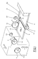
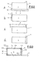
- the method according to the invention for truing-up the four faces of a piece of wood 1 comprises the steps of: -surfacing the bottom face 1i by means of a bottom horizontal axis planing tool 2; -squaring the bottom edge of one side face 1d by means of a first horizontal axis trimming cutter 6 associated with the bottom planing tool 2; -surfacing at least the remaining area of the same side face 1d by means of a first horizontal axis cutter 3, the vertical face of which occupies the same plane as that occupied by the vertical face of the first trimming cutter 6; -surfacing the top face 1a with a top horizontal axis planing tool 4; -surfacing the remaining side face 1s by means of a second horizontal axis cutter 5:
- the two trimming cutters 6 and 7 will be embodied integrally with the respective planing tools 2 and 4, as discernable from figs 1 and 2. Accordingly, the steps of planing the bottom face 1i and trimming the bottom edge of the right hand side face 1d will be effected simultaneously, as also will be the steps of planing the top face 1a and trimming the top edge of the left hand side face 1s. Adopting the method disclosed, moreover, the side faces 1d and 1s of the work 1 are surfaced with a radial cutting action the effects of which are identical to those of a sawn cut, and namely, such as to produce degrees of surface roughness and porosity that will enable battens to be matched and glued together faultlessly one with the next.
- a machine unit for implementation of the method disclosed essentially comprises: -a horizontal axis bottom planing tool 2; -a first horizontal axis trimming cutter 6; -a first horizontal axis surfacing cutter 3; -a horizontal axis top planing tool 4; -a second horizontal axis trimming cutter 7; -a second horizontal axis surfacing cutter 5; -feed means 24, with axis horizontally disposed; -two work tables 8 and 9 located at dissimilar heights one on either side of the bottom planing tool 2, preceding and beyond, respectively, in relation to the path f of the work, of which the second table 9 occupies the same plane as that occupied by the topmost crest of the bottom planing tool 2, and is the higher table of the two; -a first side fence 12 positioned in alignment with and located beyond the first trimming cutter 6, and a second side fence 10 aligned with and beyond the first surfacing cutter 3.
- the two cutters 3 and 6 on the one side must be positioned in mutual alignment, at least inasmuch as their relative vertical cutting faces 31 and 61 must be aligned, and the same applies in the case of the cutters 5 and 7 at the remaining side.
- the first trimming cutter 6 will be integral with the end of the bottom planing tool 2, and the second trimming cutter 7 with the end of the top planing tool 4; needless to say, the two cutters 6 and 7 occupy positions at opposite sides of the table 8 so as to engage the right and left hand faces of the work 1, respectively.
- the bottom planing tool 1 may be referred to throughout as the bottom horizontal tool, the first surfacing cutter 3 as vertical Rx, the top planing tool 4 as top horizontal, and the second surfacing cutter 5 as vertical Lx.
- the reference is used essentially to distinguish the right hand side 1d and the left hand side 1s of the work (see fig 2) fed into the unit.
- the first work table 8 is supported by a base 15, adjustable for height to allow of varying the depth of cut effected with the bottom horizontal tool 2, and provided with an adjustable fence 8a located on the same side as the fences 10 and 12 mentioned above; more exactly, the fence 8b in question can be offset transversely from the first fence 12 through a distance, measured along the axis of the bottom horizontal tool 2, that corresponds to the thickness of the wood to be removed from the right hand face 1d of the work 1.
- the vertical Rx tool 3 is carried by an extension 15a of the base 15, fitted to a spindle 31 that can be adjusted axially for the purposes of aligning the tool 3 with the right hand trimming cutter 6 (fig 4).
- the height at which the vertical Rx tool 3 is set will be such that the area of the face 1d cleared by its cutting action overlaps a short vertical distance, denoted S1 in fig 3, with the bottom part prepared previously by the trimming cutter 6.
- the edge of the face 1d is rendered true, and accurate finishing is ensured by the radial action of the cutter 3; thus, the bottom face 1i emerges from the cut free of the splinters which would be produced were the vertical Rx tool 3 to engage the full width of the side face 1d.
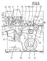
- top horizontal tool 4 and vertical Lx tool 5 are both overhung, mounted directly and by way of an axially adjustable spindle 32, respectively, to a horizontal slide 14 of hollow parallelepiped embodiment, capable of traversing horizontally left and right across the path f of the workpieces 1 in the direction of the arrow denoted f2; the slide 14 runs on ways 16 integral with the top of a knee 36 at the rear of the machine, which is carried by and capable of traversing vertically in relation to the base 15.
- Fig 5 provides a schematic illustration of the slide 14 and its ways 16 from the standpoint denoted V, showing their matching dovetail profile; the assembly will also include conventional drive and clamping means, which are not illustrated in the interests of simplicity.
- feed means 24 consisting in a plurality of power driven rollers rotatable about horizontal axes, which operate in conjunction with the second table 9.
- feed means 24 consisting in a plurality of power driven rollers rotatable about horizontal axes, which operate in conjunction with the second table 9.
- two such rollers 24 only are illustrated in fig 1, preceding and beyond the vertical Rx tool 3; in practice however, the number could be greater, for example as shown in fig 6.
- Such rollers would be rubber face, if installed beyond the top planing tool 4, and perhaps serrated in the case of rollers preceding the same tool 4, this being a distinction that would need to be observed in view of the fact that the top face 1a remains unfinished prior to passing beneath the top tool 4, whereas beyond the tool, the surfaced and thicknessed work must not be exposed to potentially damaging mechanical pressures.
- the left hand end of the slide 14 exhibits an L-shaped bracket 51 affording a pair of vertical sockets 52; these serve to accommodate relative posts 53, the bottom ends of which rigidly associated with a horizontal plate 54 that rests permanently on the table 9 beneath by reason of its own weight, and thus serves advantageously as a mounting for the left hand support rail 25b, which embraces the vertical Lx tool 5 as illustrated in fig 6, in particular.
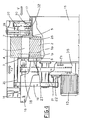
- the various tools 2, 3, 4 and 5 are driven from a single motor 13 anchored to and housed within the base 15, as also are the work feed rollers 24 (the transmission to the rollers is not illustrated). Drive is transmitted to the tools 2, 3, 4 and 5 by way of belts, which in a preferred embodiment will be of a flat type (see fig 5).
- 26 denotes a pulley keyed to the shaft of the motor 13, around which a first flat belt 18 is looped; the belt 18 is passed around a second pulley 27 keyed to the bottom horizontal tool 2, then around a take-off pulley 21 and a further pulley 28 keyed to the vertical Rx tool 3 before returning to the motor.
- 19 denotes a second flat belt, driven from the take-off pulley 21 (in effect, an overhung shaft), which is looped around a return pulley 22 carried by the knee 36 then around a pulley 29 keyed to the top horizontal tool 4, passing in addition over intermediate idlers 23 carried by the base 15.
- 20 denotes a third flat belt, looped around the top pulley 29 and a pulley 30 keyed to the vertical Lx tool 5, which passes over an idle pulley 34 carried by the cross slide 14.
- top pulley 29 is one and the same as a long transverse shaft passing through the relative horizontal tool 4; thus, the entire assembly of slide 14 and tools 4 and 5 can be traversed bodily along the ways 16 with the motor 13 running, given that the relative belt 19 is flat, and the axially mobile shaft 29 has no difficulty in slipping through the loop.
- the manner in which the second belt 19 is looped also enables the top and return pulleys 29 and 22 to shift vertically in relation to the idlers 23 and the take-off pulley 21, without any variation occurring in the overall length of the loop.
- Figs 1 and 5 illustrate how the bottom horizontal and the vertical Rx tools 2 and 3 are driven by the one belt 18, both the relative pulleys 27 and 28 being engaged by the inside face of the belt, and thus rotating in the same direction V1.
- the expedient of the transverse gap 17 is adopted.
- the vertical Lx tool 5 needs to drop almost completely below the level of the table 9, with its topmost crest positioned just below the finished top face of the work 1p (phantom line 5p). Accordingly, the dimensions of the gap 17 will be generous enough to permit handling work both of reduced thickness, and of notable width.
- the gap 17 dictates the need for the rails 25a and 25b, which are located alongside the side fence 10 and the vertical Lx tool 5, respectively; without the rails, the work 1 would not be supported from beneath, and distortion could well occur under the bending and twisting action of the tool, most notably on the left flank. It will be observed, in fact, that if work 1 of greater than 100mm thickness is to be surfaced, the diameter of the vertical Lx tool 5 will need to be larger, and the width of the gap 17 larger still. In order to permit of surfacing particularly thin work, the first trimming cutter 6 will project no further than 10 mm from the bottom planing tool 2, and the second trimming cutter 7 no further than 5mm from the top planing tool 4. Accordingly, the first side fence 12 will stand no higher than 9mm approx from the work table 9.
- the operator Before truing-up the four faces of a given piece 1 with a machine unit thus embodied, the operator will first select the height of the first table 8 in relation to the crest of the bottom horizontal tool 2, according to the depth of material to be removed from the bottom face 1i (Q1, in fig 3), and then set the distance between the fences 8a and 12 according to the depth of cut required at the right hand side face 1d (Q2, in fig 3). This done, the cross slide 14 is traversed along the ways 16, and the knee 36 adjusted for height, to give the final width and thickness of the finished piece 1.
- the unit is ready to operate, and the work 1 will emerge thicknessed to a depth equal to the distance between the top and bottom crests of the bottom and top planing tools 2 and 4, and to a width equal to the distance between the opposed vertical faces of the right and left hand surfacing cutters 3 and 5.
- the single workpiece 1 is offered to the table 8 with one side against the relative side fence 8a and pushed toward the bottom horizontal tool 2-6, which duly engages the bottom face 1i (see fig 2a) and the bottom right hand edge 1dl, removing the section denoted 33a in fig 3.
- the work 1 encounters the feed rollers 24, which carry it forward along the second table 9 with the trimmed edge 1dl of the right hand side face 1d flush against the relative fence 12; accordingly, the piece 1 is properly positioned even at this comparatively early stage, given that one finished and squared edge 1dl registers firmly in contact with two corresponding and mutually perpendicular reference surfaces.
- the top face 1a of the work is surfaced by the relative horizontal tool 4 (fig 2c), which will remove the section denoted 33c in fig 3, whereupon the final pass (fig 2d) is made by the vertical Lx tool 5 to remove the section denoted 33d in fig 3.
- These two sections 33c and 33d likewise overlap for a short depth (S2), which is cleared initially by the Lx trimming cutter 7 in readiness for passage of the Lx surfacing cutter 5.
Landscapes
- Life Sciences & Earth Sciences (AREA)
- Engineering & Computer Science (AREA)
- Mechanical Engineering (AREA)
- Wood Science & Technology (AREA)
- Forests & Forestry (AREA)
- Milling, Drilling, And Turning Of Wood (AREA)
- Dovetailed Work, And Nailing Machines And Stapling Machines For Wood (AREA)
Applications Claiming Priority (2)
| Application Number | Priority Date | Filing Date | Title |
|---|---|---|---|
| IT03364/88A IT1221235B (it) | 1988-03-09 | 1988-03-09 | Metodo e gruppo per il raddrizzamento su quattro lati di pezzi di lagno a sezione quadrangolare |
| IT336488 | 1988-03-09 |
Publications (2)
| Publication Number | Publication Date |
|---|---|
| EP0332588A2 true EP0332588A2 (de) | 1989-09-13 |
| EP0332588A3 EP0332588A3 (de) | 1991-06-12 |
Family
ID=11105743
Family Applications (1)
| Application Number | Title | Priority Date | Filing Date |
|---|---|---|---|
| EP19890830089 Withdrawn EP0332588A3 (de) | 1988-03-09 | 1989-02-28 | Verfahren und Vorrichtung zum Abrichten der vier Oberflächen eines quaderförmigen Holzstückes |
Country Status (7)
| Country | Link |
|---|---|
| US (1) | US4932448A (de) |
| EP (1) | EP0332588A3 (de) |
| JP (1) | JPH01275001A (de) |
| KR (1) | KR890014222A (de) |
| AU (1) | AU603287B2 (de) |
| BR (1) | BR8901076A (de) |
| IT (1) | IT1221235B (de) |
Cited By (2)
| Publication number | Priority date | Publication date | Assignee | Title |
|---|---|---|---|---|
| EP0430070A3 (en) * | 1989-11-30 | 1991-09-18 | Wilhelm Hirsch | Method and milling machine for simultaneous longitudinal profiling of glazing bars |
| AT404445B (de) * | 1994-01-15 | 1998-11-25 | Martin Otto Maschbau Gmbh | Hobelmaschine für das mehrseitige bearbeiten von holzwerkstücken |
Families Citing this family (10)
| Publication number | Priority date | Publication date | Assignee | Title |
|---|---|---|---|---|
| US5771949A (en) * | 1996-06-05 | 1998-06-30 | Black & Decker Inc. | Portable wood planing machine |
| US5927357A (en) * | 1997-12-30 | 1999-07-27 | Black & Decker Inc. | Portable wood planing machine |
| US5620033A (en) * | 1995-12-21 | 1997-04-15 | Chiu Ting Machinery Co., Ltd | Workpiece delivering device usable as a handle for a machine |
| DE19756280C2 (de) * | 1997-12-18 | 2000-11-23 | Weinig Michael Ag | Kehlmaschine sowie Werkzeug für eine Kehlmaschine |
| US6086461A (en) * | 1999-10-04 | 2000-07-11 | Harris-Tarkett, Inc. | Wood strip sanding machine |
| USD444481S1 (en) | 2000-07-31 | 2001-07-03 | Emerson Electric Co. | Thickness planer |
| US6585017B1 (en) | 2000-08-01 | 2003-07-01 | Emerson Electric Co. | Thickness planer with locking mechanism |
| DE102006009421A1 (de) * | 2006-02-23 | 2007-09-06 | Michael Weinig Ag | Kehlmaschine |
| ITUA20164663A1 (it) * | 2016-06-27 | 2017-12-27 | Valter Naldi | Metodo e macchina sezionatrice di pannelli |
| CN110340997B (zh) * | 2019-07-11 | 2021-05-25 | 广西科技大学 | 一种板式木材多功能加工机床及其使用方法 |
Family Cites Families (9)
| Publication number | Priority date | Publication date | Assignee | Title |
|---|---|---|---|---|
| US2571861A (en) * | 1948-11-26 | 1951-10-16 | Van J Gegumis | Wood surfacing and edging machine |
| US2748814A (en) * | 1953-12-11 | 1956-06-05 | Barney P Nunn | Shaping and trimming machine |
| US3082802A (en) * | 1958-03-13 | 1963-03-26 | Dickson George | Method of and apparatus for forming pulping chips incident to lumber finishing |
| US2985205A (en) * | 1959-05-18 | 1961-05-23 | Ekstrom Carlson & Co | Wood shaping machine provided with multi-surface cutting units |
| GB1031675A (en) * | 1962-01-18 | 1966-06-02 | Wadkin Ltd | Improvements in or relating to planing or facing machines |
| US3373782A (en) * | 1964-10-20 | 1968-03-19 | Mill Equipment Inc | Side, top and bottom chippers |
| US3344826A (en) * | 1965-11-10 | 1967-10-03 | Runnion Ernest E | Production of pulp chips and stud lumber from peeler cores |
| FR2258088A5 (en) * | 1972-12-08 | 1975-08-08 | Guilliet Ets | Wooden strip dressing table - double cutter forms groove for guide member, supporting workpiece for final cut |
| US4196760A (en) * | 1978-03-03 | 1980-04-08 | Baseman James H | Material feeding machine |
-
1988
- 1988-03-09 IT IT03364/88A patent/IT1221235B/it active
-
1989
- 1989-02-16 US US07/311,980 patent/US4932448A/en not_active Expired - Fee Related
- 1989-02-28 EP EP19890830089 patent/EP0332588A3/de not_active Withdrawn
- 1989-03-01 AU AU30920/89A patent/AU603287B2/en not_active Ceased
- 1989-03-08 BR BR898901076A patent/BR8901076A/pt unknown
- 1989-03-08 JP JP1053952A patent/JPH01275001A/ja active Pending
- 1989-03-09 KR KR1019890002909A patent/KR890014222A/ko not_active Withdrawn
Cited By (3)
| Publication number | Priority date | Publication date | Assignee | Title |
|---|---|---|---|---|
| EP0430070A3 (en) * | 1989-11-30 | 1991-09-18 | Wilhelm Hirsch | Method and milling machine for simultaneous longitudinal profiling of glazing bars |
| AT404445B (de) * | 1994-01-15 | 1998-11-25 | Martin Otto Maschbau Gmbh | Hobelmaschine für das mehrseitige bearbeiten von holzwerkstücken |
| DE4401044B4 (de) * | 1994-01-15 | 2006-10-05 | Otto Martin Maschinenbau Gmbh & Co | Hobelmaschine |
Also Published As
| Publication number | Publication date |
|---|---|
| AU603287B2 (en) | 1990-11-08 |
| EP0332588A3 (de) | 1991-06-12 |
| US4932448A (en) | 1990-06-12 |
| AU3092089A (en) | 1989-09-14 |
| KR890014222A (ko) | 1989-10-23 |
| IT1221235B (it) | 1990-06-21 |
| IT8803364A0 (it) | 1988-03-09 |
| JPH01275001A (ja) | 1989-11-02 |
| BR8901076A (pt) | 1989-10-31 |
Similar Documents
| Publication | Publication Date | Title |
|---|---|---|
| US4932448A (en) | Method of truing-up the four faces of a piece of wood exhibiting squared section, and a machine unit for the implementation of such a method | |
| US4497353A (en) | Multipurpose material working tool | |
| CN110774090B (zh) | 一种木板边角打磨机 | |
| CN205415878U (zh) | 一种刀具上下可调的四面刨木机 | |
| CN205415877U (zh) | 一种刀具左右可调的四面刨木机 | |
| KR102541589B1 (ko) | 리니어 레일 절삭 및 연마 장치 | |
| US20060257222A1 (en) | Planer/sander wood machine | |
| US2907359A (en) | Panel grooving machine | |
| US4991636A (en) | Timber planing machines | |
| US3625269A (en) | Woodworking machine | |
| CN112248123B (zh) | 一种锯边机及其锯边方法 | |
| US6834572B1 (en) | Adjustable drive chain saw woodworking machine | |
| KR200204232Y1 (ko) | 건축용 원목을 가공하는 장치 | |
| US20150352743A1 (en) | Combination canting and profiling apparatus | |
| WO1987001067A1 (en) | Timber planing machines | |
| SU1477538A1 (ru) | Сверлильно-пазовальный многошпиндельный станок | |
| CN220428657U (zh) | 一种木材平刨用工作台 | |
| RU2013200C1 (ru) | Комбинированный деревообрабатывающий станок | |
| RU2030989C1 (ru) | Универсальный напольный бытовой деревообрабатывающий станок | |
| CN215969203U (zh) | 一种木工刨边机 | |
| JP2991411B2 (ja) | 木材加工装置 | |
| CN220971809U (zh) | 一种木材加工用磨边机 | |
| CN218699739U (zh) | 一种手提木工拼缝机 | |
| CN118219128B (zh) | 一种方板自动打磨机 | |
| US4411297A (en) | Wood working jointer device |
Legal Events
| Date | Code | Title | Description |
|---|---|---|---|
| PUAI | Public reference made under article 153(3) epc to a published international application that has entered the european phase |
Free format text: ORIGINAL CODE: 0009012 |
|
| AK | Designated contracting states |
Kind code of ref document: A2 Designated state(s): AT BE CH DE ES FR GB GR LI NL SE |
|
| PUAL | Search report despatched |
Free format text: ORIGINAL CODE: 0009013 |
|
| AK | Designated contracting states |
Kind code of ref document: A3 Designated state(s): AT BE CH DE ES FR GB GR LI NL SE |
|
| STAA | Information on the status of an ep patent application or granted ep patent |
Free format text: STATUS: THE APPLICATION HAS BEEN WITHDRAWN |
|
| 18W | Application withdrawn |
Withdrawal date: 19910731 |