EP0332463B1 - Borbehandeltes Hartmetall - Google Patents
Borbehandeltes Hartmetall Download PDFInfo
- Publication number
- EP0332463B1 EP0332463B1 EP89302400A EP89302400A EP0332463B1 EP 0332463 B1 EP0332463 B1 EP 0332463B1 EP 89302400 A EP89302400 A EP 89302400A EP 89302400 A EP89302400 A EP 89302400A EP 0332463 B1 EP0332463 B1 EP 0332463B1
- Authority
- EP
- European Patent Office
- Prior art keywords
- boron
- phase
- carbide
- sintering
- shape
- Prior art date
- Legal status (The legal status is an assumption and is not a legal conclusion. Google has not performed a legal analysis and makes no representation as to the accuracy of the status listed.)
- Expired - Lifetime
Links
Images


Classifications
-
- C—CHEMISTRY; METALLURGY
- C22—METALLURGY; FERROUS OR NON-FERROUS ALLOYS; TREATMENT OF ALLOYS OR NON-FERROUS METALS
- C22C—ALLOYS
- C22C29/00—Alloys based on carbides, oxides, nitrides, borides, or silicides, e.g. cermets, or other metal compounds, e.g. oxynitrides, sulfides
- C22C29/02—Alloys based on carbides, oxides, nitrides, borides, or silicides, e.g. cermets, or other metal compounds, e.g. oxynitrides, sulfides based on carbides or carbonitrides
- C22C29/06—Alloys based on carbides, oxides, nitrides, borides, or silicides, e.g. cermets, or other metal compounds, e.g. oxynitrides, sulfides based on carbides or carbonitrides based on carbides, but not containing other metal compounds
- C22C29/08—Alloys based on carbides, oxides, nitrides, borides, or silicides, e.g. cermets, or other metal compounds, e.g. oxynitrides, sulfides based on carbides or carbonitrides based on carbides, but not containing other metal compounds based on tungsten carbide
-
- C—CHEMISTRY; METALLURGY
- C22—METALLURGY; FERROUS OR NON-FERROUS ALLOYS; TREATMENT OF ALLOYS OR NON-FERROUS METALS
- C22C—ALLOYS
- C22C1/00—Making non-ferrous alloys
- C22C1/04—Making non-ferrous alloys by powder metallurgy
- C22C1/05—Mixtures of metal powder with non-metallic powder
- C22C1/059—Making alloys comprising less than 5% by weight of dispersed reinforcing phases
-
- B—PERFORMING OPERATIONS; TRANSPORTING
- B22—CASTING; POWDER METALLURGY
- B22F—WORKING METALLIC POWDER; MANUFACTURE OF ARTICLES FROM METALLIC POWDER; MAKING METALLIC POWDER; APPARATUS OR DEVICES SPECIALLY ADAPTED FOR METALLIC POWDER
- B22F2998/00—Supplementary information concerning processes or compositions relating to powder metallurgy
Definitions
- This invention relates to cemented carbide bodies and particularly to cemented carbide bodies that have been treated with boron, and to associated methods of forming such bodies.
- Ordinary cemented carbide-tipped cutting elements consist of a mixture of tungsten carbide (WC) as a hard metal phase and cobalt (Co) as a binder phase.
- WC and Co powders are sintered to create a WC/Co cemented carbide body.
- many modifications have been made to the simple WC/Co body to enhance its properties for various applications. In general, there is a trade-off between brittleness and hardness. If a harder metal is chosen to cut better and hold a sharper edge, it tends to be more brittle and therefore to suffer brittle failure sooner than a material that is not as hard.
- boron addition as a thin surface coating or layer onto the carbide body.
- the surface coating or layer may be applied by thermal spraying, physical vapour deposition, chemical vapour deposition, and other known methods. It is also known to diffuse boron into the surface of the cemented carbide body to form a thin, hard layer.
- a major problem inherent in all of the attempts to provide a boride coating or layer on WC/Co or other carbide bodies is that, once the thin surface has been worn away, the hardness and other improved features are lost and the tool can no longer be used satisfactorily. If coated saw tips are first brazed onto a saw blade and then sharpened in place, the coating or surface layer may be lost due to the initial sharpening. It would almost certainly be lost on subsequent sharpening. Other problems include the fact that the layer has different thermal expansion and other properties than the substrate and therefore may tend to separate from the substrate during use. Brazing of pieces with layers or coatings is also difficult.
- EP-A-0062311 discloses a cemented tungsten carbide cut-hard body, which contains a tungsten carbide phase and a cobalt binder phase and can additionally contain from 0.01 to 0.2% by weight of boron, but admits that desirable oxidation resistance and avoidance of brittleness can only be obtained within narrow composition limits.
- EP-A-0182759 discloses a cemented carbide body having a core stiffened by the presence of an eta phase (which is a ternary phase of W, Co and C), with a casing made wear resistant by a gradient of a cobalt binder, in which the good qualities claimed rely on microscale features.
- a cemented carbide body comprising: a tungsten carbide phase; a cobalt binder phase; and a quaternary third phase comprising cobalt, tungsten, boron and carbon, the third phase being dispersed throughout the body.
- the present invention provides a cemented carbide body which provides a better cutting edge with longer wear characteristics than the prior art without encountering the problems involved with coatings and layers or the problems of increased brittleness encountered in previous attempts.
- the present invention permits the addition of boron to a great depth in the WC/Co or other cemented carbide body without increasing brittleness.
- Recent analysis of the present invention indicates that the boron causes a third phase to be formed.
- This third phase appears to act as another binder phase, which includes cobalt, small amounts of boron and carbon, and substantially more tungsten than appears in the standard binder phase. It is suspected that this third phase causes an improvement primarily by increasing the fracture toughness of the material, thereby making it more difficult for a crack to propagate through the material to cause failure. Corrosion resistance also appears to be improved. It is also thought that the improved microstructure may be able to be sharpened to a finer edger than in the prior art.
- the ratio by weight of tungsten to cobalt in the third phase is greater than 1.0:1.0; and preferably the ratio by weight of boron to carbon in the third phase is greater than 1.0:1.0, more preferably the ratio by weight of boron to carbon in the third phase is between 1.0:1.0 and 12.0:1.0.
- the tungsten carbide particles are generally angular and blocky in shape but, in the region of the third phase, the tungsten carbide particles are rounded and smaller; and that the average dimensions of the third phase are larger than the average dimensions of the cobalt binder phase.
- Another aspect of the present invention provides a method for producing a cemented carbide body having a tungsten carbide phase, a cobalt binder phase, and a quaternary third phase having cobalt, tungsten, boron and carbon, the method comprising the steps of:
- the sintering is done in a disassociated ammonia atmosphere, or in a hydrogen atmosphere.
- the boron-containing material present during the sintering may be selected from boron powder, boron nitride, boron oxide, boron carbide, AlB2, AlB12, CrB, CrB2, Cr3B5, MoB, NbB6, NbB2, B3Si, B4Si, B6Si, TaB, TaB2, TiB2, WB, W2B5, W2B, VB2, and ZrB2.
- the shape is immersed during sintering in a sintering sand which is in an admixture with the boron-containing material which is selected from boron nitride, boron, boron oxide, and boron carbide; in another alternative the shape is immersed in a sintering sand which is in an admixture with the boron-containing material, in which boron constitutes from 0.003 to 50 percent by weight of the sand mixture; or the shape is immersed in a sintering medium which includes from 0.003 to 50 percent by weight boron in the form of a boron-containing material selected from BN, boron, boron oxide, and boron carbide; or during sintering, said shape is immersed in a mixture of a sintering sand and boron-nitride in an amount of 0.05 to 2 percent by weight of the mixture.
- the boron-containing material which is selected from boron nitrid
- the shape may have been previously sintered, and the present operation is a re-sintering of the previously sintered body.
- the shape may be painted with a boron-containing paint prior to sintering; alternatively the shape may be placed in contact with a surface which has been coated with a boron-containing material prior to sintering.
- a further aspect of the present invention provides a method for producing a cemented carbide body having a tungsten carbide phase, a cobalt binder phase, and a quaternary third phase having cobalt, tungsten, boron and carbon, the method comprising the steps of: providing one or more tungsten carbide bodies in a shape including a tungsten carbide material and a cobalt binder material; immersing said shape in a sintering sand which is in an admixture with a controlled amount of a boron-containing material; and sintering said shape in the sand mixture under controlled conditions by surrounding at least some of the tungsten carbide bodies with boron-containing material providing a gradient of some form of boron throughout said shape, with the amount of boron being greater at the outside and gradually reducing in concentration toward the centre, thereby forming the quaternary third phase, wherein the microstructure of said shape, after sintering, exhibits a feathery etch phase throughout the body
- a yet further aspect of the present invention provides a cemented carbide body, comprising:
- the carbide former may be selected from titanium, zirconium, hafnium, vanadium, niobium, tantalum, chromium, molybdenum and tungsten; the binder phase may be selected from manganese, iron, cobalt, nickel, copper, aluminium, silicon, ruthenium and osmium; and the amount of boron in the body may be from 25 to 3000 parts per million.
- the carbide phase is WC and the binder phase is cobalt.
- the distribution of the amount of boron in the body is a controlled gradient, with greater concentrations of boron and the etch phase at the surface and lesser concentrations towards the centre of said body.
- the etch phase may also include a greater percent by weight of the carbide former than is found in the binder phase.
- An additional aspect of the present invention provides a cemented carbide body, comprising:
- the third phase may also include at least 40% by weight of carbide former, and the carbide former may be tungsten and the third phase may include approximately 60% by weight of tungsten.
- the etch phase before being etched, includes some of the carbide former, some of the binder element, some carbon, and some boron, and wherein the ratio by weight of carbide former to binder element in the etch phase is greater than 1.0:1.0.
- cemented carbide bodies of the present invention are made in accordance with the general teachings of the art in many respects.
- cemented carbide bodies are made according to processes in which powders of a carbide material, for example tungsten carbide (WC), and a binder material, for example cobalt (Co), are milled to carefully controlled composition and particle sizes (called “grades") and then dried, for example by spray-drying.
- the dried grade carbide/binder (for example WC/Co) powder is then pressed in the presence of a lubricant to a selected shape.
- the shapes are put into graphite boats which have been filled with Al2O3 grains or other sintering sand.
- the shapes are surrounded by the sand and are usually put into the boat in layers. First a layer of sand on the surface of the graphite boat, then a layer of the shapes, then more sand, then another layer of shapes, and so forth, until several layers are positioned in the graphite boat.
- the sand prevents the pieces from sintering together or chipping and serves as an insulator as the boat moves through the furnace into different temperature zones to facilitate liquid phase sintering.
- a boron-containing powder is mixed into the sand before the shapes are immersed in the sand.
- boron nitride boron powder, boron carbide, and boron oxide as boron-containing powders and believe that other boron-containing powders would also work.
- boron nitride boron nitride (BN) is used as an additive to the sintering sand, which is my preference, a boron nitride product available from Standard Oil Engineered Materials Company, Semiconductor Products Division, 2050 Cory Road, Special Fibers Building, Sanborn, NY 14132 U.S., and sold under the trademark COMBAT®, Boron Nitride Powder CAS number 10043-11-5 has been found to be satisfactory.
- BN concentrations of BN used herein are for this size of powder.
- Basic chemical and physical principles suggest that if powders of different particle size and therefore different surface areas are used, the concentrations should be adjusted to provide the same effective surface area.
- Alternative boron-containing materials which should work in the present invention are: AlB2, AlB12, CrB, CrB2, Cr3B5, MoB, NbB6, NbB2, B3Si, B4Si, B6Si, TaB, TaB2, TiB2, WB, W2B5, W2B, VB2, and ZrB2.
- boron-containing organo-metallics which have relatively low vaporization temperatures, such as B3N3H6, B10H14, B2H7N, B10H10C2H2, B(OCH3)3, C6H5BCl2, C5H5NBH3, B(C2H5)3, and so forth.
- other inorganic compounds such as CoB, FeB, MnB, NiB and combinations of boron with the halogens hold promise of successful use, but we have not tried them.
- the graphite boats containing sand and shapes pass into the sintering furnace or furnaces, are heated or pre-sintered to drive off the lubricant, and are then heated to the sintering temperature.
- the shapes are put onto trays.
- some type of paint or coating is usually applied to the tray before putting on the shapes.
- the coating is then dried, preferably in a vacuum drying oven.
- some form of boron is added to the paint or coating.
- Moderately successful to completely successful tests have been conducted with paint made by mixing boron nitride powder with water and/or alcohol to a paint consistency and simply painting it on the tray. In those tests, the boron entered the shape but not as homogeneously as with the sand.
- the tray is inserted into the furnace, is raised to a pre-sintering temperature to drive off the lubricant, and is then raised to a sintering temperature.
- Re-sintering of already-sintered bodies may also be conducted in the presence of the boron-containing sand or paint, and the boron will disperse deeply into the body in the same manner.
- pre-sintering is not necessary, because there is no lubricant to drive off.
- some form of boron diffuses or migrates into the shape or body and is dispersed fairly homogeneously for a depth of at least 0.125 inches (3.175 mm) into the microstructure of the sintered body.
- the surface layers formed in the various known coating processes are on the order of 0.001 inches (0.025 mm) thick, so there is a difference of at least two orders of magnitude between the thickness of a coating and the depth of substantially homogeneous boron dispersion in the present invention.
- the characteristics of the resulting sintered body do not appear to change very much relative to those of identical sintered bodies which are sintered without the presence of boron. Hardness, transverse rupture strength, coercive force, and so forth, are essentially the same. Fracture toughness improves over its value in an otherwise identical body without boron. Resistance to corrosion also appears to improve. And, as test results which will be described below indicate, saw blades with tips made in accordance with the present invention operate markedly better than their counterparts without boron.
- bodies which have been sintered in accordance with the present invention are etched with Murakami's reagent, they exhibit a rapid etch phase, which etches in a manner similar to a defect known as "eta phase", but which is much finer than a similar “eta phase” configuration and is generally found in swirls or feathers homogeneously throughout the body. Also unlike bodies with "eta phase", the bodies of the present invention do not show an increase in brittleness over bodies without the rapid etch phase.
- An analysis of the carbide bodies which will be described in some detail later, indicates that boron is present in the feathery structures.
- the photos of Figures 10 and 11 which are at a higher magnification than the other photos, indicate that the swirls or feathers are actually a third phase, the average dimensions of which are larger than the average dimensions of the standard binder phase.
- This third phase fills up the spaces between tungsten carbide particles as a binder does.
- the tungsten carbide particles generally have straight sides and appear cubic, boxy, or angular.
- the tungsten carbide particles are more rounded, and some have both shrunk in size and become rounded. It appears that the tungsten carbide particles are somehow reacting so that part of the material from the particles is lost from the particles and becomes part of the third phase.
- An analysis of these samples indicates that, indeed, a substantial amount of tungsten is present in the third phase. Additionally, analysis shows that boron is present in this phase, as are carbon and cobalt.
- the microstructure after etching shows white spots, the content of which is not known.
- Figures 1-5 and 10-11 show the microstructures resulting from some of the tests.
- the specimens are prepared in a standard manner. Typically, the specimen is mounted in a thermosetting epoxy resin. The sintered specimen is rough ground on a 220-mesh diamond-embedded wheel using water coolant. The specimen is then fine ground on a 45-micrometre diamond embedded wheel, using water coolant. Then the specimen is coarse polished on a hard-plane cloth wheel, such as nylon or silk, and then on a paper-based wheel. A charge of 15- or 30-micrometre diamond paste may be applied to the wheel for polishing. The wheel may be lubricated during polishing with oil or water or nothing, depending on the solubility of the diamond carrier. Then the specimen is ultrasonically cleaned in a soapy solution.
- the specimen is medium polished on a hard-plane cloth wheel or a paper-based wheel as above except with a charge of 6- or 9-micrometre diamond paste, and then the specimen is ultrasonically cleaned in a soapy solution again.
- the specimen is then fine polished on a short-nap cloth wheel (such as rayon) or on a paper-based wheel.
- a charge of 1- or 3-micrometre diamond paste may be applied to the wheel for polishing, again using a lubricant, and then the specimen is ultrasonically cleaned in a soapy solution before processing.
- An additional polish may be done with a short-nap cloth charged with 0.25- to 1-micrometre diamond. Polishing is done until a scratch-free mirror-finish is obtained.
- the sample is ultrasonically cleaned in a soapy solution, rinsed with water, rinsed with alcohol, and dried.
- Murakami's Reagent which is 10% KOH, 10% K3Fe(Cn)6, and 80% H2O is applied, left on for two minutes, rinsed with water, then rinsed with alcohol and dried.
- Murakami's Reagent rapidly attacks the constituents of the carbides treated in accordance with the present invention, typically in two-to-four seconds.
- an acid etch prepared by mixing 30 ml H2O + 10 ml HCl + 10 ml HNO3 is applied to the surface until a delayed foaming reaction is completed. Then the sample is rinsed first with water, then with alcohol, and then is dried.
- the acid etchant is generally less aggressive than Murakami's Reagent but provides more microstructural detail.
- FIG. 11 Another type of sample of the present invention has been prepared by mounting the specimen in a resin, highly polishing the specimen to a point at which it is a bit over-polished so that the harder elements are slightly raised above the softer elements, and placing a conductive material in the resin.
- This type of sample can then be analyzed using electron optics.
- a photograph of a sample prepared in this way and magnified approximately 2,000 times is shown in Figure 11.
- Magnification of the polished, etched and unetched bodies by approximately 2,000 times in a scanning electron microscope as shown in Figures 10 and 11 reveals that the feathery structures are really a third phase, which appears to function as an additional binder phase. An analysis of this third phase will be described later.
- this third phase will form with tungsten and cobalt reacting within a broad range of compositions, so long as there is sufficient carbon and boron present in acceptable ratios to permit formation of the third inventive phase.
- the third phase appears capable of existing within a range of compositions, with tungsten varying within a range of 50 to 95 weight percent; cobalt between 5 and 50 weight percent; carbon between 0.1 and 6.5 weight percent; and boron varying between 0.5 and 10.0 weight percent. It is expected that, within the third phase, the ratio of tungsten to cobalt by weight will always be greater than 1.0. It is also expected that the ratio of boron to carbon by weight in the third phase will always be greater than 1.0.
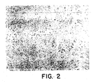
- tungsten carbide (WC) powder was mixed in a ratio of 94.5% WC/5.5% Co, mixed with a lubricant, and pressed into a shape.
- the shape was surrounded with Al2O3 grains mixed with 2.5% BN powder by weight, placed in a graphite boat, and both pre-sintered and sintered in a continuous stoking furnace.
- a sintering temperature of 1410°C was maintained for about 70 minutes. During sintering, disassociated ammonia gas (nitrogen and hydrogen) flowed through the furnace.
- the resulting microstructure (prepared and etched with the acid etch as described earlier) is shown in Figure 2.
- Figure 2 When comparing the treated microstructure in Figure 2 with the microstructure in Figure 1, which was prepared in the same way except that no boron nitride was in the sintering sand, it will be noted that the sample which was treated with boron exhibits an unusual feathery or lacy etched constituent. The etched constituent is distributed fairly homogeneously throughout the sample. The tips of the feathers or branches appear darker and thicker than the rest of the etched constituent. Analyses which will be described later indicate that some form of boron is present in the feathery structure.
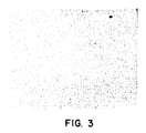
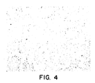
- a sample of a medium grain WC powder was mixed in a ratio of 87% WC/13% Co, mixed with a lubricant, pressed into a shape, and, as in Example 2, sintered in a sand containing 2.5% by weight BN.
- the sample was polished and etched with an acid etchant as described earlier, and its microstructure is shown in Figure 4. Again, when comparing the microstructure of Figure 4 with the microstructure of the same material sintered without BN, shown in Figure 3, the microstructure of Figure 4 exhibits the branching etched constituent. Again, the tips of the branches are thicker and darker than the rest.
- a medium grain sample of 87% WC/13% Co was prepared as in Example 1 except that 0.5% by weight of BN was added to the sand. Again, the branching effect is seen, and, upon greater magnification, white spots appear as indicated by the arrows.
- the bodies were held at a sintering temperature of 1410°C for sixty minutes, then cooled.
- the Rockwell hardness (A scale) of the samples was 90.7, and the coercive force Hc was 80.
- the saw tip bodies were prepared as in Example 5 (91% WC/9% Co medium grain) except that the painted bodies were pre-sintered and sintered in a continuous stoking furnace.
- the coated samples were dried under vacuum, then surrounded by alumina (Al2O3) with no boron mixed in the sand and placed on graphite boats.
- a sintering temperature of 1410°C was held for about 70 minutes, during which time disassociated ammonia flowed through the furnace.
- the resulting saw tips were brazed onto 10" (25.4 cm), 40 tooth saw blades.
- the brazed joint strength was tested with a drop weight impact test and compared with brazed joints utilizing standard WC tips.
- the drop-weight impact test results for the boron-treated tips were 1265 metre-grams (166 inch-ounces) versus 1036 metre-grams (136 inch-ounces) for the regular WC tips, an improvement of 22%.
- WC/Co bodies were sintered in alumina sand in a continuous stoking furnace with a sintering temperature of 1410°C maintained for about 70 minutes.
- Samples were made up of various WC/Co grades from micrograin size with 6% Co to medium grain with 13% Co to extra-coarse grade with 6.5% Co.
- the amount of BN in the alumina sand varied from 0% to 2.5% at 0.5% increments for each sample.
- the specific gravity, Rockwell hardness, transverse rupture strength, coercive force, shrink factor and percent weight loss were tested for each sample, and the test results showed that the amount of boron nitride in the sand did not affect those properties to a degree greater than the variation in normal manufacturing.
- the characteristic feathery constituent appeared in the microstructure of each sample in which BN was present in the sand.
- Carbide test plugs having the dimensions of 5.8 mm X 6.3 mm X 19.0 mm (0.2 inches X 0.25 inches X 0.75 inches) were sintered from a medium grain powder of 91% WC/9% Co in alumina sand without any boron present. Subsequently, these test plugs were re-sintered in alumina sand mixed with different types of boron containing powder in a continuous stoking tube furnace at 1410°C for about 70 minutes in an atmosphere of disassociated ammonia. In each case, the microstructure showed the same distinct etching pattern indicating the diffusion of boron into the carbide structure.
- carbide formers such as, the IVB, VB and VIB elements, for example: titanium, zirconium, hafnium, vanadium, niobium, tantalum, chromium, molybdenum, and tungsten, and combinations thereof.
- Binder metals might be manganese, iron, cobalt, nickel, copper, aluminum, silicon, ruthenium, osmium used alone, in combination with each other, or in combination with each other and with any of the IVB, VB and VIB elements listed earlier as carbide formers.
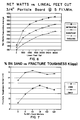
- Fracture toughness and Eddy Current tests were conducted on various types of samples made in accordance with the present invention.
- the first group of samples was made with Vermont American's grade 2M12, a coarse grain 89.5% WC/ 10.5% Co. Varying amounts of boron nitride were mixed in the alumina.
- the second group of samples was made with Vermont American's grade OM2, a fine grain 94% WC/ 6% Co. Varying amounts of boron nitride were mixed in the alumina sand.
- the sintering was done in a disassociated ammonia atmosphere in a continuous stoking furnace with the sintering temperature of 1410°C held for about 70 minutes.
- Figure 7 shows a plot of apparent fracture toughness (Ka) versus percentage by weight of boron nitride in the alumina sand.
- the apparent Fracture Toughness (Ka) shows significant improvement for each alloy upon the addition of BN to the sand. It appears that percent by weight of BN in the sand of between 0.5 and 2 gives optimum fracture toughness. This translates to an amount of boron in the sand of 0.2 to 0.9 percent by weight.
- Figures 8 and 9 are plots of Eddy current results for the same samples.
- the peak for the OM2 grade is at 1.5% BN in the sand for both fracture toughness and Eddy Current, and the 2M12 grade peaks at 1.0%BN in the sand for both tests. These appear to be the optimum BN dopings.
- the standard blade lasted 40 hours.
- the blade with re-sintered tips treated according to the present invention lasted 462 hours and was still cutting well when it was removed for evaluation.
- the samples were OM1 grade containing 91% WC and 9% Co. They were sintered in a continuous stoking furnace in a sand containing 1% BN, and were sintered at 1400°c for one hour. After sintering, a bulk analysis was done to determine the amount of boron in the sample. It was found that an ammonia atmosphere permitted much more boron to enter the microstructure than did a nitrogen atmosphere and that a pure hydrogen atmosphere permitted even more boron to enter the microstructure. In the case of an atmosphere of N2 or dry N2, the sintered sample contained about 30 parts per million (ppm) of boron. In the NH3 atmosphere, the sample contained about 430 ppm boron, and the dry NH3 atmosphere produced a sample having 365 ppm boron. The pure dry hydrogen produced a sample having 1376 ppm boron.
Landscapes
- Chemical & Material Sciences (AREA)
- Organic Chemistry (AREA)
- Engineering & Computer Science (AREA)
- Materials Engineering (AREA)
- Mechanical Engineering (AREA)
- Metallurgy (AREA)
- Dispersion Chemistry (AREA)
- Ceramic Products (AREA)
- Powder Metallurgy (AREA)
- Manufacture Of Alloys Or Alloy Compounds (AREA)
- Glass Compositions (AREA)
- Pharmaceuticals Containing Other Organic And Inorganic Compounds (AREA)
- Carbon And Carbon Compounds (AREA)
Claims (29)
- Verfestigter Carbidkörper, umfassend
eine Wolframcarbidphase;
eine Kobalt-Binderphase; und
eine quarternäre dritte Phase, enthaltend Kobalt, Wolfram, Bor und Kohlenstoff, wobei die dritte Phase durchgehend im Körper verteilt ist. - Verfestigter Carbidkörper nach Anspruch 1, worin in der dritten Phase das Gewichtsverhältnis von Wolfram zu Kobalt größer ist als 1,0:1,0.
- Verfestigter Carbidkörper nach Anspruch 1 oder 2, worin in der dritten Phase das Gewichtsverhältnis von Bor zu Kohlenstoff größer ist als 1,0:1,0.
- Verfestigter Carbidkörper nach Anspruch 3, worin in der dritten Phase das Gewichtsverhältnis von Bor zu Kohlenstoff zwischen 1,0:1,0 und 12,0:1,0 ist.
- Verfestigter Carbidkörper nach irgendeinem vorhergehenden Anspruch, worin die Wolframcarbid-Partikel im allgemeinen winkelig- und blockförmig sind, aber im Bereich der dritten Phase gerundet und kleiner.
- Verfestigter Carbidkörper nach irgendeinem vorhergehenden Anspruch, worin die Durchschnittsgrößen der dritten Phase größer sind als die Durchschnittsgrößen der Kobalt-Binderphase.
- Verfahren zur Herstellung eines verfestigten Carbidkörpers mit einer Wolframcarbidphase, einer Kobalt-Binderphase und einer quarternären dritten Phase mit Kobalt, Wolfram, Bor und Kohlenstoff, das die Verfahrensschritte aufweist:a) Bereitstellen von ein oder mehreren Wolframcarbidkörpern, enthaltend ein Wolframcarbidmaterial und ein Kobalt-Bindermaterial, in einer Form; undb) Sintern der Form in Gegenwart von borhaltigem Material unter Umgeben von mindestens einigen der Wolframcarbidkörper mit borhaltigem Material, so daß merkliche Mengen Bor aus dem borhaltigen Material in die Form übergehen und sich in der Mikrostruktur der Form bis in eine Tiefe von mindestens 3,175 mm (0,125 Inch) oder über die ganze Form, falls die Form weniger als 3,175 mm (0,125 Inch) dick ist, durchgehend verteilen unter Bildung der quarternären dritten Phase, wobei nach dem Sintern die Mikrostruktur der Form, wird sie mit einem sauren Standard-Ätzmittel oder Murakamis Reagens geätzt, im Körper durchgehend eine gefederte Ätzphase zeigt.
- Verfahren nach Anspruch 7, wobei das Sintern unter einer disassoziierten Ammoniak-Atmosphäre erfolgt.
- Verfahren nach Anspruch 7, wobei das Sintern unter einer Wasserstoffatmosphäre erfolgt.
- Verfahren nach Anspruch 7, 8 oder 9, wobei das beim Sintern vorliegende borhaltige Material ausgewählt ist aus Borpulver, Bornitrid, Boroxid, Borcarbid, AlB₂, AlB₁₂, CrB, CrB₂, Cr₃B₅, MoB, NbB₆, NbB₂, B₃Si, B₄Si, B₆Si, TaB, TaB₂, TiB₂, WB, W₂B₅, W₂B, VB₂ und ZrB₂.
- Verfahren nach Anspruch 7, 8 oder 9, wobei beim Sintern die Form in einen Sintersand getaucht wird, der eine Mischung ist mit borhaltigem Material, ausgewählt aus Bornitrid, Bor, Boroxid und Borcarbid.
- Verfahren nach Anspruch 7, 8 oder 9, wobei beim Sintern die Form in Sintersand getaucht wird, der eine Mischung ist mit borhaltigem Material und worin das Bor 0,003 bis 50 Gew.% der Sandmischung stellt.
- Verfahren nach Anspruch 7, 8 oder 9, wobei die Form in ein Sintermedium getaucht wird, das 0,003 bis 50 Gew.% Bor in Form von borhaltigem Material, ausgewählt aus BN, Bor, Boroxid und Borcarbid, enthält.
- Verfahren nach Anspruch 7, 8 oder 9, wobei beim Sintern die Form in eine Mischung aus Sintersand und Bornitrid, das in einer Menge von 0,05 bis 2 Gew.% der Mischung vorliegt, getaucht wird.
- Verfahren nach einem der Ansprüche 7 bis 14, wobei die Form zuvor gesintert wurde und der Vorgang nunmehr ein erneutes Sintern des zuvor gesinterten Körpers ist.
- Verfahren nach Anspruch 7, 8 oder 9, wobei die Form vor dem Sintern mit einem borhaltigen Anstrich versehen wird.
- Verfahren nach Anspruch 7, 8 oder 9, wobei die Form in Kontakt mit einer Oberfläche gebracht wird, die vor dem Sintern mit einem borhaltigen Material beschichtet wurde.
- Verfahren zur Herstellung eines verfestigten Carbidkörpers mit einer Wolframcarbidphase, einer Kobalt-Binderphase und einer quarternären dritten Phase mit Kobalt, Wolfram, Bor und Kohlenstoff, wobei das Verfahren die Schritte aufweist:
Bereitstellen von ein oder mehreren Wolframcarbidkörpern, enthaltend ein Wolframcarbidmaterial und eine Kobalt-Bindermaterial, in einer Form;
Tauchen der Form in einen Sintersand, der eine Mischung ist mit einer kontrollierten Menge eines borhaltigen Materials; und
Sintern der Form in einer Sandmischung unter kontrollierten Bedingungen unter Umgeben von mindestens einigen der Wolframcarbidkörper mit borhaltigem Material, wobei in der Form durchgehend ein Gradient hergestellt wird mit irgendeiner Form von Bor - wobei die Menge an Bor an der Außenseite höher ist und deren Konzentration zur Mitte hin allmählich abnimmt - so daß eine quarternäre dritte Phase geschaffen wird, in der nach dem Sintern die Mikrostruktur der Form, erfolgt ein Ätzen mit einem sauren Standard-Ätzmittel oder Murakamis Reagens, im Körper durchgehend eine federartige Ätzform zeigt. - Verfestigter Carbidkörper, umfassenda) eine Carbidphase, enthaltend einen Carbidbildner und Kohlenstoff;b) eine Binderphase, die hauptsächlich aus einem Binderelement hergestellt ist; undc) eine quarternäre dritte Phase, die im Körper durchgehend eine Dispersion von borhaltigem Material enthält, wobei die Mikrostruktur des Carbidkörpers, erfolgt ein Ätzen mit Murakamis Reagens oder einer Säurelösung, im Körper durchgehend eine Ätzphase mit gefederter Struktur zeigt.
- Verfestigter Carbidkörper nach Anspruch 19, worina) der Carbidbildner ausgewählt ist aus Titan, Zircon, Hafnium, Vanadium, Niob, Tantal, Chrom, Molybdän und Wolfram;b) die Binderphase ausgewählt ist aus Mangan, Eisen, Kobalt, Nickel, Kupfer, Aluminium, Silicium, Ruthenium und Osmium; undc) die Menge an Bor im Körper 25 bis 3000 ppm ist.
- Verfestigter Carbidkörper nach Anspruch 19, worin die Carbidphase WC ist und die Binderphase Kobalt.
- Verfestigter Carbidkörper nach irgendeinem der Ansprüche 1 bis 16, 19 und 21, worin die Menge an Bor im Körper 25 bis 3000 ppm ist.
- Verfestigter Carbidkörper nach irgendeinem der Ansprüche 19 bis 22, worin die Verteilung der Menge an Bor im Körper ein gesteuerter Gradient ist, wobei die Borkonzentration in der Ätzphase an der Oberfläche höher ist und zur Mitte des Körpers hin abnimmt.
- Verfestigter Carbidkörper nach irgendeinem Anspruch 19 bis 23, worin die Ätzphase auch einen höheren Gewichtsprozentsatz Carbidbildner enthält als die Binderphase.
- Verfestigter Carbidkörper, umfassenda) eine Carbidphase, enthaltend einen Carbidbildner und Kohlenstoff;b) eine Binderphase mit weniger als 30 Gew.% Carbidbildner; undc) eine quarternäre dritte Phase, enthaltend ein Bindermaterial und Bor,worin die dritte Phase im Körper durchgehend eine Dispersion von borhaltigem Material enthält, wobei die Mikrostruktur des Carbidkörpers, wird sie mit Murakamis Reagens oder einer Säurelösung geätzt, im Körper durchgehend eine Ätzphase einer federartiger Struktur zeigt.
- Verfestigter Carbidkörper nach Anspruch 25, worin die dritte Phase auch mindestens 40 Gew.% Carbidbildner enthält.
- Verfestigter Carbidkörper nach Anspruch 25 oder 26, worin der Carbidbildner Wolfram ist und die dritte Phase ca. 60 Gew.% Wolfram enthält.
- Verfestigter Carbidkörper nach Anspruch 19, worin vor dem Ätzen die Ätzphase etwas von dem Carbidbildner, etwas von dem Binderelement, etwas Kohlenstoff und etwas Bor enthält und worin in der Ätzphase das Gewichtsverhältnis von Carbidbildner zu Binderelement größer ist als 1,0:1,0.
- Verfestigter Carbidkörper nach irgendeinem der Ansprüche 1 bis 6, worin das Bor in der dritten Phase herkommt von Borpulver, Bornitrid, Boroxid, Borcarbid, AlB₂, AlB₁₂, CrB, CrB₂, Cr₃B₅, MoB, NbB₆, NbB₂, B₃Si, B₄Si, B₆Si, TaB, TaB₂, TiB₂, WB, W₂B₅, W₂B, VB₂ und ZrB₂.
Applications Claiming Priority (6)
| Application Number | Priority Date | Filing Date | Title |
|---|---|---|---|
| US16700088A | 1988-03-11 | 1988-03-11 | |
| US167000 | 1988-03-11 | ||
| US21119788A | 1988-06-29 | 1988-06-29 | |
| US211197 | 1988-06-29 | ||
| US07/317,612 US4961780A (en) | 1988-06-29 | 1989-03-06 | Boron-treated hard metal |
| US317612 | 1989-03-06 |
Publications (2)
| Publication Number | Publication Date |
|---|---|
| EP0332463A1 EP0332463A1 (de) | 1989-09-13 |
| EP0332463B1 true EP0332463B1 (de) | 1994-07-27 |
Family
ID=27389335
Family Applications (1)
| Application Number | Title | Priority Date | Filing Date |
|---|---|---|---|
| EP89302400A Expired - Lifetime EP0332463B1 (de) | 1988-03-11 | 1989-03-10 | Borbehandeltes Hartmetall |
Country Status (11)
| Country | Link |
|---|---|
| EP (1) | EP0332463B1 (de) |
| JP (1) | JP2766661B2 (de) |
| KR (1) | KR890014773A (de) |
| CN (1) | CN1039837C (de) |
| AT (1) | ATE109123T1 (de) |
| BR (1) | BR8901168A (de) |
| CA (1) | CA1334434C (de) |
| DE (1) | DE68916987T2 (de) |
| DK (1) | DK118489A (de) |
| ES (1) | ES2060754T3 (de) |
| RU (1) | RU2046152C1 (de) |
Families Citing this family (15)
| Publication number | Priority date | Publication date | Assignee | Title |
|---|---|---|---|---|
| JPH05271842A (ja) * | 1990-09-12 | 1993-10-19 | Hitachi Metals Ltd | サーメット合金及びその製造方法 |
| GB2263704B (en) * | 1992-01-29 | 1995-08-30 | Toyo Kohan Co Ltd | Heat-resistant sintered hard alloy |
| US5623723A (en) * | 1995-08-11 | 1997-04-22 | Greenfield; Mark S. | Hard composite and method of making the same |
| KR100514342B1 (ko) * | 1998-03-25 | 2005-12-05 | 두산인프라코어 주식회사 | 초경합금 |
| GB2429980A (en) * | 2005-09-08 | 2007-03-14 | John James Saveker | Material comprising a carbide, boride or oxide and tungsten carbide |
| JP2009200179A (ja) * | 2008-02-20 | 2009-09-03 | Ulvac Japan Ltd | 焼結体の製造方法 |
| CN101701311B (zh) * | 2009-09-29 | 2011-03-09 | 武汉科技大学 | 一种WCoB三元硼化物金属陶瓷材料及其制备方法 |
| CN103060651B (zh) * | 2012-12-28 | 2015-03-04 | 鞍山煜宸科技有限公司 | 球铁轧辊表面激光强化用纳米陶瓷合金材料及其制备方法 |
| CN103769576A (zh) * | 2014-01-08 | 2014-05-07 | 北矿新材科技有限公司 | 一种用于制备低孔隙率涂层的碳化钨基耐磨涂层材料及其制备方法 |
| CN104073665B (zh) * | 2014-06-26 | 2016-05-11 | 东北大学 | 一种WC-Co-cBN复合材料的制备方法 |
| CN104354345B (zh) * | 2014-11-28 | 2016-08-03 | 厦门钨业股份有限公司 | 一种具有壳层结构的含硼梯度硬质合金及其制备方法 |
| DE102015203389A1 (de) * | 2015-02-25 | 2016-08-25 | Aktiebolaget Skf | Bohrmotor-Lageranordnung |
| CN106319316A (zh) * | 2016-10-09 | 2017-01-11 | 张倩楠 | 一种硬质合金及其制造方法 |
| US11976011B2 (en) * | 2018-10-30 | 2024-05-07 | Hyperion Materials & Technologies, Inc. | Methods of boronizing sintered bodies and tools for cold forming operations and hollow wear parts with boronized sintered bodies |
| CA3190298A1 (en) * | 2020-11-05 | 2022-05-12 | Andrew Gledhill | Cemented tungsten carbide body and method of forming the cemented tungsten carbide body |
Family Cites Families (2)
| Publication number | Priority date | Publication date | Assignee | Title |
|---|---|---|---|---|
| EP0062311B1 (de) * | 1981-04-06 | 1985-07-17 | Mitsubishi Materials Corporation | Verschleissfeste Legierung auf Wolframkarbidbasis für Warmbearbeitungswerkzeuge |
| DE3574738D1 (de) * | 1984-11-13 | 1990-01-18 | Santrade Ltd | Gesinterte hartmetallegierung zum gesteinsbohren und zum schneiden von mineralien. |
-
1989
- 1989-03-10 DE DE68916987T patent/DE68916987T2/de not_active Expired - Fee Related
- 1989-03-10 DK DK118489A patent/DK118489A/da not_active Application Discontinuation
- 1989-03-10 AT AT89302400T patent/ATE109123T1/de not_active IP Right Cessation
- 1989-03-10 ES ES89302400T patent/ES2060754T3/es not_active Expired - Lifetime
- 1989-03-10 EP EP89302400A patent/EP0332463B1/de not_active Expired - Lifetime
- 1989-03-11 CN CN89102581A patent/CN1039837C/zh not_active Expired - Lifetime
- 1989-03-11 KR KR1019890003064A patent/KR890014773A/ko not_active Ceased
- 1989-03-11 RU SU894613650A patent/RU2046152C1/ru active
- 1989-03-13 JP JP1060596A patent/JP2766661B2/ja not_active Expired - Fee Related
- 1989-03-13 BR BR898901168A patent/BR8901168A/pt not_active IP Right Cessation
- 1989-03-13 CA CA000593448A patent/CA1334434C/en not_active Expired - Lifetime
Also Published As
| Publication number | Publication date |
|---|---|
| CN1037930A (zh) | 1989-12-13 |
| ES2060754T3 (es) | 1994-12-01 |
| ATE109123T1 (de) | 1994-08-15 |
| EP0332463A1 (de) | 1989-09-13 |
| BR8901168A (pt) | 1989-10-31 |
| DK118489A (da) | 1989-09-12 |
| JPH0285333A (ja) | 1990-03-26 |
| CN1039837C (zh) | 1998-09-16 |
| DE68916987D1 (de) | 1994-09-01 |
| JP2766661B2 (ja) | 1998-06-18 |
| DE68916987T2 (de) | 1994-12-01 |
| CA1334434C (en) | 1995-02-14 |
| RU2046152C1 (ru) | 1995-10-20 |
| KR890014773A (ko) | 1989-10-25 |
| DK118489D0 (da) | 1989-03-10 |
Similar Documents
| Publication | Publication Date | Title |
|---|---|---|
| EP0332463B1 (de) | Borbehandeltes Hartmetall | |
| US5116416A (en) | Boron-treated hard metal | |
| EP0586683B1 (de) | Mit mehreren metallschichten umhüllte diamantschleifmittel mit einer stromlos abgeschiedener metallschicht | |
| US5250086A (en) | Multi-layer metal coated diamond abrasives for sintered metal bonded tools | |
| JP6703757B2 (ja) | サーメット、及び切削工具 | |
| EP1922429B1 (de) | Feinkörniges polykristallines schleifmaterial | |
| EP0251264B1 (de) | Diamant-beschichtetes gesintertes Hartmetallmaterial auf der Basis von Wolframcarbid, geeignet als Schneidwerkzeugeinsatz | |
| US4961780A (en) | Boron-treated hard metal | |
| EP0559901A1 (de) | Hartlegierung und deren herstellung | |
| EP0344421B1 (de) | Gesinterte, oberflächenveredelte Legierung mit und ohne Hartbeschichtung sowie Verfahren zur Herstellung der Legierung | |
| JP2009024214A (ja) | 超硬合金およびその製造方法 | |
| JP2025106304A (ja) | 焼結多結晶立方晶窒化ホウ素材料 | |
| DE69425459T2 (de) | Substrat auf Keramikbasis und Verfahren zu dessen Herstellung | |
| JPS6159391B2 (de) | ||
| KR100452173B1 (ko) | 공구용 질화규소 소결체 및 이의 제조방법 | |
| JPH0568548B2 (de) | ||
| KR101640644B1 (ko) | 내열충격성이 향상된 Ti계 소결합금 및 이를 이용한 절삭공구 | |
| JP4540791B2 (ja) | 切削工具用サーメット | |
| JP2511694B2 (ja) | 表面調質焼結合金及びその製造方法並びにその合金に硬質膜を被覆してなる被覆表面調質焼結合金 | |
| JP2814452B2 (ja) | 表面調質焼結合金及びその製造方法並びにその合金に硬質膜を被覆してなる被覆表面調質焼結合金 | |
| JPS6242988B2 (de) | ||
| JPS6050905A (ja) | 薄膜磁気ヘッド用セラミックス基板 | |
| KR830000707B1 (ko) | 초경 합금 | |
| JPH0617229A (ja) | 表面被覆サーメット製切削工具 | |
| WO2016114190A1 (ja) | サーメット、切削工具、及びサーメットの製造方法 |
Legal Events
| Date | Code | Title | Description |
|---|---|---|---|
| PUAI | Public reference made under article 153(3) epc to a published international application that has entered the european phase |
Free format text: ORIGINAL CODE: 0009012 |
|
| AK | Designated contracting states |
Kind code of ref document: A1 Designated state(s): AT BE CH DE ES FR GB GR IT LI LU NL SE |
|
| 17P | Request for examination filed |
Effective date: 19900215 |
|
| 17Q | First examination report despatched |
Effective date: 19920706 |
|
| GRAA | (expected) grant |
Free format text: ORIGINAL CODE: 0009210 |
|
| AK | Designated contracting states |
Kind code of ref document: B1 Designated state(s): AT BE CH DE ES FR GB GR IT LI LU NL SE |
|
| PG25 | Lapsed in a contracting state [announced via postgrant information from national office to epo] |
Ref country code: GR Free format text: LAPSE BECAUSE OF FAILURE TO SUBMIT A TRANSLATION OF THE DESCRIPTION OR TO PAY THE FEE WITHIN THE PRESCRIBED TIME-LIMIT Effective date: 19940727 |
|
| REF | Corresponds to: |
Ref document number: 109123 Country of ref document: AT Date of ref document: 19940815 Kind code of ref document: T |
|
| REF | Corresponds to: |
Ref document number: 68916987 Country of ref document: DE Date of ref document: 19940901 |
|
| ET | Fr: translation filed | ||
| REG | Reference to a national code |
Ref country code: GB Ref legal event code: 727 |
|
| ITF | It: translation for a ep patent filed | ||
| REG | Reference to a national code |
Ref country code: ES Ref legal event code: FG2A Ref document number: 2060754 Country of ref document: ES Kind code of ref document: T3 |
|
| K2C2 | Correction of patent specification (partial reprint) published |
Effective date: 19940727 |
|
| EAL | Se: european patent in force in sweden |
Ref document number: 89302400.0 |
|
| NLR4 | Nl: receipt of corrected translation in the netherlands language at the initiative of the proprietor of the patent | ||
| PLBE | No opposition filed within time limit |
Free format text: ORIGINAL CODE: 0009261 |
|
| STAA | Information on the status of an ep patent application or granted ep patent |
Free format text: STATUS: NO OPPOSITION FILED WITHIN TIME LIMIT |
|
| 26N | No opposition filed | ||
| REG | Reference to a national code |
Ref country code: GB Ref legal event code: 711H |
|
| REG | Reference to a national code |
Ref country code: GB Ref legal event code: IF02 |
|
| PGFP | Annual fee paid to national office [announced via postgrant information from national office to epo] |
Ref country code: LU Payment date: 20040323 Year of fee payment: 16 |
|
| PG25 | Lapsed in a contracting state [announced via postgrant information from national office to epo] |
Ref country code: LU Free format text: LAPSE BECAUSE OF NON-PAYMENT OF DUE FEES Effective date: 20050310 |
|
| PGFP | Annual fee paid to national office [announced via postgrant information from national office to epo] |
Ref country code: FR Payment date: 20050318 Year of fee payment: 17 |
|
| PGFP | Annual fee paid to national office [announced via postgrant information from national office to epo] |
Ref country code: AT Payment date: 20050322 Year of fee payment: 17 Ref country code: BE Payment date: 20050322 Year of fee payment: 17 |
|
| PGFP | Annual fee paid to national office [announced via postgrant information from national office to epo] |
Ref country code: SE Payment date: 20050323 Year of fee payment: 17 Ref country code: CH Payment date: 20050323 Year of fee payment: 17 |
|
| PGFP | Annual fee paid to national office [announced via postgrant information from national office to epo] |
Ref country code: ES Payment date: 20050413 Year of fee payment: 17 |
|
| PGFP | Annual fee paid to national office [announced via postgrant information from national office to epo] |
Ref country code: DE Payment date: 20050513 Year of fee payment: 17 |
|
| PG25 | Lapsed in a contracting state [announced via postgrant information from national office to epo] |
Ref country code: AT Free format text: LAPSE BECAUSE OF NON-PAYMENT OF DUE FEES Effective date: 20060310 |
|
| PG25 | Lapsed in a contracting state [announced via postgrant information from national office to epo] |
Ref country code: ES Free format text: LAPSE BECAUSE OF NON-PAYMENT OF DUE FEES Effective date: 20060311 Ref country code: SE Free format text: LAPSE BECAUSE OF NON-PAYMENT OF DUE FEES Effective date: 20060311 |
|
| PG25 | Lapsed in a contracting state [announced via postgrant information from national office to epo] |
Ref country code: CH Free format text: LAPSE BECAUSE OF NON-PAYMENT OF DUE FEES Effective date: 20060331 Ref country code: BE Free format text: LAPSE BECAUSE OF NON-PAYMENT OF DUE FEES Effective date: 20060331 Ref country code: LI Free format text: LAPSE BECAUSE OF NON-PAYMENT OF DUE FEES Effective date: 20060331 |
|
| PGFP | Annual fee paid to national office [announced via postgrant information from national office to epo] |
Ref country code: IT Payment date: 20060331 Year of fee payment: 18 |
|
| PG25 | Lapsed in a contracting state [announced via postgrant information from national office to epo] |
Ref country code: DE Free format text: LAPSE BECAUSE OF NON-PAYMENT OF DUE FEES Effective date: 20061003 |
|
| REG | Reference to a national code |
Ref country code: CH Ref legal event code: PL |
|
| EUG | Se: european patent has lapsed | ||
| REG | Reference to a national code |
Ref country code: FR Ref legal event code: ST Effective date: 20061130 |
|
| REG | Reference to a national code |
Ref country code: ES Ref legal event code: FD2A Effective date: 20060311 |
|
| BERE | Be: lapsed |
Owner name: *VERMONT AMERICAN CORP. Effective date: 20060331 |
|
| PG25 | Lapsed in a contracting state [announced via postgrant information from national office to epo] |
Ref country code: FR Free format text: LAPSE BECAUSE OF NON-PAYMENT OF DUE FEES Effective date: 20060331 |
|
| PGFP | Annual fee paid to national office [announced via postgrant information from national office to epo] |
Ref country code: GB Payment date: 20080318 Year of fee payment: 20 |
|
| PGFP | Annual fee paid to national office [announced via postgrant information from national office to epo] |
Ref country code: NL Payment date: 20080318 Year of fee payment: 20 |
|
| REG | Reference to a national code |
Ref country code: GB Ref legal event code: PE20 Expiry date: 20090309 |
|
| NLV7 | Nl: ceased due to reaching the maximum lifetime of a patent |
Effective date: 20090310 |
|
| PG25 | Lapsed in a contracting state [announced via postgrant information from national office to epo] |
Ref country code: NL Free format text: LAPSE BECAUSE OF EXPIRATION OF PROTECTION Effective date: 20090310 |
|
| PG25 | Lapsed in a contracting state [announced via postgrant information from national office to epo] |
Ref country code: GB Free format text: LAPSE BECAUSE OF EXPIRATION OF PROTECTION Effective date: 20090309 |
|
| PG25 | Lapsed in a contracting state [announced via postgrant information from national office to epo] |
Ref country code: IT Free format text: LAPSE BECAUSE OF NON-PAYMENT OF DUE FEES Effective date: 20070310 |