EP0332399A1 - Hydraulisches Blockierschutzbremssystem für Fahrzeuge - Google Patents
Hydraulisches Blockierschutzbremssystem für Fahrzeuge Download PDFInfo
- Publication number
- EP0332399A1 EP0332399A1 EP89302262A EP89302262A EP0332399A1 EP 0332399 A1 EP0332399 A1 EP 0332399A1 EP 89302262 A EP89302262 A EP 89302262A EP 89302262 A EP89302262 A EP 89302262A EP 0332399 A1 EP0332399 A1 EP 0332399A1
- Authority
- EP
- European Patent Office
- Prior art keywords
- valve
- brake
- master cylinder
- flow
- pump
- Prior art date
- Legal status (The legal status is an assumption and is not a legal conclusion. Google has not performed a legal analysis and makes no representation as to the accuracy of the status listed.)
- Granted
Links
Images


Classifications
-
- B—PERFORMING OPERATIONS; TRANSPORTING
- B60—VEHICLES IN GENERAL
- B60T—VEHICLE BRAKE CONTROL SYSTEMS OR PARTS THEREOF; BRAKE CONTROL SYSTEMS OR PARTS THEREOF, IN GENERAL; ARRANGEMENT OF BRAKING ELEMENTS ON VEHICLES IN GENERAL; PORTABLE DEVICES FOR PREVENTING UNWANTED MOVEMENT OF VEHICLES; VEHICLE MODIFICATIONS TO FACILITATE COOLING OF BRAKES
- B60T8/00—Arrangements for adjusting wheel-braking force to meet varying vehicular or ground-surface conditions, e.g. limiting or varying distribution of braking force
- B60T8/32—Arrangements for adjusting wheel-braking force to meet varying vehicular or ground-surface conditions, e.g. limiting or varying distribution of braking force responsive to a speed condition, e.g. acceleration or deceleration
- B60T8/34—Arrangements for adjusting wheel-braking force to meet varying vehicular or ground-surface conditions, e.g. limiting or varying distribution of braking force responsive to a speed condition, e.g. acceleration or deceleration having a fluid pressure regulator responsive to a speed condition
- B60T8/50—Arrangements for adjusting wheel-braking force to meet varying vehicular or ground-surface conditions, e.g. limiting or varying distribution of braking force responsive to a speed condition, e.g. acceleration or deceleration having a fluid pressure regulator responsive to a speed condition having means for controlling the rate at which pressure is reapplied to or released from the brake
- B60T8/5006—Pressure reapplication by pulsing of valves
-
- B—PERFORMING OPERATIONS; TRANSPORTING
- B60—VEHICLES IN GENERAL
- B60T—VEHICLE BRAKE CONTROL SYSTEMS OR PARTS THEREOF; BRAKE CONTROL SYSTEMS OR PARTS THEREOF, IN GENERAL; ARRANGEMENT OF BRAKING ELEMENTS ON VEHICLES IN GENERAL; PORTABLE DEVICES FOR PREVENTING UNWANTED MOVEMENT OF VEHICLES; VEHICLE MODIFICATIONS TO FACILITATE COOLING OF BRAKES
- B60T8/00—Arrangements for adjusting wheel-braking force to meet varying vehicular or ground-surface conditions, e.g. limiting or varying distribution of braking force
- B60T8/32—Arrangements for adjusting wheel-braking force to meet varying vehicular or ground-surface conditions, e.g. limiting or varying distribution of braking force responsive to a speed condition, e.g. acceleration or deceleration
- B60T8/34—Arrangements for adjusting wheel-braking force to meet varying vehicular or ground-surface conditions, e.g. limiting or varying distribution of braking force responsive to a speed condition, e.g. acceleration or deceleration having a fluid pressure regulator responsive to a speed condition
- B60T8/42—Arrangements for adjusting wheel-braking force to meet varying vehicular or ground-surface conditions, e.g. limiting or varying distribution of braking force responsive to a speed condition, e.g. acceleration or deceleration having a fluid pressure regulator responsive to a speed condition having expanding chambers for controlling pressure, i.e. closed systems
- B60T8/4275—Pump-back systems
- B60T8/4291—Pump-back systems having means to reduce or eliminate pedal kick-back
-
- B—PERFORMING OPERATIONS; TRANSPORTING
- B60—VEHICLES IN GENERAL
- B60T—VEHICLE BRAKE CONTROL SYSTEMS OR PARTS THEREOF; BRAKE CONTROL SYSTEMS OR PARTS THEREOF, IN GENERAL; ARRANGEMENT OF BRAKING ELEMENTS ON VEHICLES IN GENERAL; PORTABLE DEVICES FOR PREVENTING UNWANTED MOVEMENT OF VEHICLES; VEHICLE MODIFICATIONS TO FACILITATE COOLING OF BRAKES
- B60T8/00—Arrangements for adjusting wheel-braking force to meet varying vehicular or ground-surface conditions, e.g. limiting or varying distribution of braking force
- B60T8/32—Arrangements for adjusting wheel-braking force to meet varying vehicular or ground-surface conditions, e.g. limiting or varying distribution of braking force responsive to a speed condition, e.g. acceleration or deceleration
- B60T8/34—Arrangements for adjusting wheel-braking force to meet varying vehicular or ground-surface conditions, e.g. limiting or varying distribution of braking force responsive to a speed condition, e.g. acceleration or deceleration having a fluid pressure regulator responsive to a speed condition
- B60T8/50—Arrangements for adjusting wheel-braking force to meet varying vehicular or ground-surface conditions, e.g. limiting or varying distribution of braking force responsive to a speed condition, e.g. acceleration or deceleration having a fluid pressure regulator responsive to a speed condition having means for controlling the rate at which pressure is reapplied to or released from the brake
- B60T8/5018—Pressure reapplication using restrictions
- B60T8/5025—Pressure reapplication using restrictions in hydraulic brake systems
- B60T8/5037—Pressure reapplication using restrictions in hydraulic brake systems closed systems
Definitions
- This invention relates to hydraulic anti-lock braking systems for vehicles of the kind in which the supply of hydraulic fluid from a supply, suitably a master cylinder, to a brake on a wheel is modulated in an anti-lock mode by a modulator in accordance with the behaviour of the braked wheel, and a pump is adapted to generate the energy necessary to recover fluid after the pressure applied to the brake has first been released to prevent the wheel from locking.
- EP-A-0202845 An anti-lock system of the kind set forth is disclosed in EP-A-0202845.
- the modulator incorporates a single solenoid-operated valve responsive to anti-lock signals, and a flow valve.
- the flow valve permits free flow from the master cylinder to the brake.
- fluid is relieved from the brake to an expansion chamber, and the flow valve is adapted to meter the flow of fluid from the master cylinder to the brake at a controlled rate.
- the pump is operative to return fluid from the expansion chamber back to the master cylinder.
- the flow valve and the pump rate are arranged to produce similar flow rates so that the reaction at the foot is minimal.
- the output characteristic of the pump is cyclic and the flow valve characteristic is constant, the pumped activity is sensed as an reaction or "feel" at the brake pedal, accompanied by noise transmitted back through the bulkhead of the vehicle.
- a restrictor could be fitted between the pump and the flow valve. This would restrict the full pump output itself, and not the difference between the pump output and the flow valve output. In addition, damage to the pump might occur.
- Another solution would be to locate a restrictor between the modulator and the master cylinder and provide a one-way valve to permit full flow from the master cylinder to the brake. To obtain a rapid release of brake pressure, another one-way valve would have to be located between the brake and the master cylinder. Although this solution is technically acceptable, it uses too many parts for it to be acceptable from a commercial standpoint.
- the modulator incorporates a valve responsive to anti-lock signals, a flow valve, and an expansion chamber to which fluid is relieved from the brake in a anti-lock mode
- the flow valve is arranged so that the output from the pump is shared between the brake and the master cylinder, and a restrictor located in parallel with the flow valve is adapted to attenuate the pressure oscillations of the system.
- the modulator comprises a solenoid-operated valve responsive to an anti-lock signal and having a solenoid chamber controlled by the valve, a flow valve, a inlet connection adapted normally to transmit free flow of fluid from the master cylinder to the brake, means for isolating the first inlet connection from the brake in an anti-lock mode, and a second restricted connection connected to the outlet from the pump and to the solenoid chamber by way of the flow valve, an attenuation chamber being defined between the pump, the restricted connection, and the flow valve.
- the flow valve is of the spool type, and the master cylinder has two separate inlets to the flow valve, of which the first is unrestricted and is connected to an annular groove within the flow valve which, in turn, is connected to the brake, and the second is restricted by a restrictor and is connected to one side of the flow valve to feed fluid to the solenoid chamber of the valve responsive to anti-lock signals.
- the flow valve is of the diaphragm pressure-responsive type and the master cylinder has two separate inlets of which the first is unrestricted and is connected to the brake by means of a poppet valve, and the second is restricted by a restrictor and is connected to the solenoid chamber of the valve responsive to anti-lock signals through the flow valve.
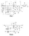
- a brake 1 on a wheel 2 is adapted to be applied by the supply of fluid from a pedal-operated master cylinder 3 through a modulator 4.
- the modulator 4 comprises a first normally-open solenoid-operated valve 5 located in a supply line 6 through which fluid is supplied directly to the brake 1, a second normally-closed solenoid-operated valve 7 controlling a dump line 8 from the brake 1 to an expansion chamber 9, a flow valve 10 located in a line 11 connected between the dump line 8 on the upstream side of the valve 7 and a return line 12 connected between the master cylinder 3 and the valve 5, and a restrictor 13 in the return line.
- a one-way valve 14 is connected in parallel with the valve 5.
- the speed of rotation of the wheel 2 is sensed by a speed sensor 17, the signals from which are fed to a control module 18 which, in turn, is operative to send energising current to the solenoids of the two valves 5 and 7 in accordance with the behaviour of the wheel 2.
- valve 5 Normally the valve 5 is open so that the master cylinder 3 is in open communication with the brake 1, and the valve 7 is closed to isolate the expansion chamber 9 from the brake.
- the pump 15 is inoperative with its motor de-energised or disabled.
- valve 5 closes to isolate the master cylinder 3 from the brake 1, and the valve 7 opens so that fluid from the brake 1 is dumped to the expansion chamber 9.
- the pump 15 is driven to draw fluid from the chamber 9 and pump it to the brake 1 through the flow valve 10 and to the master cylinder 3 through the restrictor 13.
- valve 7 When the wheel recovers the valve 7 closes and the valve 5 opens.
- the fluid withdrawn from the expansion chamber 9 by the pump 15 is pumped back to the brake 1 at a rate determined by flow through the flow valve 10, and back to the master cylinder at a rate determined by flow through the restrictor 13.
- the flow valve 10 and the restrictor 13 automatically define an attenuation system since the flow valve 10 automatically provides an attenuation volume between the pump 15 and the restrictor 13 back to the master cylinder 3.
- the flow valve 10 gives better attenuation than a fixed "high" stiffness volume and has an effect similar, in practice, to that of an hydraulic accumulator. Pressure spikes from the pump 15 will cause the volume upstream of the flow valve 10 to increase, thus reducing its amplitude.
- the attenuation system Since the flow from the pump 15 is split between the master cylinder 3 and the brake 1, the attenuation system only attenuates the flow back to the master cylinder 3.
- the flow valve 10 is positioned in a return to the brake 1.
- the return line to the master cylinder 3 containing the restrictor 13 is connected between the pump 15 and the flow valve 10.
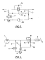
- the anti-lock braking system illustrated in Figure 5 of the drawings comprises a pedal-operated hydraulic master cylinder 21 for operating a wheel brake 22, and a modulator 23.
- the modulator 23 comprises a housing 24 in which is incorporated a solenoid-operated exhaust valve 25, a flow-control regulator valve 26, a pump 28, and an expander chamber 29.
- a wheel speed sensor 30 supplies electrical wheel speed signals to a control module 31.
- the control module 31 analyses the speed signals and when it recognises a critical speed signal it causes an electrical current to energise the solenoid 32 of the exhaust valve 25 and also, separately, to operate an electric motor 33 for driving the pump 28.
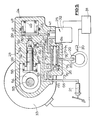
- the solenoid-operated exhaust valve 25 comprises an armature incorporating a valve head 41 which is normally urged into engagement with a seating 43 between a passage 44 leading to the regulator valve 26 and the expander chamber 29, by means of a spring.
- the chamber 29 constitutes a substantially constant, low pressure, reservoir for the pump 28 and is closed at its upper end by an expander piston 47 working in a portion 48 of a bore of stepped outline which portion is of largest diameter.
- Normally a compression spring 49 urges the expander piston 47 into an advanced position in which the effective volume of the expander chamber 29 is at a minimum.
- the pump 28 comprises a plunger 52 which works in the portion 53 of the stepped bore which is of smaller diameter.
- the plunger 52 is driven in one direction during a power stroke by an eccentric cam 54 on a drive shaft 55 from the electric motor 33, and in the opposite direction, during an induction stroke, by a spring 56.
- a pumping chamber 59 at the outer end of the stepped bore through a one-way inlet valve 60
- a restrictor 63 is located in the passage 61.
- the passage 61 joins a passage 65 from the master cylinder at a branch 66 which comprises an inlet passage leading to the flow-control regulator valve 26 and located between the master cylinder 21 and the restrictor 63.
- the flow-control regulator valve 26 comprises a spool 70 working in a bore 71.
- the spool 70 is provided at opposite ends of a radial groove 72 with axially spaced lands 73 and 74.
- the spool 70 has a longitudinal bore 75 which terminates at its inner end remote from the exhaust valve 25 in a restricted orifice 76.
- a spring 77 acts normally to urge the spool 70 into a first position in engagement with the adjacent end of the bore 71.
- the first land 73 is located between a first port 80 and second port 81, and the second land 74 closes a third port 82 in communication with the passage 44 and is spaced from a fourth exhaust port 83 so that the port 83 in permanent communication with the passage 44 is also open to a chamber 84 at the inner end of the bore 71 on the downstream side of the orifice 76.
- the groove 72 is always in free communication with an outlet port 85 connected to the brake 22.
- the port 80 is connected to the passage 61 between the restrictor 63 and the valve 62, and the port 81 is connected to the passage 61 between the restrictor 63 and the master cylinder 21.
- the pump 28 In the inoperative position shown the pump 28 is disabled.
- the solenoid 32 is de-energised and the exhaust valve 25 is held in a closed position by the spring acting on the valve head 41.
- the spool 70 is held against the inner end of the bore 71 to permit free and unrestricted communication between the master cylinder 21 and the brake 22 through the port 81, the groove 72 and the port 85.
- the control module 31 When a skid signal is received, the control module 31 is operative to energise the solenoid 32 and the electric motor 33.
- the solenoid 32 withdraws the armature against the force in its spring, in turn urging the valve head 41 away from the seating 43 to open the exhaust valve 25, and energisation of the motor 12 causes the shaft 55 to rotate.
- the consequent pressure drop across the fixed orifice 76 causes the spool 70 to move relatively towards the exhaust valve 25 against the force in the spring 77.
- Initial movement of the spool 70 in this direction causes the land 73 to close the inlet port 81, with which it defines an inlet valve, which isolates the master cylinder 21 from the brake 22.
- Further movement of the spool 70 in the same direction causes the land 74 to uncover the third port 82 in turn to place the ports 82 and 85 in communication through the groove 72 with the result that the brake 22 is also connected to the expander chamber 29 to relieve the pressure applied to the brake 22.
- the spool 70 moves into a rest position at which the land 74 hovers at the edge of the exhaust port 83, with the outer edge 86 of the land 74 constituting a variable orifice with the port 83.
- the pressure returned from the brake 22 to the expander chamber 29 moves the expander piston 47 relatively against the force in the spring 49.
- the pump 28 is operable to draw fluid at low pressure from the expander chamber 29 and into the pumping chamber 59 through the inlet valve 60, and then pump it from the chamber 59 and into the passage 61 through the outlet valve 62 as described above.
- the output from the pump 28 is shared between the master cylinder 21 to which it is returned through the restrictor 63, and the brake 22 under the control of the flow valve 26. Specifically the output from the pump 28, minus the output via the flow control valve 26, is returned to the master cylinder 21.
- both ports 82 and 83 are connected directly to the expander chamber 29 when the valve head 41 is spaced from its seating 43.
- fluid is returned from these ports 82 and 83 at an unrestricted rate. This means that in response to a skid signal the pressure applied to the brake 22 is reduced substantially to a minimum, substantially to zero. Additional work must therefore be done by the pump 28 to re-apply the brake 22, with a consequent time delay.
- the anti-lock braking system illustrated in Figure 6 of the accompanying drawings incorporates a two-rate dump valve 110 which determines the degree to which pressure applied to the brake 22 can be reduced in response to a skid signal.
- the two-rate dump valve 110 comprises a housing 111 having a stepped bore 112 comprising a first bore portion 113 of greatest diameter, a second bore portion 114 of intermediate diameter, and a third bore portion 115 of smallest diameter.
- a valve member 116 housed in the bore 112 comprises a valve head 117 engageable with a seating 118 at the step in diameter between the bore portions 113 and 114, and a stem 120 carrying the head 117 and guided for sliding movement in the bore portion 115 from which it projects at its free end.
- a spring 121 normally urges the head 117 away from the seating 118.
- the port 82 is connected through a passage 122 to a port 123 in the housing 111 which leads into the bore portion 113, and a restricted passage 124 in the valve head 117 provides communication between the bore portions 114 and 113 when the dump valve 110 is closed with the head 117 in engagement with the seating 118.
- the port 83 is permanently connected through a passage 125, and the passage 125 is, itself, placed in communication with the expander chamber 29 when the solenoid-operated exhaust valve 25 opens.
- the system also includes a one-way valve 130 which permits flow from the passage 65 to the flow valve 26, but which prevents return flow in the opposite direction.
- the port 83 is in communication with the port 82 since the dump valve 110 is open with the head 117 held away from the seating 118 by the spring 114.
- valve head 41 When a skid signal is received, the valve head 41 is urged away from the seating 43 to open the exhaust valve 25. This connects the chamber 84 to the expander chamber 29 through the port 83, at the same time placing the dump valve 110 in communication with the expander chamber 29 through the passage 125.
- the consequent pressure drop across the fixed orifice 76 causes the spool 70 to move relatively towards the exhaust valve 25 against the force in the spring 77 until the land 74 hovers at the edge of the exhaust port 83. Any resistance to movement of the spool 70 in this direction and which might otherwise be caused by the restrictor 63, is avoided by the one-way valve 130 opening automatically.
- the flow valve 26 comprises a flexible diaphragm 90 provided with a fixed orifice 91 which establishes a pressure drop across the diaphragm 90. This controls the position of the diaphragm with respect to a seating 92 leading to the valve 25 and with which the diaphragm 90 co-operates in order to define the variable orifice.
- the chamber 93 on the side of the diaphragm 90 remote from the seating 92 is connected to the restrictor 63 and the output valve 62 from the pump 28.
- a poppet valve 94 is located between the master cylinder 21 and the brake 22. As illustrated the poppet valve 94 comprises a spool 95 working in a bore 96 and exposed at one end to pressure on the downstream side of the flow valve 26.
- the spool 95 carries a head 97 which is relatively movable axially and which is normally spaced from a seating 98 between the master cylinder 21 and the brake 22 by the force in a spring 99.
- a light spring 100 is adapted to bias the head 97 in the opposite direction.
- the pump 28 In the inoperative position shown in the drawing the pump 28 is disabled, the solenoid 32 is de-energised, and the head 97 is spaced from the seating 98 so that fluid can be supplied directly from the master cylinder 21 to the brake 22.
- the pressure from the master cylinder 21 is also supplied to the flow valve 26 and the chamber 84 through the restrictor 63.
- the solenoid 32 is energised to retract the valve member 41 momentarily to relieve pressure in the chamber 84 to the expansion chamber 29.
- This causes the spool 95 to move relatively against the force in the spring 99 with the head 97 engaging with the seating 98 to isolate the master cylinder 21 from the brake 22.
- the master cylinder pressure acts through an opening in the head 97 and onto the adjacent end of the spool 95 in turn to urge the spool 95 further in the same direction. This uncovers a port 101 leading both to the flow valve 26 and the chamber 84. The pressure in the brake 22 is therefore relieved to the expansion chamber 29 through the port 101, and the chamber 84.
- the diaphragm 90 moves towards its seating 92 to meter fluid to the brake 22, and the control module 31 switches on the motor 33 to drive the pump 28. Fluid is then forced from the expansion chamber 29 back to the attenuation chamber containing the flow valve 26, and through the restrictor 63 to the master cylinder 21.
- the braking system shown in the layout of Figure 9 is similar to Figure 5. However, in the system of Figure 9 the solenoid-operated exhaust valve 25 is aligned axially with the flow-control regulator valve 26, and the pump 28 and the expander chamber 29 are separate from the housing 24, the pump 28 being driven by an external motor 100.
- the spool 70 controls communication between an inlet port 101 from the master cylinder, and an inner outlet port 102 connected to the brake and disposed axially between the port 101 and the exhaust valve 25.
- a port 103 diametrically opposite and communicating with the port 101 is connected to the pump 28 through the restrictor 63, and the pump 28 has a parallel connection to the flow-regulator valve 26 through a port 104.
- the spool 70 In a normal brake-applying position, the spool 70 is urged relatively away from the exhaust valve 25, which is closed to isolate the brake from the expansion chamber 29, and the groove 72 provides unrestricted communication between the port 101 and the port 102.
- the electric motor 100 When a skid signal is received, the electric motor 100 is energised to drive the pump 28, and the valve 25 opens.
- the groove 72 is omitted and the land 74 is slidably guided in the bore 71.
- the spool 70 is extended in length relatively away from the dump valve 25 to include an addition groove 110, the outer edge 111 of which co-operates with the port 104 to define the metering device which is therefore upstream of the fixed orifice 76.
Applications Claiming Priority (4)
| Application Number | Priority Date | Filing Date | Title |
|---|---|---|---|
| GB888805598A GB8805598D0 (en) | 1988-03-09 | 1988-03-09 | Improvements in hydraulic anti-lock braking systems for vehicles |
| GB8805598 | 1988-03-09 | ||
| GB888817412A GB8817412D0 (en) | 1988-03-09 | 1988-07-21 | Improvements in hydraulic anti-lock braking systems for vehicles |
| GB8817412 | 1988-07-21 |
Publications (2)
| Publication Number | Publication Date |
|---|---|
| EP0332399A1 true EP0332399A1 (de) | 1989-09-13 |
| EP0332399B1 EP0332399B1 (de) | 1993-05-12 |
Family
ID=26293604
Family Applications (2)
| Application Number | Title | Priority Date | Filing Date |
|---|---|---|---|
| EP89302262A Expired - Lifetime EP0332399B1 (de) | 1988-03-09 | 1989-03-07 | Hydraulisches Blockierschutzbremssystem für Fahrzeuge |
| EP89302261A Expired EP0332398B1 (de) | 1988-03-09 | 1989-03-07 | Hydraulisches Blockierschutzbremssystem für Fahrzeuge |
Family Applications After (1)
| Application Number | Title | Priority Date | Filing Date |
|---|---|---|---|
| EP89302261A Expired EP0332398B1 (de) | 1988-03-09 | 1989-03-07 | Hydraulisches Blockierschutzbremssystem für Fahrzeuge |
Country Status (4)
| Country | Link |
|---|---|
| US (2) | US4929037A (de) |
| EP (2) | EP0332399B1 (de) |
| JP (2) | JPH01297350A (de) |
| DE (2) | DE68902555T2 (de) |
Cited By (13)
| Publication number | Priority date | Publication date | Assignee | Title |
|---|---|---|---|---|
| EP0361502A2 (de) * | 1988-09-30 | 1990-04-04 | Sumitomo Electric Industries, Ltd. | Modulator für Blockierschutzbremssystem |
| WO1990015737A1 (de) * | 1989-06-20 | 1990-12-27 | Robert Bosch Gmbh | Vorrichtung zur druckregulierung in einem hydraulischen antiblockiersystem |
| FR2650799A1 (fr) * | 1989-08-09 | 1991-02-15 | Bosch Gmbh Robert | Installation de freinage hydraulique a dispositif antiblocage pour vehicules automobiles |
| EP0417443A1 (de) * | 1989-09-15 | 1991-03-20 | Robert Bosch Gmbh | Vorrichtung zur Vermeidung des Blockierens der Räder eines Fahrzeugs |
| FR2653400A1 (fr) * | 1989-10-23 | 1991-04-26 | Jidosha Kiki Co | Systeme de commande de freinage anti-blocage. |
| DE4111165A1 (de) * | 1991-04-06 | 1992-10-08 | Teves Gmbh Alfred | Bremsanlage mit bremsschlupf- und antriebsschlupfregelung |
| WO1993000240A1 (de) * | 1991-06-29 | 1993-01-07 | Robert Bosch Gmbh | Hydraulische bremsanlage mit blockierschutz- und/oder antriebsschlupfregeleinrichtung, insbesondere für kraftfahrzeuge |
| DE4134445A1 (de) * | 1991-10-18 | 1993-04-22 | Teves Gmbh Alfred | Blockiergeschuetzte hydraulische bremsanlage |
| EP0545338A1 (de) * | 1991-11-30 | 1993-06-09 | Sumitomo Electric Industries, Ltd | Flüssigkeitsdrucksteuersystem für Antiblockierbremsanlagen |
| EP0546729A1 (de) * | 1991-12-11 | 1993-06-16 | Lucas Industries Public Limited Company | Hydraulische Systeme für Fahrzeuge |
| GB2262580A (en) * | 1991-12-20 | 1993-06-23 | Lucas Ind Plc | Hydraulic anti-lock braking systems for vehicles |
| EP0552461A1 (de) * | 1992-01-23 | 1993-07-28 | ITT Automotive Europe GmbH | Blockiergeschützte hydraulische Bremsanlage |
| EP0597642A2 (de) * | 1992-11-12 | 1994-05-18 | Lucas Industries Public Limited Company | Hydraulische Fahrzeugbremsanlagen |
Families Citing this family (16)
| Publication number | Priority date | Publication date | Assignee | Title |
|---|---|---|---|---|
| DE3740516C2 (de) * | 1987-11-30 | 1999-04-15 | Teves Gmbh Alfred | Blockiergeschützte Bremsanlage |
| DE3838571A1 (de) * | 1988-11-14 | 1990-05-17 | Lucas Ind Plc | Blockiergeschuetzte bremsanlage |
| US5102206A (en) * | 1989-06-26 | 1992-04-07 | General Motors Corporation | Anti-lock braking and traction control system |
| DE4016744A1 (de) * | 1990-05-25 | 1991-11-28 | Teves Gmbh Alfred | Bremsdruckregelvorrichtung |
| DE4130729A1 (de) * | 1990-10-16 | 1992-04-23 | Teves Gmbh Alfred | Bremsdruckregelvorrichtung fuer eine hydraulische kraftfahrzeugbremsanlage |
| GB9021232D0 (en) * | 1990-09-28 | 1990-11-14 | Lucas Ind Plc | Improvements in hydraulic anti-lock braking systems for vehicles |
| BR9105911A (pt) * | 1990-09-28 | 1992-11-10 | Lucas Ind Plc | Sistema anti-bioqueio hidraulico para veiculos |
| US5312175A (en) * | 1991-07-03 | 1994-05-17 | Tokico Ltd. | Brake fluid pressure control apparatus |
| DE4126959A1 (de) * | 1991-08-14 | 1993-02-18 | Lucas Ind Plc | Drucksteuervorrichtung fuer eine antiblockier- und/oder antischlupfanlage |
| DE4132930A1 (de) * | 1991-10-04 | 1993-04-08 | Teves Gmbh Alfred | Pumpe |
| DE4244675C2 (de) * | 1991-11-07 | 1998-10-29 | Tokico Ltd | Antiblockiersystem |
| DE4237561C2 (de) * | 1991-11-07 | 1998-06-04 | Tokico Ltd | Antiblockiersystem |
| US5397175A (en) * | 1992-03-06 | 1995-03-14 | Tokico Ltd. | Fluid pressure control apparatus for antiskid brakes |
| JPH06127363A (ja) * | 1992-10-14 | 1994-05-10 | Nippondenso Co Ltd | 車両用ブレーキ液圧制御装置 |
| US5620028A (en) * | 1995-03-20 | 1997-04-15 | General Motors Corporation | Brake Module with integrated accumulator |
| JPH1067311A (ja) * | 1996-08-27 | 1998-03-10 | Aisin Seiki Co Ltd | 車輪ブレーキ液圧制御装置 |
Citations (10)
| Publication number | Priority date | Publication date | Assignee | Title |
|---|---|---|---|---|
| DE2028609A1 (de) * | 1969-06-10 | 1970-12-17 | The Bendix Corp., Southfield, Mich. (V.St.A.) | Hydraulisches Blockierregel-Bremssystem |
| FR2361256A1 (fr) * | 1976-08-13 | 1978-03-10 | Nissan Motor | Unite de commande d'antiderapage pour vehicule automobile |
| DE2703761A1 (de) * | 1976-09-29 | 1978-08-03 | Bosch Gmbh Robert | Hydraulisches system |
| GB2012872A (en) * | 1978-01-19 | 1979-08-01 | Toyota Motor Co Ltd | Anti vibration apparatus for a vehicle brake system |
| GB2161231A (en) * | 1984-07-04 | 1986-01-08 | Lucas Ind Plc | Anti-skid hydraulic braking systems for vehicles |
| GB2163503A (en) * | 1984-08-09 | 1986-02-26 | Nippon Denso Co | Hydraulic pressure control device for use in vehicle anti-skid braking system |
| EP0219951A1 (de) * | 1985-09-05 | 1987-04-29 | LUCAS INDUSTRIES public limited company | Hydraulischer Blockierverhinderer für Kraftfahrzeuge |
| DE3541742A1 (de) * | 1985-11-26 | 1987-05-27 | Bosch Gmbh Robert | Blockierschutzbremsanlage |
| EP0227332A2 (de) * | 1985-12-03 | 1987-07-01 | LUCAS INDUSTRIES public limited company | Blockierverhinderer für Fahrzeuge |
| EP0242132A2 (de) * | 1986-04-12 | 1987-10-21 | LUCAS INDUSTRIES public limited company | Hydraulisches Blockierschutzbremssystem für Fahrzeuge |
Family Cites Families (12)
| Publication number | Priority date | Publication date | Assignee | Title |
|---|---|---|---|---|
| US3877758A (en) * | 1969-10-18 | 1975-04-15 | Aisin Seiki | Process for the control of an antiskid braking system and apparatus adapted for performing the same |
| US3746402A (en) * | 1972-06-29 | 1973-07-17 | Bendix Corp | Regulator for adaptive braking system |
| JPS55119547A (en) * | 1979-02-23 | 1980-09-13 | Lucas Industries Ltd | Nonnskid brake control system |
| GB2071245B (en) * | 1980-03-03 | 1984-03-21 | Nippon Air Brake Co | Brake fluid pressure control apparatus for vehicle skid control arrangements |
| FR2505281A1 (fr) * | 1981-05-08 | 1982-11-12 | Dba | Modulateur de freinage pour systeme de freinage anti-patinant |
| JPS5878861A (ja) * | 1981-11-04 | 1983-05-12 | 日本国有鉄道 | 鉄道信号機制御回路 |
| JPS60213550A (ja) * | 1984-04-09 | 1985-10-25 | Nippon Denso Co Ltd | アンチスキツド制御装置 |
| GB8416991D0 (en) * | 1984-07-04 | 1984-08-08 | Lucas Ind Plc | Anti-skid hydraulic braking systems |
| US4668024A (en) * | 1984-11-15 | 1987-05-26 | Toyota Jidosha Kabushiki Kaisha | Solenoid-operated hydraulic control device for anti-skid brake system |
| GB8512610D0 (en) * | 1985-05-18 | 1985-06-19 | Lucas Ind Plc | Hydraulic anti-skid braking systems |
| DE3607367C2 (de) * | 1986-03-06 | 1995-06-22 | Teves Gmbh Alfred | Hydraulische Bremsanlage für Kraftfahrzeuge |
| US4778227A (en) * | 1986-06-14 | 1988-10-18 | Lucas Industries Public Limited Company | Solenoid operated fluid flow control valves |
-
1989
- 1989-03-02 US US07/317,937 patent/US4929037A/en not_active Expired - Fee Related
- 1989-03-02 US US07/317,780 patent/US4988148A/en not_active Expired - Lifetime
- 1989-03-07 DE DE8989302261T patent/DE68902555T2/de not_active Expired - Lifetime
- 1989-03-07 EP EP89302262A patent/EP0332399B1/de not_active Expired - Lifetime
- 1989-03-07 DE DE8989302262T patent/DE68906434T2/de not_active Expired - Fee Related
- 1989-03-07 EP EP89302261A patent/EP0332398B1/de not_active Expired
- 1989-03-09 JP JP1057694A patent/JPH01297350A/ja active Pending
- 1989-03-09 JP JP1057695A patent/JPH01297351A/ja active Pending
Patent Citations (10)
| Publication number | Priority date | Publication date | Assignee | Title |
|---|---|---|---|---|
| DE2028609A1 (de) * | 1969-06-10 | 1970-12-17 | The Bendix Corp., Southfield, Mich. (V.St.A.) | Hydraulisches Blockierregel-Bremssystem |
| FR2361256A1 (fr) * | 1976-08-13 | 1978-03-10 | Nissan Motor | Unite de commande d'antiderapage pour vehicule automobile |
| DE2703761A1 (de) * | 1976-09-29 | 1978-08-03 | Bosch Gmbh Robert | Hydraulisches system |
| GB2012872A (en) * | 1978-01-19 | 1979-08-01 | Toyota Motor Co Ltd | Anti vibration apparatus for a vehicle brake system |
| GB2161231A (en) * | 1984-07-04 | 1986-01-08 | Lucas Ind Plc | Anti-skid hydraulic braking systems for vehicles |
| GB2163503A (en) * | 1984-08-09 | 1986-02-26 | Nippon Denso Co | Hydraulic pressure control device for use in vehicle anti-skid braking system |
| EP0219951A1 (de) * | 1985-09-05 | 1987-04-29 | LUCAS INDUSTRIES public limited company | Hydraulischer Blockierverhinderer für Kraftfahrzeuge |
| DE3541742A1 (de) * | 1985-11-26 | 1987-05-27 | Bosch Gmbh Robert | Blockierschutzbremsanlage |
| EP0227332A2 (de) * | 1985-12-03 | 1987-07-01 | LUCAS INDUSTRIES public limited company | Blockierverhinderer für Fahrzeuge |
| EP0242132A2 (de) * | 1986-04-12 | 1987-10-21 | LUCAS INDUSTRIES public limited company | Hydraulisches Blockierschutzbremssystem für Fahrzeuge |
Non-Patent Citations (1)
| Title |
|---|
| PATENT ABSTRACTS OF JAPAN, vol. 11, no. 34 (M-558)[2481], 31st July 1987; & JP-A-61 202 965 (NIPPON DENSO CO. LTD) 08-09-1986 * |
Cited By (20)
| Publication number | Priority date | Publication date | Assignee | Title |
|---|---|---|---|---|
| EP0361502A2 (de) * | 1988-09-30 | 1990-04-04 | Sumitomo Electric Industries, Ltd. | Modulator für Blockierschutzbremssystem |
| EP0361502A3 (en) * | 1988-09-30 | 1990-10-17 | Sumitomo Electric Industries, Ltd | Modulator in an anti-lock brake control system |
| US5004301A (en) * | 1988-09-30 | 1991-04-02 | Sumitomo Electric Industries, Ltd. | Modulator for use in an anti-lock brake control system |
| WO1990015737A1 (de) * | 1989-06-20 | 1990-12-27 | Robert Bosch Gmbh | Vorrichtung zur druckregulierung in einem hydraulischen antiblockiersystem |
| FR2650799A1 (fr) * | 1989-08-09 | 1991-02-15 | Bosch Gmbh Robert | Installation de freinage hydraulique a dispositif antiblocage pour vehicules automobiles |
| EP0417443A1 (de) * | 1989-09-15 | 1991-03-20 | Robert Bosch Gmbh | Vorrichtung zur Vermeidung des Blockierens der Räder eines Fahrzeugs |
| FR2653400A1 (fr) * | 1989-10-23 | 1991-04-26 | Jidosha Kiki Co | Systeme de commande de freinage anti-blocage. |
| DE4111165A1 (de) * | 1991-04-06 | 1992-10-08 | Teves Gmbh Alfred | Bremsanlage mit bremsschlupf- und antriebsschlupfregelung |
| WO1993000240A1 (de) * | 1991-06-29 | 1993-01-07 | Robert Bosch Gmbh | Hydraulische bremsanlage mit blockierschutz- und/oder antriebsschlupfregeleinrichtung, insbesondere für kraftfahrzeuge |
| WO1993008048A2 (de) * | 1991-10-18 | 1993-04-29 | Itt Automotive Europe Gmbh | Blockiergeschützte hydraulische bremsanlage |
| DE4134445A1 (de) * | 1991-10-18 | 1993-04-22 | Teves Gmbh Alfred | Blockiergeschuetzte hydraulische bremsanlage |
| WO1993008048A3 (de) * | 1991-10-18 | 1993-06-10 | Teves Gmbh Alfred | Blockiergeschützte hydraulische bremsanlage |
| EP0545338A1 (de) * | 1991-11-30 | 1993-06-09 | Sumitomo Electric Industries, Ltd | Flüssigkeitsdrucksteuersystem für Antiblockierbremsanlagen |
| US5474371A (en) * | 1991-11-30 | 1995-12-12 | Sumitomo Electric Industries, Ltd. | Diagonal braking circuit with parallel throttle and check value |
| EP0546729A1 (de) * | 1991-12-11 | 1993-06-16 | Lucas Industries Public Limited Company | Hydraulische Systeme für Fahrzeuge |
| GB2262580A (en) * | 1991-12-20 | 1993-06-23 | Lucas Ind Plc | Hydraulic anti-lock braking systems for vehicles |
| GB2262580B (en) * | 1991-12-20 | 1995-09-20 | Lucas Ind Plc | Improvements in hydraulic systems for vehicles |
| EP0552461A1 (de) * | 1992-01-23 | 1993-07-28 | ITT Automotive Europe GmbH | Blockiergeschützte hydraulische Bremsanlage |
| EP0597642A2 (de) * | 1992-11-12 | 1994-05-18 | Lucas Industries Public Limited Company | Hydraulische Fahrzeugbremsanlagen |
| EP0597642A3 (en) * | 1992-11-12 | 1995-08-23 | Lucas Ind Plc | Improvements in hydraulic braking systems for vehicles. |
Also Published As
| Publication number | Publication date |
|---|---|
| US4929037A (en) | 1990-05-29 |
| DE68906434T2 (de) | 1993-09-09 |
| DE68906434D1 (de) | 1993-06-17 |
| DE68902555T2 (de) | 1992-12-24 |
| US4988148A (en) | 1991-01-29 |
| EP0332398A1 (de) | 1989-09-13 |
| DE68902555D1 (de) | 1992-10-01 |
| JPH01297351A (ja) | 1989-11-30 |
| JPH01297350A (ja) | 1989-11-30 |
| EP0332398B1 (de) | 1992-08-26 |
| EP0332399B1 (de) | 1993-05-12 |
Similar Documents
| Publication | Publication Date | Title |
|---|---|---|
| EP0332399B1 (de) | Hydraulisches Blockierschutzbremssystem für Fahrzeuge | |
| US4715666A (en) | Hydraulic anti-skid braking systems for vehicles | |
| US4436348A (en) | Anti-skid hydraulic braking systems for vehicles | |
| US4883327A (en) | Hydraulic anti-lock braking systems for vehicles | |
| EP0171901B1 (de) | Blockierschutzvorrichtung für Kraftfahrzeuge | |
| US4778227A (en) | Solenoid operated fluid flow control valves | |
| EP0242132A2 (de) | Hydraulisches Blockierschutzbremssystem für Fahrzeuge | |
| EP0218823B1 (de) | Blockierschutzventil für Verstärkerbremsanlage | |
| GB2161231A (en) | Anti-skid hydraulic braking systems for vehicles | |
| CA1296035C (en) | Pressure activated isolation valve | |
| US6022085A (en) | Supply valve for vehicular braking system | |
| EP0392815A1 (de) | Druckbetätigtes Bremssystem für Fahrzeuge | |
| EP0155132B1 (de) | Hydraulische Antiblockierbremssysteme für Fahrzeuge | |
| US4725105A (en) | Simplified anti-lock braking system | |
| EP0573228B1 (de) | Elektromagnetisch betätigtes Durchflussregelventil | |
| US4887871A (en) | Hydraulic anti-lock braking systems for vehicles | |
| US5690397A (en) | Solenoid-operated fluid flow control valves | |
| EP0503034B1 (de) | Hydraulische antiblockierbremssysteme für fahrzeuge | |
| GB2227061A (en) | Hydraulic anti-lock braking systems for vehicles | |
| US5468059A (en) | Hyudraulic anti-lock braking systems for vehicles | |
| US4168100A (en) | Anti skid control unit | |
| GB2262580A (en) | Hydraulic anti-lock braking systems for vehicles |
Legal Events
| Date | Code | Title | Description |
|---|---|---|---|
| PUAI | Public reference made under article 153(3) epc to a published international application that has entered the european phase |
Free format text: ORIGINAL CODE: 0009012 |
|
| AK | Designated contracting states |
Kind code of ref document: A1 Designated state(s): DE FR GB IT |
|
| 17P | Request for examination filed |
Effective date: 19900215 |
|
| 17Q | First examination report despatched |
Effective date: 19910301 |
|
| GRAA | (expected) grant |
Free format text: ORIGINAL CODE: 0009210 |
|
| AK | Designated contracting states |
Kind code of ref document: B1 Designated state(s): DE FR GB IT |
|
| ITF | It: translation for a ep patent filed |
Owner name: ING. A. GIAMBROCONO & C. S.R.L. |
|
| REF | Corresponds to: |
Ref document number: 68906434 Country of ref document: DE Date of ref document: 19930617 |
|
| ET | Fr: translation filed | ||
| REG | Reference to a national code |
Ref country code: GB Ref legal event code: IF02 |
|
| REG | Reference to a national code |
Ref country code: GB Ref legal event code: 732E |
|
| PGFP | Annual fee paid to national office [announced via postgrant information from national office to epo] |
Ref country code: GB Payment date: 20070202 Year of fee payment: 19 |
|
| PGFP | Annual fee paid to national office [announced via postgrant information from national office to epo] |
Ref country code: DE Payment date: 20070330 Year of fee payment: 19 |
|
| REG | Reference to a national code |
Ref country code: GB Ref legal event code: 732E |
|
| PGFP | Annual fee paid to national office [announced via postgrant information from national office to epo] |
Ref country code: IT Payment date: 20070528 Year of fee payment: 19 |
|
| PGFP | Annual fee paid to national office [announced via postgrant information from national office to epo] |
Ref country code: FR Payment date: 20070301 Year of fee payment: 19 |
|
| GBPC | Gb: european patent ceased through non-payment of renewal fee |
Effective date: 20080307 |
|
| REG | Reference to a national code |
Ref country code: FR Ref legal event code: ST Effective date: 20081125 |
|
| PG25 | Lapsed in a contracting state [announced via postgrant information from national office to epo] |
Ref country code: DE Free format text: LAPSE BECAUSE OF NON-PAYMENT OF DUE FEES Effective date: 20081001 |
|
| PG25 | Lapsed in a contracting state [announced via postgrant information from national office to epo] |
Ref country code: FR Free format text: LAPSE BECAUSE OF NON-PAYMENT OF DUE FEES Effective date: 20080331 |
|
| PG25 | Lapsed in a contracting state [announced via postgrant information from national office to epo] |
Ref country code: GB Free format text: LAPSE BECAUSE OF NON-PAYMENT OF DUE FEES Effective date: 20080307 |
|
| PG25 | Lapsed in a contracting state [announced via postgrant information from national office to epo] |
Ref country code: IT Free format text: LAPSE BECAUSE OF NON-PAYMENT OF DUE FEES Effective date: 20080307 |
|
| PLBE | No opposition filed within time limit |
Free format text: ORIGINAL CODE: 0009261 |
|
| STAA | Information on the status of an ep patent application or granted ep patent |
Free format text: STATUS: NO OPPOSITION FILED WITHIN TIME LIMIT |