EP0332266B1 - Vielfunktionsspeicher für digitales Fernsehen - Google Patents
Vielfunktionsspeicher für digitales Fernsehen Download PDFInfo
- Publication number
- EP0332266B1 EP0332266B1 EP89200538A EP89200538A EP0332266B1 EP 0332266 B1 EP0332266 B1 EP 0332266B1 EP 89200538 A EP89200538 A EP 89200538A EP 89200538 A EP89200538 A EP 89200538A EP 0332266 B1 EP0332266 B1 EP 0332266B1
- Authority
- EP
- European Patent Office
- Prior art keywords
- video data
- picture
- data
- yuv
- processing section
- Prior art date
- Legal status (The legal status is an assumption and is not a legal conclusion. Google has not performed a legal analysis and makes no representation as to the accuracy of the status listed.)
- Expired - Lifetime
Links
- 230000015654 memory Effects 0.000 title claims description 103
- 238000012545 processing Methods 0.000 claims description 53
- 230000003111 delayed effect Effects 0.000 claims description 35
- 230000000750 progressive effect Effects 0.000 claims description 34
- 230000009467 reduction Effects 0.000 claims description 30
- 230000006870 function Effects 0.000 claims description 6
- 230000000717 retained effect Effects 0.000 claims description 3
- 229940045950 pep-20 Drugs 0.000 description 16
- 238000010586 diagram Methods 0.000 description 13
- 238000001914 filtration Methods 0.000 description 12
- 238000000034 method Methods 0.000 description 11
- 230000008569 process Effects 0.000 description 10
- 230000000694 effects Effects 0.000 description 6
- 238000002370 liquid polymer infiltration Methods 0.000 description 6
- 230000008859 change Effects 0.000 description 3
- 230000008014 freezing Effects 0.000 description 3
- 238000007710 freezing Methods 0.000 description 3
- 238000012935 Averaging Methods 0.000 description 2
- 230000008901 benefit Effects 0.000 description 2
- 238000012986 modification Methods 0.000 description 2
- 230000004048 modification Effects 0.000 description 2
- 238000003491 array Methods 0.000 description 1
- 239000002131 composite material Substances 0.000 description 1
- 230000001419 dependent effect Effects 0.000 description 1
- 238000005516 engineering process Methods 0.000 description 1
- 238000003780 insertion Methods 0.000 description 1
- 230000037431 insertion Effects 0.000 description 1
- 230000003134 recirculating effect Effects 0.000 description 1
- 238000005070 sampling Methods 0.000 description 1
Images






Classifications
-
- H—ELECTRICITY
- H04—ELECTRIC COMMUNICATION TECHNIQUE
- H04N—PICTORIAL COMMUNICATION, e.g. TELEVISION
- H04N5/00—Details of television systems
- H04N5/44—Receiver circuitry for the reception of television signals according to analogue transmission standards
- H04N5/4448—Receiver circuitry for the reception of television signals according to analogue transmission standards for frame-grabbing
-
- H—ELECTRICITY
- H04—ELECTRIC COMMUNICATION TECHNIQUE
- H04N—PICTORIAL COMMUNICATION, e.g. TELEVISION
- H04N5/00—Details of television systems
- H04N5/14—Picture signal circuitry for video frequency region
- H04N5/21—Circuitry for suppressing or minimising disturbance, e.g. moiré or halo
-
- H—ELECTRICITY
- H04—ELECTRIC COMMUNICATION TECHNIQUE
- H04N—PICTORIAL COMMUNICATION, e.g. TELEVISION
- H04N5/00—Details of television systems
- H04N5/44—Receiver circuitry for the reception of television signals according to analogue transmission standards
- H04N5/445—Receiver circuitry for the reception of television signals according to analogue transmission standards for displaying additional information
- H04N5/45—Picture in picture, e.g. displaying simultaneously another television channel in a region of the screen
-
- H—ELECTRICITY
- H04—ELECTRIC COMMUNICATION TECHNIQUE
- H04N—PICTORIAL COMMUNICATION, e.g. TELEVISION
- H04N7/00—Television systems
- H04N7/01—Conversion of standards, e.g. involving analogue television standards or digital television standards processed at pixel level
- H04N7/0117—Conversion of standards, e.g. involving analogue television standards or digital television standards processed at pixel level involving conversion of the spatial resolution of the incoming video signal
- H04N7/012—Conversion between an interlaced and a progressive signal
-
- H—ELECTRICITY
- H04—ELECTRIC COMMUNICATION TECHNIQUE
- H04N—PICTORIAL COMMUNICATION, e.g. TELEVISION
- H04N9/00—Details of colour television systems
- H04N9/64—Circuits for processing colour signals
- H04N9/646—Circuits for processing colour signals for image enhancement, e.g. vertical detail restoration, cross-colour elimination, contour correction, chrominance trapping filters
Definitions
- This invention relates to televisions, and more particularly to digital televisions capable of picture enhancement as well as picture in picture processing.
- Digital televisions incorporating advanced features are now known in the art. While different digital televisions incorporate different features such as multiple picture in picture processing, picture enhancement processing (e.g. freeze, store and recall picture processing, noise reduction, and cross-color effect reduction), and progressive scan processing (e.g. median filtering, etc.), none of the televisions in the art are known to provide all three processing features.
- picture enhancement processing e.g. freeze, store and recall picture processing, noise reduction, and cross-color effect reduction
- progressive scan processing e.g. median filtering, etc.
- a processing block obtains a secondary source of digital video, and processes the main video signal such that the secondary video source data is displayed as a small picture within the main picture. If desired, multiple PIPs can be produced. With multiple PIPs, typically all but one of the smaller pictures are frozen and a large amount of memory is required to store the frozen frames.
- a large memory which is often comprised of charged coupled devices (CCD) or dynamic RAMs (DRAM) is typically utilized for this purpose (i.e. to feed stored data to the processor).
- CCD charged coupled devices
- DRAM dynamic RAMs
- the same second large memory is often utilized as a field delay.
- implementation may be had of a first order recursive filter that can accomplish noise reduction.
- cross-color effects may be reduced. Cross color effects are also known to be somewhat reduced by the recursive filter used for reducing noise.
- a first aspect of the invention provides a television processing section as defined in claim 1.
- Advantageous embodiments are defined in the dependent claims.
- a television processing section which processes video component data (Y,U,V) is provided and comprises a picture enhancement processor, a progressive scan processor, and a common memory means.
- the picture enhancement processor broadly comprises a parameter control means, a memory input select means, and a mixer.
- the mixer obtains current video data, video data from the common memory, and control information from a control means, and processes the obtained data and information to provide a signal to the progressive scan processor.
- the mixer also provides the signal to the memory input select means which forwards the information to the common memory.
- the common memory is used as a field delay device and feeds a delayed signal forward to the progressive scan processor.
- the progressive scan processor then utilizes the current signal and the delayed signal to provide a non-interlaced display.
- the delayed signal from the common memory is also fed back to the mixer of the picture enhancement processor so that noise reduction or cross-color effect reduction may be accomplished.
- the feedback loop from the picture enhancement processor to the common memory means and back to the picture enhancement processor may also be utilized to perform functions of freezing, storing and recalling of a picture.
- the digital television processing section further comprises a picture in picture processor and at least one multiplexing means.
- the PIP processor obtains video data from at least one secondary source and arranges the data such that it may be multiplexed with the main video data by a first multiplexer and sent to the mixer of the picture enhancement processor.
- the control information from the control means of the picture enhancement processor must be changed to different values in an extremely quick manner.
- a second multiplexer is provided.
- the second multiplexer multiplexes current information from the PIP processor (via the first multiplexer) with the delayed information) (frozen picture information) being fed back from the common memory to the picture enhancement processor.
- the mixer of the picture enhancement processor treats all of the obtained information in a uniform manner (i.e. the control information need not change), even though current video data is being processed as well as delayed or recirculated data.
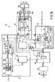
- the processing section 10 includes a picture enhancement processor 20, a progressive scan processor 30, and a common memory means 40, where information is fed forward from both the picture enhancement processor 20 and the memory means 40 to the progressive scan processor 30, and is also fed back from the memory means 40 to the picture enhancement processor (PEP) 20.
- the television processing section 10 further includes a picture in picture (PIP) processor 50 and multiplexers 52 and 54. Multiplexer 52 multiplexes main video data with PIP video data and provides a multiplexed field to the PEP 20.
- PIP picture in picture
- Multiplexer 54 is not required if the picture enhancement processor 20 is provided with certain hereinafter discussed control switching capabilities. However, without such capabilities, the multiplexer 54 acts to connect the common memory means 40 and/or the information multiplexed by multiplexer 52 to the picture enhancement processor 20.
- the picture enhancement processor is broadly comprised of a mixer 62, a control means 64, and a memory input select means 66.
- the mixer 62 obtains current video data (YUV) from multiplexer 52, video data (MO; memory output) from the common memory 40, and control information (K) from a control means, and processes the obtained data and information according to the equation (K.YUV) + (1-K).MO.
- the processed data is then provided to the progressive scan processor 30 and/or to the memory input select means 66.
- the PEP 20 of the invention is preferably capable of carrying out noise reduction or cross-color effect reduction.
- the preferred PEP is an integrated circuit, part # SAA9020 manufactured by Elcoma, a Philips Company, Eindhoven, The Netherlands.
- the memory means 40 is preferably a 64K X 4 dynamic RAM (DRAM) manufactured by Mitsubishi under part. # M5M4464L in conjunction with gate arrays. Or, if desired, the memory means 40 may be a charged coupled device, part # SAA9001 manufactured by Elcoma, a Philips Company, Eindhoven, The Netherlands.
- the progressive scan processor 30 is comprised of circuitry available to those in the art which is capable of conducting any one of several well known algorithms such as line repeat, field insertion, line averaging, and median filtering; the algorithm utilized in the preferred embodiment being median filtering.
- the PIP processor is likewise comprised of circuitry available to those in the art which is capable of providing a multiple PIP.
- the PIP processor 50 is capable of providing a field which includes three PIP images at a time, including a current image for at least one PIP.
- limited PIP associated memory such as two video memories, NEC part UPD41264, might be utilized.
- the PIP processor 50 is seen to be comprised of many different elements. Since PIP video is comprised of a composite signal, an analog decoder 501 is used to split the signal up, typically into its luminance component (Y), and into its color components. Due to the slower sampling of PIP signals, the decoded components are filtered by low pass filters 502a, 502b, 502c. The decoded components are then multiplexed by multiplexer 503, and converted into digital signals by the A/D converter 504. The digital signals are then forwarded to the PIP write unit 505 which writes the data into the PIP video DRAM 506, and which conducts vertical filtering of the signals.
- PIP write unit 505 which writes the data into the PIP video DRAM 506, and which conducts vertical filtering of the signals.
- Adder 507 in conjunction with multiplexer 508, PIP video DRAM 506, and FIFO 509.
- Adder 507 consecutively adds three lines together to get one weighted line of PIP.
- the DRAM 506 is used as storage in conducting the addition as well as for storing other weighted lines.
- the PIP video data is needed (e.g. a user of the television requests , typically via infrared commands, that a picture-in-picture function is to be accomplished)
- the PIP information is forwarded from the PIP video DRAM 506 to the PEP 20 via a multiplexer 52.
- multiplexer 52 is part of PIP read means 520 which adds borders to the PIPs and positions them properly as part of a larger picture.
- the other input into multiplexer 52 comes from the main video signal which is converted into a digital signal by A/D converter 180 and decoded into its components by digital decoder 182.
- the information received by multiplexer 52 is forwarded to the mixer 62 of PEP 20.
- the mixer processes the received information according to a predetermined function, with the value K being determined by the parameter control means 64.
- the parameter control means 64 includes a subtraction means 641, a low pass filter 642, a programmable ROM 644, and a multiplexer 645.
- the parameter control means 64 is a motion detector which determines how significantly a previous field differs from a current field. Where there is little motion, it is desirable to mix a good deal of the previous field into the present field, while where there is a lot of motion (much change), only a small amount of mixing is desirable.
- the subtraction means 641 functions to subtract a previous field (obtained from 2.56 megabit field memory 40 via multiplexer 54) from a current field.
- the difference is filtered by the low pass filter 642 which eliminates the high frequency components of the signal which are not relevant.
- the filtered difference signal is then rectified, as only the absolute difference is important (i.e. the direction of difference is unimportant).
- the rectified filtered difference signal is then fed to PROM 644 which preferably generates an exponential curve from the linear input signal, thereby advantageously causing the value of K to change extremely quickly when significant motion has been detected.
- Processed current data is forwarded to the progressive scan processor 30 both directly and via FIFO 190a which introduces a line delay. Delayed or stored information in the field memory 40 is likewise forwarded to the progressive scan processor 30 via FIFO 190b which is used to adjust the field memory to a full two hundred and sixty-three lines.
- the three different video sources are used by the median filter 302 for accomplishing the desired filtering, while the current video and line delayed "current video" may also be averaged by averaging means 304.
- a multiplexer 306 selects the source (usually median filter 302) of interpolated data, which is forwarded via FIFO 192a to a video D/A converter 198. Also forwarded to video D/A converter 198 is the current data via FIFO 192b, and the current video color component via color separator 308 and FIFO 192c.
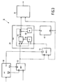
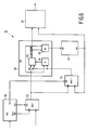
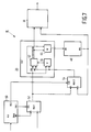
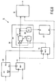
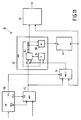
- the digital television processing section 10 is capable of operating in various modes, including direct video and direct video plus PIP ( Figures 2 and 3), noise reduction and noise reduction plus PIP ( Figures 4 and 5), cross-color reduction and cross-color reduction plus PIP ( Figures 6 and 7), stored picture and stored picture plus PIP ( Figures 8 and 9), freeze or recall picture ( Figure 10), and multiple PIP ( Figure 11).
- direct video and direct video plus PIP Figures 2 and 3
- noise reduction and noise reduction plus PIP Figures 4 and 5
- cross-color reduction and cross-color reduction plus PIP Figures 6 and 7
- stored picture and stored picture plus PIP Figures 8 and 9
- freeze or recall picture Figure 10
- multiple PIP Figure 11
- the direct video and direct video plus PIP modes are shown.
- the main video data is sent via multiplexer 52 to the mixer 62 of PEP 20, while in the direct video plus PIP mode, PIP data is processed in PIP processor 50, and the main video and PIP video data are multiplexed by multiplexer 52 and sent to the PEP mixer 62.
- the control parameter K of control means 64 is set to a value of one, the video data received at the mixer 62 is sent intact to the progressive scan processor 30 and the memory select means 66. From the memory select means 66, the data is forwarded to the memory means 40 where the data is delayed (i.e.
- the memory means 40 acts as a field delay). From the memory means, the now delayed data is forwarded to the progressive scan processor 30. Thus, both current data and delayed data are received by the progressive scan processor which provides, via known median filtering techniques, a non-interlaced video signal to the television picture tube.
- the value of parameter K supplied by the control means 64 is variable and is a function of the incoming signal and previously received signal.
- the main video signals, or the main video plus PIP video signals ( Figure 5) are received in the mixer 62 of PEP 20 from multiplexer 52, and are processed according to the previously discussed equation.
- the current video signals are also sent to the parameter control means 64.
- the output of mixer 62 is forwarded to both the progressive scan processor 30 and the memory select means 66.
- the memory select means 66 forwards the processed data to desired locations in common memory means 40 which acts as a field delay.
- the delayed information is then fed forward to the progressive scan processor 30 so that median filtering utilizing the current and delayed data may be accomplished.
- the delayed information is also fed back to the parameter control means 64 and the mixer 62 of the PEP 20 via multiplexer 54.
- the parameter control means 64 is able to compare the incoming signal with the processed and delayed previous signal, and thus provide a desired value K to the mixer. Also, with the varying signal K, the delayed processed signal (MO), and the current signal (Y,U,V) entering the mixer, the mixer 62 is able to properly accomplish the necessary processing.
- the memory means 40 acts both as a memory (field delay) for the PEP noise reduction algorithm which requires a feedback loop with field delayed data, as well as a memory for the progressive scan processor which requires a feed-forward arrangement with field delayed data for its median filtering. It is also of note, that the PIP data is also benefitted by the noise reduction carried out by the PEP 20, as it is the whole field, including the PIP data which is sent via multiplexer 52 to the PEP 20.
- the cross-color reduction and cross-color reduction plus PIP modes of Figures 6 and 7 are quite similar in data path arrangement to the noise reduction modes of Figures 4 and 5.
- the incoming data is set directly to the memory select means 66 and then to common memory 40.
- the common memory 40 which acts as a field delay, then forwards the delayed video data to the progressive scan processor 30 and to the mixer 62 of PEP 20.
- the parameter K is set to a value of one for the luminance component Y, and to a value of 0.5 for color components U and V.
- This arrangement permits the color signals from the incoming data field and the previous field to be averaged (via adding and multiplying by 0.5), thus canceling out the color subcarrier waveform.
- the common memory means 40 is acting as the memory means for the PEP feedback loop (mixer 62, to memory select means 66, to common memory means 40, to mixer 62), as well as the memory means for the progressive scan processor feed-forward loop (multiplexer 52, to memory input select 66, to common memory means 40, to progressive scan processor 30).
- the PIP video data benefits from the processing (cross color reduction) of the PEP 20.
- the stored picture and stored picture plus PIP modes of Figures 8 and 9 relate to the recall picture or freeze picture mode of Figure 10.
- the main video data (multiplexed with the PIP video data in Figure 9) is sent via multiplexer 52 to the PEP 20 where it is forwarded intact to the progressive scan processor 30.
- the video data contained in common memory means 40 is retained in the common memory means either by internal recirculation where the memory means is a charged coupled device, or by disabling any writing into memory where the memory means is a DRAM. No data is forwarded from the common memory means 40 to the progressive scan processor, and hence median filtering is not performed.
- the picture stored in the common memory means 40 may be recalled or may be used as a frozen picture as indicated in Figure 10.
- the picture in the common memory means 40 is forwarded to the mixer 62 of picture enhancement processor 20. With the parameter K being set to a value of zero, any PIP or main video data is ignored, and only the common memory means data is forwarded to the progressive scan processor 30. In order to maintain the data in the common memory means, the data in the common memory is either forwarded via the memory input select means 66 back into the common memory means 40 so that a recirculating feedback path (memory means 40, mux 54 to mixer 62, memory select means 66, memory means 40) is established, or the data is read from the memory means but not deleted therefrom. The data in the common memory means 40 is also forwarded to the progressive scan processor so that median filtering may be accomplished if desired. It will be appreciated that the data in memory means 40 may comprise main video data or main video data plus PIP data from at least one secondary channel.
- the multiple PIP mode of the invention is seen in Figure 11.
- main video data is not viewed (although, main video could be active if desired).
- the PIP video data is processed in the PIP processor 50, and sent through multiplexer 52 which does not (in the preferred embodiment) process the main video data.
- the data is sent to multiplexer 54 and then to the memory output (MO) port of the mixer 62.
- the data is therefore treated in a similar manner to the recalled or frozen picture mode of Figures 9 and 10 in that the parameter K is set to zero, and the data which is forwarded from mixer 62 to the progressive scan processor 30 is the non-processed, intact data which was received at the MO port of the mixer 62.
- multiplexer 54 could be located between the memory select means 66 of the PEP 20 and the memory means 40. With such an arrangement, the multiple PIP data would first be stored in memory 40 prior to being forwarded to the memory output (MO) port of the mixer 62. Regardless, parameter K would still be set to zero.
- data from the mixer 62 is forwarded both to the progressive scan processor 30 and to the common memory means 40.
- the information in the common memory means 40 is then recirculated via multiplexer 54 back to the MO port of the mixer 62 of the PEP 20.
- up to nine PIPs may be recirculated in a "frozen" mode.
- a PIP field may be processed live by the PIP processor in each entire screen field frame, that live information may be forwarded to multiplexer 54 and inserted in its proper location by having the PIP processor 50 properly toggling the select port of the multiplexer 54.
- the timing of the selection will depend on which PIP is to be updated. If desired, the PIP to be updated can be changed each cycle such that the PIPs will update at approximately one-ninth the normal update speed.
- the multiplexer 54 could be controlled to insert those plurality of fields into the data path. In this manner, more than one live PIP could be provided either as part of a nine or more PIP picture or as part of a main video picture. Also, if the PEP 20 had a means for instantaneously controlling the parameter control means 64 such that it could instantly provide values of zero and one for K (e.g. a control port on the K control means under the control of, e.g. the PIP processor), the need for multiplexer 54 would be obviated. Thus, as live PIP or main video data were provided via multiplexer 52, the K value would be set to one. When the recirculated (frozen) data from the multiple PIPs were provided from the common memory means 40, the K value would be set to zero.
- common memory means 40 was described as comprising a charged coupled device or a DRAM, any memory which is capable of receiving and sending information in a first-in-first-out (FIFO) manner is acceptable. In fact, if desired, memories other than FIFOs could be utilized provided minor modifications were made in the data paths. Moreover, while data paths have been described, it will be appreciated that data may be sent and in essence ignored (such as the MO data when K is set to one, or data reaching a multiplexer when the multiplexer is forwarding data from another channel), or the data need not be sent at all (e.g. it may be overwritten in memory). For purposes herein, the two situations are equivalent, and terminology suggesting one state or the other is to be read broadly to include the other.
- processing data is likewise to be read broadly to be inclusive of multiplication by 1 such as the processing of current video data when K is set to a value of one, or the processing of delayed data from memory when K is set to a value of zero.
- YUV data is to be read broadly as to be inclusive of RGB or other color information of a different format. Therefore, it will be apparent to those skilled in the art that yet other changes and modifications may be made to the invention as described without departing from the scope of the invention as so claimed.
Landscapes
- Engineering & Computer Science (AREA)
- Multimedia (AREA)
- Signal Processing (AREA)
- Computer Graphics (AREA)
- Processing Of Color Television Signals (AREA)
- Studio Circuits (AREA)
Claims (12)
- Fernsehverarbeitungsteil mit:
Speichermitteln (40) zum Liefern verzögerter Videodaten (MO);
einem Bildverbesserungsprozessor (20) mit einem Mischer (62) zum Empfangen aktueller Videodaten (YUV) von wenigstens einer Hauptvideodatenquelle und der genannten verzögerten Videodaten (MO) von den genannten Speichermitteln (40) zum Mischen der genannten aktuellen Videodaten (YUV) mit den genannten verzögerten Videodaten (MO) zum Liefern von verarbeiteten Videodaten, und mit Parametersteuermitteln (64) zum Liefern eines Parameters (K) zur Steuerung des Mischverhältnisses des genannten Mischers (62), und mit Speicherselektionsmitteln (66) zum Liefern der genannten aktuellen Videodaten (YUV) oder der genannten verarbeiteten Videodaten zu den genannten Speichermitteln (40); und
einem progressiven Abtastprozessor (30) zum Empfangen der genannten verarbeiteten Videodaten von dem genannten Bildverbesseungsprozessor (20) sowie der genannten verzögerten Videodaten (MO) von den genannten Speichermitteln (40). - Fernsehverarbeitungsteil nach Anspruch 1, wobei der genannte Mischer (62) vorgesehen ist zum Liefern der genannten verarbeiteten Videodaten entsprechend einer Beziehung: K.YUV + (1-K).MO, wobei der genannte Parameter (K) einen Wert zwischen Null b/e eins hat, YUV die genannten aktuellen Videodaten sind und MO die genannten verzögerten Videodaten sind.
- Fernsehverarbeitungsteil nach Anspruch 2, wobei in einer Farbbeeinflussungsverringerungsbetriebsart die genannten aktuellen Videodaten (YUV) von den genannten Speicherselektionsmitteln (66) zu den genannten Speichermnitteln (40) geliefert werden, und die genannten Parametersteuermittel (64) einen Wert von 0,5 schaffen für den genannten Parameter (K) für Farbanteile (UV) der genannten aktuellen Videodaten (YUV) und der verzögerten Videodaten (MO), und einen Wert gleich Eins für den Parameter (K) für Leuchtdichteanteile (Y) der genannten aktuellen Videodaten (YUV) und der verzögerten Videodaten (MO).
- Fernsehverarbeitungsteil nach Anspruch 1, wobei in wenigsten einer der Speicherbild-, Wiederaufruf- und Gefrierbetriebsarten Daten, die in den genannten Speichermitteln (40) empfangen und gespeichert wurden mit den genannten Speichermitteln (40) festgehalten werden.
- Fernsehverarbeitungsteil nach Anspruch 2, wobei in einer Wiederaufruf- oder Gefrierbetriebsart die genannten Parametersteuermittel (64) einen Wert gleich Null für den genannten Parameter (K) schaffen.
- Fernsehverarbeitungsteil nach Anspruch 1, weiterhin mit:
Bild-in-Bild-Verarbeitungsmitteln (50) zum Empfangen sekundärer Videodaten von einer sekundären Quelle zur Verarbeitung der genannten sekundären Videodaten; und
ersten Multiplexermitteln (52) zum Empfangen von Hauptvideodaten von einer Hauptvideoquelle und der genannten verarbeiteten sekundären Videodaten zum Multiplexen der genannten Hauptvideodaten und der genannten verarbeiteten sekundären Videodaten, und zum Zuführen der genannten gemultiplexten Daten als genannte aktuelle Videodaten (YUV) zu dem genannten Bildverbesserungsprozessor (20). - Fernsehverarbeitungsteil nach Anspruch 1, wobei in einer Mehrfach-Bildin-Bild-Betriebsart die genannten Videodaten (YUV) sekundäre Videodaten von wenigstens einer sekundären Videoquelle enthalten, und der genannte Mischer (62) ein Datenfeld aus aktuellen Videodaten von den genannten ersten Multiplexermitteln (52) und verzögerten Videodaten aus den genannten Speichermitteln (40) empfängt.
- Fernsehverarbeitungsteil nach Anspruch 7, wobei der genannte Mischer (62) ein erstes Datenport zum Empfangen der genannten aktuellen Videodaten (YUV) aufweist, sowie ein zweites Datenport (MO), wobei der Fernsehverarbeitungsteil weiterhin zweite Multiplexermittel (54) aufweist zum Multiplexen der genannten aktuellen Videodaten aus den genannten ersten Multiplexermitteln (52) und der genannten verzögerten Videodaten aus den genannten Speichermitteln (40) zum Liefern gemultiplexter Daten als das genannte Datenfeld zu dem genannten zweiten Datenport (MO) des genannten Mischers (62), und wobei die genannten Parametersteuermittel (64) einen Wert gleich Null für den genannten Parameter (K) schaffen.
- Fernsehverarbeitungsteil nach Anspruch 6, wobei in einer Rauschunterdrückung-mit-PIP-Betriebsart die genannten Parametersteuermittel (64) die genannten aktuellen Videodaten (YUV) und die genannten verzögerten Videodaten (MO) empfangen zur Bestimmung eines Wertes für den genannten Parameter (K), der als Funktion der genannten aktuellen Videodaten (YUV) und der genannten verzögerten Videodaten (MO) variabel ist.
- Fernsehverarbeitungsteil nach Anspruch 6, wobei die genannten aktuellen Videodaten (YUV) aus den genannten Hauptvideodaten und den genannten sekundären Videodaten von wenigstens zwei sekundären Videoquellen bestehen, wobei die genannten Bild-in-Bild-Verarbeitungsmittel (50) vorgesehen sind zum Verarbeiten der genannten sekundären Videodaten von den genannten sekundären Videoquellen um nur ein aktuelles Bild-in-Bild und wenigstens ein gefrorenes Bild-in-Bild zu liefern.
- Fernsehverarbeitungsteil nach Anspruch 6, wobei in einer Mehrfach-Bildin-Bild-Betriebsart die genannten ersten Multiplexermittel (52) verarbeitete sekundäre Videodaten wenigstens zweier sekundärer Quellen von den genannten Bild-in-Bild-Verarbeitungsmitteln (50) empfangen, wobei der Fernsehverarbeitungsteil weiterhin die nachfolgenden Elemente aufweist:
zweite Multiplexermittel (54) zum Empfangen der genannten verzögerten Videodaten (MO), und wobei über den genannten Mischer (62) und die genannten Speicherselektionsmittel (66) ein Eingang der genannten Speichermittel (40) mit einem Ausgang der genannten zweiten Multiplexermittel (54) gekoppelt ist. - Fernsehverarbeitungsteil nach den Ansprüchen 2 und 11, wobei der genannte Mischer (62) ein erstes Datenport aufweist zum Empfangen aktueller Videodaten (YUV) und ein zweites Datenport zum Empfangen wenigstens der genannten verzögerten Videodaten (MO), und wobei in der genannten Mehrfach-Bild-in-Bild-Betriebsart das genannte zweite Datenport (MO) mit dem genannten Ausgang des genannten zweiten Multiplexers (54) gekoppelt ist und wobei die genannten Parametersteuermittel (64) einen Wert gleich Null für den genannten Parameter (K) schaffen.
Applications Claiming Priority (2)
| Application Number | Priority Date | Filing Date | Title |
|---|---|---|---|
| US166279 | 1988-03-10 | ||
| US07/166,279 US4809069A (en) | 1988-03-10 | 1988-03-10 | Multifunction memory for digital television |
Publications (3)
| Publication Number | Publication Date |
|---|---|
| EP0332266A2 EP0332266A2 (de) | 1989-09-13 |
| EP0332266A3 EP0332266A3 (de) | 1991-08-07 |
| EP0332266B1 true EP0332266B1 (de) | 1995-06-07 |
Family
ID=22602593
Family Applications (1)
| Application Number | Title | Priority Date | Filing Date |
|---|---|---|---|
| EP89200538A Expired - Lifetime EP0332266B1 (de) | 1988-03-10 | 1989-03-06 | Vielfunktionsspeicher für digitales Fernsehen |
Country Status (5)
| Country | Link |
|---|---|
| US (1) | US4809069A (de) |
| EP (1) | EP0332266B1 (de) |
| JP (1) | JPH01296864A (de) |
| CA (1) | CA1308478C (de) |
| DE (1) | DE68922924T2 (de) |
Families Citing this family (28)
| Publication number | Priority date | Publication date | Assignee | Title |
|---|---|---|---|---|
| JPH01264377A (ja) * | 1988-04-15 | 1989-10-20 | Hitachi Ltd | ビデオプリンタ |
| JP2555141B2 (ja) * | 1988-04-15 | 1996-11-20 | 株式会社日立製作所 | 画像処理装置 |
| GB2219451A (en) * | 1988-05-31 | 1989-12-06 | Plessey Co Plc | Frequency synthesiser |
| KR930004307B1 (ko) * | 1989-06-15 | 1993-05-22 | 샤프 가부시끼가이샤 | 영상 신호의 주사선 수 변환 장치, 이것을 사용한 다운 컨버터 및 그 화면 텔레비젼 수상기 |
| US5016103A (en) * | 1989-08-17 | 1991-05-14 | Zenith Electronics Corporation | Spatial scan converter with vertical detail enhancement |
| US5093722A (en) * | 1990-03-01 | 1992-03-03 | Texas Instruments Incorporated | Definition television digital processing units, systems and methods |
| JP3187851B2 (ja) * | 1990-03-01 | 2001-07-16 | テキサス インスツルメンツ インコーポレイテツド | 鮮明度を改良したテレビ |
| US5111296A (en) * | 1990-04-19 | 1992-05-05 | Thomson Consumer Electronics, Inc. | Data transfer from a television receiver having picture-in-picture capability to an external computer |
| US5113259A (en) * | 1990-04-19 | 1992-05-12 | Thomson Consumer Electronics, Inc. | Data transfer from an external computer to a television receiver having picture-in-picture capability |
| DE4031785C2 (de) * | 1990-10-08 | 1996-07-04 | Broadcast Television Syst | Verfahren zur Reduktion von Rauschen in Videosignalen |
| US5202765A (en) * | 1991-05-06 | 1993-04-13 | Thomson Consumer Electronics, Inc. | Television receiver with picture in picture and non-linear processing |
| US5384865A (en) * | 1992-06-01 | 1995-01-24 | Eastman Kodak Company | Adaptive, hybrid median filter for temporal noise suppression |
| US5499060A (en) * | 1994-01-04 | 1996-03-12 | Texas Instruments Incorporated | System and method for processing video data |
| EP0680224B1 (de) * | 1994-04-27 | 2002-11-13 | Co.Ri.M.Me. Consorzio Per La Ricerca Sulla Microelettronica Nel Mezzogiorno | Rauschvermindernde Filterung und interpolierende Abtastratenwandlung für digitale Videosignale, gesteuert durch mit Fuzzy-Logik detektierte Zwischenfeld-Korrelationsinformation |
| DE4429287A1 (de) * | 1994-08-18 | 1996-02-29 | Siemens Ag | Verfahren und Schaltungsanordnung zur Bild-im-Bild-Einblendung |
| KR0170657B1 (ko) * | 1994-08-31 | 1999-03-30 | 김광호 | 색신호에 있는 윤곽을 보정하는 방법 및 이를 칼라 비디오기기에서 구현하기 위한 회로 |
| DE69426820T2 (de) * | 1994-09-30 | 2001-08-16 | Stmicroelectronics S.R.L., Agrate Brianza | Vorrichtung und Verfahren zum Filtern von Videobildern |
| KR960020415A (ko) * | 1994-11-23 | 1996-06-17 | 윌리엄 이. 힐러 | 디지탈 텔레비젼을 위한 특수 기능 |
| DE4445803A1 (de) * | 1994-12-21 | 1996-06-27 | Siemens Ag | Fernsehgerät |
| DE19808005A1 (de) * | 1998-02-26 | 1999-09-02 | Philips Patentverwaltung | Anordnung zum Bearbeiten von Videosignalen |
| US7373650B1 (en) * | 2000-02-01 | 2008-05-13 | Scientific-Atlanta, Inc. | Apparatuses and methods to enable the simultaneous viewing of multiple television channels and electronic program guide content |
| US6414719B1 (en) * | 2000-05-26 | 2002-07-02 | Sarnoff Corporation | Motion adaptive median filter for interlace to progressive scan conversion |
| US8677423B2 (en) * | 2000-12-28 | 2014-03-18 | At&T Intellectual Property I, L. P. | Digital residential entertainment system |
| US8601519B1 (en) * | 2000-12-28 | 2013-12-03 | At&T Intellectual Property I, L.P. | Digital residential entertainment system |
| EP1292133A1 (de) * | 2001-09-06 | 2003-03-12 | Koninklijke Philips Electronics N.V. | Mehrfachbildanzeige |
| KR100720339B1 (ko) * | 2005-09-15 | 2007-05-22 | 삼성전자주식회사 | 영상처리장치 |
| US20110102671A1 (en) * | 2009-10-29 | 2011-05-05 | Apple Inc. | Picture in Picture Video Display for Low Power Device |
| US8941706B2 (en) | 2010-04-07 | 2015-01-27 | Apple Inc. | Image processing for a dual camera mobile device |
Family Cites Families (12)
| Publication number | Priority date | Publication date | Assignee | Title |
|---|---|---|---|---|
| GB1515551A (en) * | 1975-04-25 | 1978-06-28 | British Broadcasting Corp | Noise reduction in electrical signals |
| FR2393489A2 (fr) * | 1977-03-07 | 1978-12-29 | Marconi Co Ltd | Procede de reduction du bruit dans des signaux electriques |
| EP0004728B1 (de) * | 1978-04-03 | 1982-04-28 | British Broadcasting Corporation | Rauschverminderung in elektrischen Signalen |
| JPS5511678A (en) * | 1978-07-11 | 1980-01-26 | Nippon Hoso Kyokai <Nhk> | Noise reduction device |
| JPS55102972A (en) * | 1979-01-31 | 1980-08-06 | Hitachi Ltd | Removal unit for noise of picture |
| SU809657A1 (ru) * | 1979-04-02 | 1981-02-28 | Предприятие П/Я А-1772 | Устройство подавлени шумовВ ТЕлЕВизиОННОМ СигНАлЕ |
| US4494140A (en) * | 1981-01-22 | 1985-01-15 | Micro Consultants Limited | T.V. apparatus for movement control |
| DE3121597C3 (de) * | 1981-05-30 | 1993-09-30 | Bosch Gmbh Robert | System zur Verminderung des Rauschens in einem Fernseh-Bildsignal |
| DE3319438A1 (de) * | 1983-05-28 | 1984-11-29 | Robert Bosch Gmbh, 7000 Stuttgart | System zur verminderung des rauschens in einem fernsehsignal |
| US4623913A (en) * | 1984-04-13 | 1986-11-18 | Rca Corporation | Progressive scan video processor |
| US4748498A (en) * | 1985-11-19 | 1988-05-31 | Matsushita Electric Industrial Co., Ltd. | Luminance signal processing circuit with recursive filter for reducing noise while retaining a high vertical resolution |
| US4665438A (en) * | 1986-01-03 | 1987-05-12 | North American Philips Corporation | Picture-in-picture color television receiver |
-
1988
- 1988-03-10 US US07/166,279 patent/US4809069A/en not_active Expired - Fee Related
-
1989
- 1989-03-06 EP EP89200538A patent/EP0332266B1/de not_active Expired - Lifetime
- 1989-03-06 DE DE68922924T patent/DE68922924T2/de not_active Expired - Fee Related
- 1989-03-07 CA CA000592940A patent/CA1308478C/en not_active Expired - Lifetime
- 1989-03-09 JP JP1055228A patent/JPH01296864A/ja active Pending
Also Published As
| Publication number | Publication date |
|---|---|
| US4809069A (en) | 1989-02-28 |
| CA1308478C (en) | 1992-10-06 |
| DE68922924D1 (de) | 1995-07-13 |
| EP0332266A2 (de) | 1989-09-13 |
| EP0332266A3 (de) | 1991-08-07 |
| DE68922924T2 (de) | 1996-01-04 |
| JPH01296864A (ja) | 1989-11-30 |
Similar Documents
| Publication | Publication Date | Title |
|---|---|---|
| US4809069A (en) | Multifunction memory for digital television | |
| EP0391094B1 (de) | Fernseh-Abtastzeilenverdoppler mit einem zeitlichen Mittelwertfilter | |
| US6008860A (en) | Television system with provisions for displaying an auxiliary image of variable size | |
| JP2715172B2 (ja) | 信号濾波装置 | |
| KR100209852B1 (ko) | 나란한 화상 디스플레이를 위한 자동 동기화 스위치 | |
| US5594467A (en) | Computer based display system allowing mixing and windowing of graphics and video | |
| US5027212A (en) | Computer based video/graphics display system | |
| US4967271A (en) | Television scan line doubler including temporal median filter | |
| US5430494A (en) | Independent horizontal panning for side-by-side pictures | |
| JPH05508061A (ja) | ビデオ信号制御装置 | |
| EP0773683B1 (de) | Steuerung von Abwärts-Videoformatumwandlung | |
| US20040131276A1 (en) | Region-based image processor | |
| US5680176A (en) | Apparatus for controlling caption display on a wide aspect ratio | |
| EP0424995B1 (de) | Bildwiederholspeicher für Spezialeffekte | |
| JPH08251504A (ja) | ビデオディスプレイシステム | |
| US5663759A (en) | Feature processor for a digital camera | |
| US5867225A (en) | Multiple mode controlling signal processing apparatus | |
| KR0160158B1 (ko) | 병렬 화상을 위한 독립 수평 패닝이 가능한 영상 표시 장치 | |
| JPH10513015A (ja) | レターボックスの表示制御 | |
| US5822009A (en) | Video down-conversion | |
| GB2307129A (en) | Video down-conversion | |
| JPH01264376A (ja) | 複数画面を表示可能とする信号処理回路 | |
| KR100208692B1 (ko) | 메모리 공유 영상 처리 장치 | |
| KR910009510B1 (ko) | 고해상도 텔레비젼에 있어서 잡음감소회로 | |
| JPH06225191A (ja) | カメラ一体型ビデオテープレコーダ |
Legal Events
| Date | Code | Title | Description |
|---|---|---|---|
| PUAI | Public reference made under article 153(3) epc to a published international application that has entered the european phase |
Free format text: ORIGINAL CODE: 0009012 |
|
| AK | Designated contracting states |
Kind code of ref document: A2 Designated state(s): DE FR GB IT |
|
| PUAL | Search report despatched |
Free format text: ORIGINAL CODE: 0009013 |
|
| AK | Designated contracting states |
Kind code of ref document: A3 Designated state(s): DE FR GB IT |
|
| RHK1 | Main classification (correction) |
Ipc: H04N 5/21 |
|
| 17P | Request for examination filed |
Effective date: 19920410 |
|
| RAP1 | Party data changed (applicant data changed or rights of an application transferred) |
Owner name: PHILIPS ELECTRONICS NORTH AMERICA CORPORATION |
|
| 17Q | First examination report despatched |
Effective date: 19940201 |
|
| GRAA | (expected) grant |
Free format text: ORIGINAL CODE: 0009210 |
|
| AK | Designated contracting states |
Kind code of ref document: B1 Designated state(s): DE FR GB IT |
|
| REF | Corresponds to: |
Ref document number: 68922924 Country of ref document: DE Date of ref document: 19950713 |
|
| ITF | It: translation for a ep patent filed | ||
| ET | Fr: translation filed | ||
| PLBE | No opposition filed within time limit |
Free format text: ORIGINAL CODE: 0009261 |
|
| STAA | Information on the status of an ep patent application or granted ep patent |
Free format text: STATUS: NO OPPOSITION FILED WITHIN TIME LIMIT |
|
| 26N | No opposition filed | ||
| PGFP | Annual fee paid to national office [announced via postgrant information from national office to epo] |
Ref country code: GB Payment date: 19970228 Year of fee payment: 9 |
|
| PGFP | Annual fee paid to national office [announced via postgrant information from national office to epo] |
Ref country code: FR Payment date: 19970325 Year of fee payment: 9 |
|
| PGFP | Annual fee paid to national office [announced via postgrant information from national office to epo] |
Ref country code: DE Payment date: 19970523 Year of fee payment: 9 |
|
| PG25 | Lapsed in a contracting state [announced via postgrant information from national office to epo] |
Ref country code: GB Free format text: LAPSE BECAUSE OF NON-PAYMENT OF DUE FEES Effective date: 19980306 |
|
| PG25 | Lapsed in a contracting state [announced via postgrant information from national office to epo] |
Ref country code: FR Free format text: THE PATENT HAS BEEN ANNULLED BY A DECISION OF A NATIONAL AUTHORITY Effective date: 19980331 |
|
| GBPC | Gb: european patent ceased through non-payment of renewal fee |
Effective date: 19980306 |
|
| PG25 | Lapsed in a contracting state [announced via postgrant information from national office to epo] |
Ref country code: DE Free format text: LAPSE BECAUSE OF NON-PAYMENT OF DUE FEES Effective date: 19981201 |
|
| REG | Reference to a national code |
Ref country code: FR Ref legal event code: ST |
|
| PG25 | Lapsed in a contracting state [announced via postgrant information from national office to epo] |
Ref country code: IT Free format text: LAPSE BECAUSE OF NON-PAYMENT OF DUE FEES Effective date: 20050306 |