EP0332059B1 - Lagerung für eine schwenkbare Abdeckplatte - Google Patents
Lagerung für eine schwenkbare Abdeckplatte Download PDFInfo
- Publication number
- EP0332059B1 EP0332059B1 EP89103711A EP89103711A EP0332059B1 EP 0332059 B1 EP0332059 B1 EP 0332059B1 EP 89103711 A EP89103711 A EP 89103711A EP 89103711 A EP89103711 A EP 89103711A EP 0332059 B1 EP0332059 B1 EP 0332059B1
- Authority
- EP
- European Patent Office
- Prior art keywords
- receiving part
- wall
- mounting according
- cover plate
- slot
- Prior art date
- Legal status (The legal status is an assumption and is not a legal conclusion. Google has not performed a legal analysis and makes no representation as to the accuracy of the status listed.)
- Expired - Lifetime
Links
Images


Classifications
-
- B—PERFORMING OPERATIONS; TRANSPORTING
- B60—VEHICLES IN GENERAL
- B60R—VEHICLES, VEHICLE FITTINGS, OR VEHICLE PARTS, NOT OTHERWISE PROVIDED FOR
- B60R5/00—Compartments within vehicle body primarily intended or sufficiently spacious for trunks, suit-cases, or the like
- B60R5/04—Compartments within vehicle body primarily intended or sufficiently spacious for trunks, suit-cases, or the like arranged at rear of vehicle
- B60R5/044—Compartments within vehicle body primarily intended or sufficiently spacious for trunks, suit-cases, or the like arranged at rear of vehicle luggage covering means, e.g. parcel shelves
-
- E—FIXED CONSTRUCTIONS
- E05—LOCKS; KEYS; WINDOW OR DOOR FITTINGS; SAFES
- E05D—HINGES OR SUSPENSION DEVICES FOR DOORS, WINDOWS OR WINGS
- E05D11/00—Additional features or accessories of hinges
- E05D11/10—Devices for preventing movement between relatively-movable hinge parts
- E05D11/1028—Devices for preventing movement between relatively-movable hinge parts for maintaining the hinge in two or more positions, e.g. intermediate or fully open
- E05D11/105—Devices for preventing movement between relatively-movable hinge parts for maintaining the hinge in two or more positions, e.g. intermediate or fully open the maintaining means acting perpendicularly to the pivot axis
- E05D11/1057—Devices for preventing movement between relatively-movable hinge parts for maintaining the hinge in two or more positions, e.g. intermediate or fully open the maintaining means acting perpendicularly to the pivot axis specially adapted for vehicles
-
- E—FIXED CONSTRUCTIONS
- E05—LOCKS; KEYS; WINDOW OR DOOR FITTINGS; SAFES
- E05Y—INDEXING SCHEME ASSOCIATED WITH SUBCLASSES E05D AND E05F, RELATING TO CONSTRUCTION ELEMENTS, ELECTRIC CONTROL, POWER SUPPLY, POWER SIGNAL OR TRANSMISSION, USER INTERFACES, MOUNTING OR COUPLING, DETAILS, ACCESSORIES, AUXILIARY OPERATIONS NOT OTHERWISE PROVIDED FOR, APPLICATION THEREOF
- E05Y2900/00—Application of doors, windows, wings or fittings thereof
- E05Y2900/50—Application of doors, windows, wings or fittings thereof for vehicles
- E05Y2900/53—Type of wing
- E05Y2900/531—Doors
Definitions
- the invention relates to a bearing for a pivotable cover plate above the trunk of motor vehicles according to the preamble of claim 1.
- a bearing is e.g. known from DE-B-2 647 104.
- This known storage is arranged on the side wall.
- the front edge of the cover plate must be brought into engagement with the two guide slots in the bearing. This is difficult since, in order to avoid tilting, it is necessary to insert the cover plate uniformly into the slots of the guide arranged on the two side walls. Furthermore, the bracket protruding from the side walls may interfere with the loading process.
- the actual mounting is advantageously integrated into the side wall of the vehicle, so that the cover plate can be brought close to the side wall, with a simple release and fastening of the cover plate being possible.
- the receiving part has a round front plate with an axially extending guide flange arranged at its edge, which is in sliding engagement with the wall of the opening, a completely closed arrangement of the holder is advantageously achieved.
- the receiving part has a slot which is arranged in the central part of the front panel and extends to its edge and extends axially from the front panel to the rear.
- the slot-shaped design of the holder allows a very simple construction of the receiving part, so that it can be manufactured inexpensively.
- the slot is essentially cuboid, bounded by a stop wall in the insertion direction of the cover plate, a rear wall in the axial direction of the receiving part and by an upper and lower wall and is open in the area of the front plate and the edge.
- the cover plate can assume various raised positions, it is provided that the receiving part has locking projections on its rear side.
- the locking projections are expediently arranged on the back of the rear wall of the slot, extending from the edge to the vicinity of the axis.
- a shaft screw extending in the axial direction is arranged on the back of the rear wall of the slot.
- the rear wall has a locking opening in the area of the stop wall.
- the end shield advantageously has a substantially square bearing surface with locking grooves arranged on the front, corresponding to the locking projections of the receiving part and a central opening for the socket screw of the receiving part, and a fastening section extending from the bearing surface.
- the bearing surface has on its rear side a spring counter bearing surface against which a coil spring arranged on the shaft screw is supported, the other end of which rests against a nut that can be screwed onto the screw.
- the receiving part, the end shield and the molded part are designed as injection molded parts made of plastic.
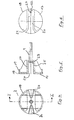
- 1 denotes the tailgate of a passenger car, which has a rear window 2.
- the cover plate 3 above the trunk 4 is articulated with its two front corners in a storage 5 each.
- the bearings 5 enable the cover plate 3 to be pivoted into an approximately horizontal closed position (FIG. 1), an open position (FIG. 2) and the cover plate 3 to be removed.
- the bearing 5 is shown in FIGS. 3 to 9 in detail. It comprises a molded part 6, a receiving part 7, a bearing plate 8 and a helical spring arranged around a shaft screw 9 and a nut which can be screwed onto the helical spring (both not shown).
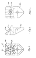
- the molded part 6 (see Fig. 3) is essentially wedge-shaped, i.e. it widens forward from its rear end aligned with the side wall of the vehicle, the widening part being covered by an upper wall 10.
- a guide slot 12 is formed in the side wall 11 and opens into a cylindrical opening 13 running transversely to the longitudinal axis of the molded part 6.
- Behind the cylindrical opening 13, seen in the longitudinal direction of the molded part 6, the side wall 11 of the molded part 6 is stepped towards the side wall of the vehicle and extends to an arm-shaped fastening section 14 of the molded part 6.
- a mounting opening 15 which can be closed by means of a cover 16 is provided.
- the molded part 6 is expediently designed as an injection molded part made of plastic.
- the cylindrical opening 13 in the molded part 6 serves to receive the receiving part 7 (see FIGS. 4 to 6).
- the receiving part 7 has a round front plate 17 with a guide flange 19 arranged on its edge 18 and extending in the axial direction, which is in sliding engagement with the opening 13. That is, the guide flange 19 extends in a circular shape from the edge 18 of the front panel 17 into the opening 13.
- a slot 20 extending up to its edge 18 is arranged in the central part of the front panel 17, i.e. running through its center.
- the slot 20 has a depth in its longitudinal direction which corresponds approximately to the diameter of the front plate 17, and widens in its front region, two end flanges 21 extending in the circumferential direction of the front plate 17 being provided at its front end.
- the slot 20 is essentially cuboid and is delimited by a stop wall 22 in the insertion direction of the cover plate 3, a rear wall 23 in the axial direction of the receiving part 7 and by an upper and lower wall 24, 25, and is in the region of the front plate 17 and the edge 18 open.
- the receiving part 7 On its rear side, the receiving part 7 has locking projections 26, the locking projections 26 being arranged on the rear of the rear wall 23 of the slot 20, extending from the edge 18 to the vicinity of the axis.
- the rear wall 23 of the slot 20 On the back of the rear wall 23 of the slot 20 there is also a shaft screw 9 which extends in the axial direction of the receiving part 7 and which serves to connect the receiving part 7 to the end shield 8 described below. Furthermore, the rear wall 23 in the region of the connecting wall 22 has a locking opening 27 into which a corresponding projection on the cover plate (not shown) can engage in order to prevent the cover plate from being unintentionally released.
- the bearing plate 8 which engages with the receiving part 7 in the assembled state and is biased against the receiving part 7 by means of a spring arranged on the shaft screw 9, has a substantially square bearing surface 28 with locking grooves 29 arranged on the front.
- the locking grooves 29 correspond to the locking projections 26 of the receiving part 7, and they can have any shape. In the illustrated embodiment, they extend in a star shape from the center of the bearing plate 8 to the outside, six locking grooves 29 being provided which can be brought into engagement with the two locking projections 26 on the receiving part 7, so that three locking positions are possible.
- the locking grooves 29 are arranged at an angular distance of about 60 °.
- the bearing surface 28 has a spring counter bearing surface 30 on its rear side, which is arranged around a central opening 31 in the bearing plate 8.
- the above-mentioned shaft screw extends through the opening 31.
- the bearing plate 8 is fastened with its fastening section 32 to the side wall of the vehicle or to the molded part 6. Then the receiving part 7 is arranged in the opening 13, its socket screw 9 extending through the central opening 31 in the bearing plate 8.
- the bearing plate 8 is attached to the shaft of the shaft screw 9 by means of a coil spring which is supported against the spring counter bearing surface 30 pressed against the receiving part 7, the other end of the helical spring resting against a nut which can be screwed onto the shaft screw 9.
- the pretension can be adjusted as desired by tightening the nut accordingly.
- the pre-assembled molded part 7 is screwed onto the side wall of the vehicle.
Landscapes
- Engineering & Computer Science (AREA)
- Mechanical Engineering (AREA)
- Vehicle Step Arrangements And Article Storage (AREA)
- Vehicle Interior And Exterior Ornaments, Soundproofing, And Insulation (AREA)
Applications Claiming Priority (2)
| Application Number | Priority Date | Filing Date | Title |
|---|---|---|---|
| DE3808083A DE3808083C1 (enExample) | 1988-03-11 | 1988-03-11 | |
| DE3808083 | 1988-03-11 |
Publications (2)
| Publication Number | Publication Date |
|---|---|
| EP0332059A1 EP0332059A1 (de) | 1989-09-13 |
| EP0332059B1 true EP0332059B1 (de) | 1991-01-16 |
Family
ID=6349449
Family Applications (1)
| Application Number | Title | Priority Date | Filing Date |
|---|---|---|---|
| EP89103711A Expired - Lifetime EP0332059B1 (de) | 1988-03-11 | 1989-03-03 | Lagerung für eine schwenkbare Abdeckplatte |
Country Status (3)
| Country | Link |
|---|---|
| EP (1) | EP0332059B1 (enExample) |
| DE (2) | DE3808083C1 (enExample) |
| ES (1) | ES2019708B3 (enExample) |
Families Citing this family (7)
| Publication number | Priority date | Publication date | Assignee | Title |
|---|---|---|---|---|
| DE19735439A1 (de) * | 1997-08-16 | 1999-02-18 | Volkswagen Ag | Anordnung mit einer Gepäckraumabdeckung in einem Fahrzeug |
| DE19856741C2 (de) * | 1998-12-09 | 2001-02-01 | Baumeister & Ostler Gmbh Co | Laderaumabdeckung bzw. Hutablage mit beweglichen Eckstücken |
| FR2794701B1 (fr) * | 1999-06-11 | 2001-08-31 | Sommer Ind | Dispositif pour retenir et articuler une tablette arriere amovible de vehicule automobile |
| DE102006052598B4 (de) * | 2006-11-08 | 2022-06-09 | Volkswagen Ag | Abdeckvorrichtung für einen Gepäckraum eines Kraftfahrzeuges |
| JP5342500B2 (ja) * | 2010-05-21 | 2013-11-13 | スズキ株式会社 | リアパーセルシェルフのヒンジ構造 |
| EP2492146B1 (en) * | 2011-02-25 | 2014-04-09 | National Electric Vehicle Sweden AB | Automatic parcel shelf |
| EP2716499B1 (fr) | 2012-10-05 | 2016-04-27 | Faurecia Innenraum Systeme GmbH | Ensemble arrière de véhicule automobile et véhicule automobile associé |
Family Cites Families (2)
| Publication number | Priority date | Publication date | Assignee | Title |
|---|---|---|---|---|
| DE2647104C3 (de) * | 1976-10-19 | 1981-11-19 | Audi Nsu Auto Union Ag, 7107 Neckarsulm | Lagerung für eine schwenkbare Abdeckplatte über dem Kofferraum von Kraftfahrzeugen |
| DE7808131U1 (de) * | 1978-03-17 | 1978-06-29 | Eberhardt Kraftfahrzeug Gmbh & Co Kg, 7900 Ulm | Befestigungsvorrichtung fuer einen innerhalb eines fahrgastraumes eines kraftfahrzeuges anzubringenden gegenstand |
-
1988
- 1988-03-11 DE DE3808083A patent/DE3808083C1/de not_active Expired
-
1989
- 1989-03-03 EP EP89103711A patent/EP0332059B1/de not_active Expired - Lifetime
- 1989-03-03 DE DE8989103711T patent/DE58900043D1/de not_active Expired - Fee Related
- 1989-03-03 ES ES89103711T patent/ES2019708B3/es not_active Expired - Lifetime
Also Published As
| Publication number | Publication date |
|---|---|
| DE3808083C1 (enExample) | 1989-04-13 |
| DE58900043D1 (de) | 1991-02-21 |
| EP0332059A1 (de) | 1989-09-13 |
| ES2019708B3 (es) | 1991-07-01 |
Similar Documents
| Publication | Publication Date | Title |
|---|---|---|
| EP0764558B1 (de) | Einbau-Vorrichtung insbesondere für Fahrzeuge | |
| EP1084655B1 (de) | Befestigungsanordnung | |
| DE102006019959B4 (de) | Tankklappe für Automobile | |
| DE19640354C2 (de) | Kofferraumkonstruktion | |
| EP0981465B1 (de) | In ein fahrzeug einbaubarer behälter zur brillenablage | |
| DE3112103A1 (de) | Kassettenbehaelter | |
| DE19948347A1 (de) | Fahrzeug-Heckkonstruktion | |
| DE4334721B4 (de) | Scheinwerfer für Fahrzeuge | |
| DE3232044C2 (enExample) | ||
| DE102018126565B4 (de) | Scharnier für ein staufach im laderaum eines fahrzeugs | |
| EP0332059B1 (de) | Lagerung für eine schwenkbare Abdeckplatte | |
| EP0713806A1 (de) | Verschluss-/Haltevorrichtung für ein Kfz-Verkleidungsteil | |
| DE3318740C2 (enExample) | ||
| DE4442294C1 (de) | Befestigungsanordnung zum Anbringen einer Fahrzeugleuchte in einem sie aufnehmenden Verkleidungsteil | |
| DE60114493T2 (de) | Haltevorrichtung für eine Bowdenzughülle | |
| EP0062229B1 (de) | Gegenlagerböckchen für Fahrzeugsonnenblenden | |
| DE19636825C2 (de) | Haltevorrichtung für einen Getränkebehälter | |
| DE102011120090B4 (de) | Hutablage für ein Kraftfahrzeug | |
| EP1516562B1 (de) | Vorrichtung zum Verstellen der Neigung eines Auszugs | |
| DE4142598C1 (en) | Glove pocket lid hinge - has fastener plate allocated to body-fixed tap with straps allowing plate to move in two dimensions relative to support | |
| EP0092665B1 (de) | Haltevorrichtung für den Arm eines LKW-Aussenrückblickspiegels | |
| DE29602125U1 (de) | Signalleuchte für Fahrzeuge | |
| DE4237162C1 (de) | Scheinwerfer-Leuchten-Einheit für Kraftfahrzeuge | |
| DE3244643C2 (enExample) | ||
| DE2426489A1 (de) | Rueckblickspiegel fuer kraftfahrzeuge o.dgl. |
Legal Events
| Date | Code | Title | Description |
|---|---|---|---|
| PUAI | Public reference made under article 153(3) epc to a published international application that has entered the european phase |
Free format text: ORIGINAL CODE: 0009012 |
|
| 17P | Request for examination filed |
Effective date: 19890303 |
|
| AK | Designated contracting states |
Kind code of ref document: A1 Designated state(s): DE ES FR GB IT |
|
| 17Q | First examination report despatched |
Effective date: 19900209 |
|
| ITF | It: translation for a ep patent filed | ||
| GRAA | (expected) grant |
Free format text: ORIGINAL CODE: 0009210 |
|
| AK | Designated contracting states |
Kind code of ref document: B1 Designated state(s): DE ES FR GB IT |
|
| GBT | Gb: translation of ep patent filed (gb section 77(6)(a)/1977) | ||
| REF | Corresponds to: |
Ref document number: 58900043 Country of ref document: DE Date of ref document: 19910221 |
|
| ET | Fr: translation filed | ||
| PLBE | No opposition filed within time limit |
Free format text: ORIGINAL CODE: 0009261 |
|
| STAA | Information on the status of an ep patent application or granted ep patent |
Free format text: STATUS: NO OPPOSITION FILED WITHIN TIME LIMIT |
|
| 26N | No opposition filed | ||
| REG | Reference to a national code |
Ref country code: GB Ref legal event code: IF02 |
|
| PGFP | Annual fee paid to national office [announced via postgrant information from national office to epo] |
Ref country code: DE Payment date: 20050331 Year of fee payment: 17 |
|
| PGFP | Annual fee paid to national office [announced via postgrant information from national office to epo] |
Ref country code: ES Payment date: 20060306 Year of fee payment: 18 |
|
| PGFP | Annual fee paid to national office [announced via postgrant information from national office to epo] |
Ref country code: FR Payment date: 20060317 Year of fee payment: 18 |
|
| PGFP | Annual fee paid to national office [announced via postgrant information from national office to epo] |
Ref country code: GB Payment date: 20060322 Year of fee payment: 18 |
|
| PGFP | Annual fee paid to national office [announced via postgrant information from national office to epo] |
Ref country code: IT Payment date: 20060331 Year of fee payment: 18 |
|
| PG25 | Lapsed in a contracting state [announced via postgrant information from national office to epo] |
Ref country code: DE Free format text: LAPSE BECAUSE OF NON-PAYMENT OF DUE FEES Effective date: 20061003 |
|
| GBPC | Gb: european patent ceased through non-payment of renewal fee |
Effective date: 20070303 |
|
| REG | Reference to a national code |
Ref country code: FR Ref legal event code: ST Effective date: 20071130 |
|
| PG25 | Lapsed in a contracting state [announced via postgrant information from national office to epo] |
Ref country code: GB Free format text: LAPSE BECAUSE OF NON-PAYMENT OF DUE FEES Effective date: 20070303 |
|
| REG | Reference to a national code |
Ref country code: ES Ref legal event code: FD2A Effective date: 20070305 |
|
| PG25 | Lapsed in a contracting state [announced via postgrant information from national office to epo] |
Ref country code: ES Free format text: LAPSE BECAUSE OF NON-PAYMENT OF DUE FEES Effective date: 20070305 Ref country code: FR Free format text: LAPSE BECAUSE OF NON-PAYMENT OF DUE FEES Effective date: 20070402 |
|
| PG25 | Lapsed in a contracting state [announced via postgrant information from national office to epo] |
Ref country code: IT Free format text: LAPSE BECAUSE OF NON-PAYMENT OF DUE FEES Effective date: 20070303 |