EP0331918A2 - Actuating method for a heating apparatus, and heating apparatus - Google Patents
Actuating method for a heating apparatus, and heating apparatus Download PDFInfo
- Publication number
- EP0331918A2 EP0331918A2 EP89102180A EP89102180A EP0331918A2 EP 0331918 A2 EP0331918 A2 EP 0331918A2 EP 89102180 A EP89102180 A EP 89102180A EP 89102180 A EP89102180 A EP 89102180A EP 0331918 A2 EP0331918 A2 EP 0331918A2
- Authority
- EP
- European Patent Office
- Prior art keywords
- flame temperature
- air ratio
- heater
- flame
- combustion
- Prior art date
- Legal status (The legal status is an assumption and is not a legal conclusion. Google has not performed a legal analysis and makes no representation as to the accuracy of the status listed.)
- Withdrawn
Links
Images
Classifications
-
- F—MECHANICAL ENGINEERING; LIGHTING; HEATING; WEAPONS; BLASTING
- F23—COMBUSTION APPARATUS; COMBUSTION PROCESSES
- F23N—REGULATING OR CONTROLLING COMBUSTION
- F23N5/00—Systems for controlling combustion
- F23N5/02—Systems for controlling combustion using devices responsive to thermal changes or to thermal expansion of a medium
- F23N5/10—Systems for controlling combustion using devices responsive to thermal changes or to thermal expansion of a medium using thermocouples
- F23N5/102—Systems for controlling combustion using devices responsive to thermal changes or to thermal expansion of a medium using thermocouples using electronic means
-
- F—MECHANICAL ENGINEERING; LIGHTING; HEATING; WEAPONS; BLASTING
- F23—COMBUSTION APPARATUS; COMBUSTION PROCESSES
- F23N—REGULATING OR CONTROLLING COMBUSTION
- F23N1/00—Regulating fuel supply
- F23N1/02—Regulating fuel supply conjointly with air supply
-
- F—MECHANICAL ENGINEERING; LIGHTING; HEATING; WEAPONS; BLASTING
- F23—COMBUSTION APPARATUS; COMBUSTION PROCESSES
- F23N—REGULATING OR CONTROLLING COMBUSTION
- F23N1/00—Regulating fuel supply
- F23N1/08—Regulating fuel supply conjointly with another medium, e.g. boiler water
-
- F—MECHANICAL ENGINEERING; LIGHTING; HEATING; WEAPONS; BLASTING
- F23—COMBUSTION APPARATUS; COMBUSTION PROCESSES
- F23N—REGULATING OR CONTROLLING COMBUSTION
- F23N2225/00—Measuring
- F23N2225/08—Measuring temperature
- F23N2225/16—Measuring temperature burner temperature
-
- F—MECHANICAL ENGINEERING; LIGHTING; HEATING; WEAPONS; BLASTING
- F23—COMBUSTION APPARATUS; COMBUSTION PROCESSES
- F23N—REGULATING OR CONTROLLING COMBUSTION
- F23N2225/00—Measuring
- F23N2225/26—Measuring humidity
- F23N2225/30—Measuring humidity measuring lambda
-
- F—MECHANICAL ENGINEERING; LIGHTING; HEATING; WEAPONS; BLASTING
- F23—COMBUSTION APPARATUS; COMBUSTION PROCESSES
- F23N—REGULATING OR CONTROLLING COMBUSTION
- F23N2241/00—Applications
- F23N2241/14—Vehicle heating, the heat being derived otherwise than from the propulsion plant
-
- F—MECHANICAL ENGINEERING; LIGHTING; HEATING; WEAPONS; BLASTING
- F23—COMBUSTION APPARATUS; COMBUSTION PROCESSES
- F23N—REGULATING OR CONTROLLING COMBUSTION
- F23N5/00—Systems for controlling combustion
- F23N5/02—Systems for controlling combustion using devices responsive to thermal changes or to thermal expansion of a medium
- F23N5/14—Systems for controlling combustion using devices responsive to thermal changes or to thermal expansion of a medium using thermo-sensitive resistors
Definitions
- the invention relates to a method for operating a heater, in particular a vehicle auxiliary heater, in which combustion air and fuel are supplied to a burner and a flame is generated in a combustion chamber, and to a heater, in particular a vehicle auxiliary heater, which has a burner in a combustion chamber , has a fuel supply device and a combustion air supply device.
- the invention aims to provide a method for operating a heater, in particular a vehicle heater of the generic type and a correspondingly designed heater, in which a stable and low-pollutant combustion is reliably guaranteed in a simple manner while overcoming the difficulties described above.
- a method for operating a heater in particular a vehicle auxiliary heater, in which combustion air and fuel are supplied to a burner and a flame is generated in a combustion chamber, is carried out in such a way that the air ratio, which is generally referred to in the art as ⁇ , is determined on the basis of the flame temperature measured in the combustion chamber.
- the method according to the invention makes use of the fact that when a combustion occurs in such a heater, there is a clear physical relationship between the air ratio ⁇ and the adiabatic combustion temperature, ie the flame temperature.
- the flame temperature is thus detected and measured, and the corresponding air ratio ⁇ is determined from this, taking into account the predetermined clear physical relationship, which provides information about the ratio of the amount of combustion air supplied and the amount of fuel supplied. If this air ratio ⁇ is kept within predetermined limit values, stable and low-pollution combustion can be ensured.
- the disturbance variables influencing the combustion in the combustion chamber such as differential pressure between the air inlet and exhaust gas outlet, variable resistances in the intake and exhaust systems, temperature influences and the like with regard to the influences on the combustion behavior of the heater taken into account directly or indirectly by measuring the flame temperature, so that increased pollutant emissions and heater defects can be effectively avoided.
- the air ratio ⁇ is regulated to a predetermined setpoint by changing the combustion air and / or fuel supply in accordance with the determined flame temperature until the flame temperature reaches a predetermined setpoint for the Air ratio assigned setpoint for the flame temperature reached.
- the air ratio ⁇ is regulated via the flame temperature to a predetermined setpoint, which can be determined in advance in a device-dependent manner in such a way that combustion which is as stable and low-pollutant as possible is guaranteed under all operating conditions of the heater.
- control is regulated at an air ratio ⁇ of greater than 1 of this air ratio to the setpoint value in that the quantity of combustion air supplied is increased or the quantity of fuel supplied is increased at a flame temperature measured above the setpoint for the flame temperature and at a value below the setpoint for the flame temperature measured flame temperature, the quantity of combustion air supplied is reduced and the quantity of fuel supplied is increased.
- the combustion in the heater is influenced by the corresponding influencing of the quantity of combustion air supplied or the quantity of fuel supplied in such a way that the combustion is returned to the predetermined air ratio in accordance with the predetermined desired value for this purpose.
- a check is made as to whether within a predetermined period of time the detected flame temperature meets the following condition: T max > T F > T min (corresponds to ⁇ min ⁇ ⁇ max ) where T max the maximum permissible flame temperature, T F the detected flame temperature, T min the minimum permissible flame temperature, ⁇ min the permissible minimum air ratio, ⁇ the air ratio determined via the flame temperature T F and ⁇ max the maximum permissible air ratio.
- the heater is switched off. If this procedure is used in the method for operating the heater without regulating the predetermined setpoint value of the air ratio ⁇ , the operating method according to the invention enables flame monitoring without the additional use of a flame detector, namely if the above-mentioned condition is not met within the predetermined period of time the temperature detection of the flame temperature is recognized that no flame has formed in the combustion chamber of the heater, so that, depending on this, a forced shutdown or lockout of the heater is carried out. By monitoring the area limits, the flame monitor function is also taken over in the control.
- a heater in particular a vehicle auxiliary heater, with a burner in a combustion chamber, a combustion air supply device and a fuel supply device is distinguished in that a temperature detection device is arranged in the flame region of the combustion chamber for load-independent detection of the flame temperature, which is provided with a device for determining the Air ratio is connected.
- the solution created according to the invention in terms of device technology can be implemented in a structurally simple manner and a heater is provided which can be operated reliably and with low pollutants and is stable and can be produced inexpensively.
- a spatially integrating sensor such as a resistance thermometer, can be provided as the temperature detection device, which is expediently arranged in the combustion chamber in such a way that it starts from the flame root and extends into the flame region in the combustion chamber.
- thermocouple a point-acting sensor, such as a thermocouple, can be provided as the temperature detection device, which expediently protrudes into the combustion chamber near the end of the burnout length of the flame.
- the device for determining the air ratio switches the heater off if after a predetermined period of time the operating range determined by the following condition has not been reached: T max > T F > T min (corresponds to ⁇ min ⁇ ⁇ max ) these variables have the meaning explained above in connection with the operating method according to the invention.
- the temperature detection device and the associated device for determining the air ratio at the same time take over the function of a previously usual flame detector, so that this flame detector, which was previously a special component, can be omitted.
- the heater is also switched off when there is a risk that the heater may enter an inadmissible operating range when the amount of combustion air and / or fuel supplied is changed.
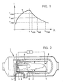
- Fig. 1 serves to illustrate the procedures for operating a heater shown in more detail in Fig. 2.
- the flame temperature T F is plotted against the air ratio ⁇ and the course of the curve a given there represents the empirically determined clear physical relationship between the flame temperature and air ratio at the firing temperature of a heater.
- This relationship between the flame temperature T F and the air ratio ⁇ is verified by the flame temperature T F measured in the combustion chamber in the method according to the invention.
- Is intended with ⁇ is designated for the air ratio of the target value, which is assigned to the Flammtemperaturkoordinate taking into account the physical unique relationship, a target value for the flame temperature T set.
- an empirically ascertainable minimum value for the air ratio ⁇ min and a corresponding empirically ascertainable maximum value for the air ratio ⁇ max are specified, these limit values ⁇ min and ⁇ max being given a corresponding maximum flame temperature value T max and minimum flame temperature value T min assigned.
- T max > T F > T min (corresponds to ⁇ min ⁇ ⁇ max ).
- T max maximum permissible flame temperature
- T F detected or measured flame temperature
- T min minimum permissible flame temperature
- ⁇ min minimum permissible air ratio
- ⁇ air ratio derived from detected or measured flame temperature
- T F ⁇ max maximum permissible air ratio.
- the heater is forced to shutdown or lock out. This can in the case of rain the air ratio ⁇ to the predetermined target value ⁇ , operation of the heater in an impermissible functional range is to be effectively avoided, as has been explained above.
- the control in the form of self-monitoring can be continuously checked in the operating method of the heater with control. When monitoring the area limits, the operating procedure enables the flame detector function to be implemented.
- the CO2 value in the exhaust gas of the heater which is clearly related to the air ratio, can be kept constant within narrow limits, so that one obtains a low-pollutant, but stable operation of the heater.
- a preferred embodiment of a heater designed according to the invention is explained with reference to FIG. 2.
- the heater as a whole is labeled 1.
- a combustion chamber 2 is provided in the heater 1.
- a so-called evaporation burner is illustrated as the burner 3, which has a nonwoven material 4, which serves to evaporate the fuel, such as liquid fuel, supplied via a fuel supply device 5.
- Combustion air is introduced into the combustion chamber 2 from a combustion air supply device, not shown, via schematically illustrated openings 6, as indicated by arrows.
- a combustion air supply device not shown, via schematically illustrated openings 6, as indicated by arrows.
- the flame curve for full-load operation is shown in solid lines and the flame curve for partial-load operation in broken lines.
- a total of 8 denotes a flame temperature detection device which is arranged in the flame area of the combustion chamber 2 in such a way that the temperature of the respective flame is always reliably and unambiguously detected regardless of the operating load of the heater, ie independently of full-load operation or part-load operation, for example.
- a device 9 shown schematically in block form, for determining the air ratio, which is designated by ⁇ .
- a spatially integrating sensor 10 is shown as flame temperature detection device 8, which sensor can be formed, for example, by a resistance thermometer. This spatially integrating sensor 10 starts from the flame root in the combustion chamber 2 and then extends in the direction of the burnout end of the flame.
- thermocouple An alternative embodiment of the flame temperature detection device 8, which is formed by a point-acting sensor 11, which can be, for example, a thermocouple, is illustrated with broken lines.
- This selective sensor 11 protrudes into the combustion chamber 2 in such a way that it is located in the combustion chamber 2 near the end of the burnout length of the flame.
- the method for operating a heater described in accordance with the invention is generally also suitable for stationary heating systems and not only for vehicle heaters.
Abstract
Description
Die Erfindung befaßt sich mit einem Verfahren zum Betreiben eines Heizgeräts, insbesondere eines Fahrzeugzusatzheizgeräts, bei dem einem Brenner Brennluft und Brennstoff zugeführt werden, und in einer Brennkammer eine Flamme erzeugt wird, sowie mit einem Heizgerät, insbesondere einem Fahrzeugzusatzheizgerät, das einen Brenner in einer Brennkammer, eine Brennstoffzufuhreinrichtung und eine Brennluftzufuhreinrichtung hat.The invention relates to a method for operating a heater, in particular a vehicle auxiliary heater, in which combustion air and fuel are supplied to a burner and a flame is generated in a combustion chamber, and to a heater, in particular a vehicle auxiliary heater, which has a burner in a combustion chamber , has a fuel supply device and a combustion air supply device.
Beim Verfahren zum Betreiben eines solchen Heizgeräts und bei dem Heizgerät selbst ergeben sich bisher im Hinblick auf eine stabile schadstoffarme Verbrennung Schwierigkeiten. Dies ist darauf zurückzuführen, daß die Verbrennung beispielsweise vom Differenzdruck zwischen dem Brennlufteintritt und dem Abgasaustritt, der sich durch Wind oder Fahrtwind bei einer Fahrzeugzusatzheizung ändern kann, von sich ändernden Widerständen im Ansaug- bzw. Abgassystem, von sich ändernden Höhenlagen, einer ungenügenden Brennstoffversorgung oder den Temperatureinflüssen oder dergleichen abhängig ist. Als Folge hiervon können ein erhöhter Schadstoffausstoß, ein Verrußen bzw. Verkoken der Brennkammer, des Wärmeübertragers und der vom Abgas durchströmten Einrichtungen, ein Rückbrennen oder dergleichen auftreten. Hierdurch bedingt kann es sogar passieren, daß das Heizgerät zerstört wird oder in Brand gerät, wodurch die Fahrzeugsicherheit beim Einbau eines derartigen Fahrzeugzusatzheizgeräts beeinträchtigt wird.In the method for operating such a heater and in the heater itself, difficulties have arisen with regard to stable, low-pollutant combustion. This is due to the fact that the combustion, for example, from the differential pressure between the combustion air inlet and the exhaust gas outlet, which can change due to wind or wind in a vehicle auxiliary heater, from changing resistances in the intake or exhaust system, from changing altitude, an insufficient fuel supply or is dependent on temperature influences or the like. As a result, increased pollutant emissions, sooting or coking of the combustion chamber, the heat exchanger and the devices through which the exhaust gas flows, back-burning or the like can occur. As a result, it can even happen that the heater is destroyed or catches fire, which affects vehicle safety when installing such a vehicle auxiliary heater.
Die Erfindung zielt darauf ab, unter Überwindung der zuvor geschilderten Schwierigkeiten ein Verfahren zum Betreiben eines Heizgeräts, insbesondere eines Fahrzeugheizgeräts der gattungsgemäßen Art sowie ein entsprechend ausgelegtes Heizgerät bereitzustellen, bei denen auf einfache Weise eine stabile und schadstoffarme Verbrennung zuverlässig gewährleistet wird.The invention aims to provide a method for operating a heater, in particular a vehicle heater of the generic type and a correspondingly designed heater, in which a stable and low-pollutant combustion is reliably guaranteed in a simple manner while overcoming the difficulties described above.
In verfahrenstechnischer Hinsicht wird bei einem Verfahren zum Betreiben eines Heizgeräts, insbesondere eines Fahrzeugzusatzheizgeräts, bei dem einem Brenner Brennluft und Brennstoff zugeführt werden und in einer Brennkammer eine Flamme erzeugt wird, derart vorgegangen, daß das Luftverhältnis, das allgemein in der Technik mit λ bezeichnet wird, auf der Basis der in der Brennkammer gemessenen Flammtemperatur ermittelt wird.From a procedural point of view, a method for operating a heater, in particular a vehicle auxiliary heater, in which combustion air and fuel are supplied to a burner and a flame is generated in a combustion chamber, is carried out in such a way that the air ratio, which is generally referred to in the art as λ , is determined on the basis of the flame temperature measured in the combustion chamber.
Das Verfahren nach der Erfindung nutzt den Umstand, daß bei einer Verbrennung in einem solchen Heizgerät ein eindeutiger physikalischer Zusammenhang zwischen dem Luftverhältnis λ und der adiabaten Verbrennungstemperatur, d.h. der Flammtemperatur, besteht. Beim erfindungsgemäßen Verfahren wird somit die Flammtemperatur erfaßt bzw. gemessen und hieraus unter Berücksichtigung des vorgegebenen eindeutigen physikalischen Zusammenhangs das entsprechende Luftverhältnis λ ermittelt, das einen Aufschluß über das Verhältnis von zugeführter Brennluftmenge und zugeführter Brennstoffmenge gibt. Wenn dieses Luftverhältnis λ innerhalb vorbestimmter Grenzwerte gehalten wird, läßt sich eine stabile und schadstoffarme Verbrennung gewährleisten. Bei einer derartigen Verfahrensweise nach der Erfindung werden die die Verbrennung in der Brennkammer beeinflußenden Störgrößen, wie Differenzdruck zwischen Lufteintritt und Abgasaustritt, variable Widerstände in den Ansaug- bzw. Abgassystemen, Temperatureinflüsse und dergleichen hinsichtlich den Einflüssen auf das Brennverhalten des Heizgeräts direkt oder indirekt durch die Messung der Flammtemperatur berücksichtigt, so daß sich in wirksamer Weise ein erhöhter Schadstoffausstoß und Heizgerätedefekte vermeiden lassen.The method according to the invention makes use of the fact that when a combustion occurs in such a heater, there is a clear physical relationship between the air ratio λ and the adiabatic combustion temperature, ie the flame temperature. In the method according to the invention, the flame temperature is thus detected and measured, and the corresponding air ratio λ is determined from this, taking into account the predetermined clear physical relationship, which provides information about the ratio of the amount of combustion air supplied and the amount of fuel supplied. If this air ratio λ is kept within predetermined limit values, stable and low-pollution combustion can be ensured. In such a procedure according to the invention, the disturbance variables influencing the combustion in the combustion chamber, such as differential pressure between the air inlet and exhaust gas outlet, variable resistances in the intake and exhaust systems, temperature influences and the like with regard to the influences on the combustion behavior of the heater taken into account directly or indirectly by measuring the flame temperature, so that increased pollutant emissions and heater defects can be effectively avoided.
Gemäß einer vorteilhaften Ausgestaltungsform des Verfahrens zum Betreiben eines Heizgeräts nach der Erfindung wird das Luftverhältnis λ auf einen vorbestimmten Sollwert dadurch geregelt, daß nach Maßgabe der ermittelten Flammtemperatur die Brennluft- und/oder Brennstoffzufuhr so verändert wird, bis die Flammtemperatur einen den vorbestimmten Sollwert für das Luftverhältnis zugeordneten Sollwert für die Flammtemperatur erreicht. Bei einer derartigen Auslegung des Verfahrens nach der Erfindung wird das Luftverhältnis λ über die Flammtemperatur auf einen vorbestimmten Sollwert geregelt, der sich im vorhinein geräteabhängig derart bestimmen läßt, daß unter allen Betriebsbedingungen des Heizgeräts eine möglichst stabile und schadstoffarme Verbrennung gewährleistet wird.According to an advantageous embodiment of the method for operating a heater according to the invention, the air ratio λ is regulated to a predetermined setpoint by changing the combustion air and / or fuel supply in accordance with the determined flame temperature until the flame temperature reaches a predetermined setpoint for the Air ratio assigned setpoint for the flame temperature reached. In such a design of the method according to the invention, the air ratio λ is regulated via the flame temperature to a predetermined setpoint, which can be determined in advance in a device-dependent manner in such a way that combustion which is as stable and low-pollutant as possible is guaranteed under all operating conditions of the heater.
Im Speziellen wird die Regelung bei einem Luftverhältnis λ von größer 1 dieses Luftverhältnis auf den Sollwert dadurch geregelt, daß bei einer über dem Sollwert für die Flammtemperatur gemessenen Flammtemperatur die zugeführte Brennluftmenge erhöht oder die zugeführte Brennstoffmenge gesenkt wird und bei einer unter dem Sollwert für die Flammtemperatur gemessenen Flammtemperatur die zugeführte Brennluftmenge gesenkt und die zugeführte Brennstoffmenge erhöht wird. Bei dieser Verfahrensweise wird durch die entsprechende Beeinflussung der zugeführten Brennluftmenge oder der zugeführten Brennstoffmenge die Verbrennung im Heizgerät derart beeinflußt, daß die Verbrennung wieder zu dem vorbestimmten Luftverhältnis gemäß dem vorgegebenen Sollwert hierfür zurückgeführt wird.In particular, the control is regulated at an air ratio λ of greater than 1 of this air ratio to the setpoint value in that the quantity of combustion air supplied is increased or the quantity of fuel supplied is increased at a flame temperature measured above the setpoint for the flame temperature and at a value below the setpoint for the flame temperature measured flame temperature, the quantity of combustion air supplied is reduced and the quantity of fuel supplied is increased. In this procedure, the combustion in the heater is influenced by the corresponding influencing of the quantity of combustion air supplied or the quantity of fuel supplied in such a way that the combustion is returned to the predetermined air ratio in accordance with the predetermined desired value for this purpose.
Gemäß einer weiteren Ausführungsvariante des Verfahrens nach der Erfindung wird eine Prüfung vorgenommen, ob innerhalb einer vorbestimmten Zeitdauer die erfaßte Flammtemperatur die folgende Bedingung erfüllt:
Tmax > TF > Tmin (entspricht λ min < λ < λmax)
wobei Tmax die maximal zulässige Flammtemperatur, TF die erfaßte Flammtemperatur, Tmin die minimal zulässige Flammtemperatur, λmin das zulässige minimale Luftverhältnis, λ das über die Flammtemperatur TF ermittelte Luftverhältnis und λmax das maximal zulässige Luftverhältnis bedeutet.According to a further embodiment variant of the method according to the invention, a check is made as to whether within a predetermined period of time the detected flame temperature meets the following condition:
T max > T F > T min (corresponds to λ min <λ <λ max )
where T max the maximum permissible flame temperature, T F the detected flame temperature, T min the minimum permissible flame temperature, λ min the permissible minimum air ratio, λ the air ratio determined via the flame temperature T F and λ max the maximum permissible air ratio.
Wenn diese vorstehend genannte Bedingung innerhalb des vorbestimmten Zeitraums nicht erfüllt wird, so wird das Heizgerät abgeschaltet. Wenn diese Verfahrensweise beim Verfahren zum Betreiben des Heizgeräts ohne eine Regelung auf den vorbestimmten Sollwert des Luftverhältnisses λ angewandt wird, so ermöglicht das erfindungsgemäße Betriebsverfahren eine Flammüberwachung ohne die zusätzliche Verwendung eines Flammwächters, da nämlich bei der Nichterfüllung der vorstehend genannten Bedingung innerhalb des vorbestimmten Zeitraumes durch die Temperaturerfassung der Flammtemperatur erkannt wird, daß sich in der Brennkammer des Heizgeräts keine Flamme ausgebildet hat, so daß in Abhängigkeit hiervon eine Zwangsabschaltung bzw. Störabschaltung des Heizgeräts vorgenommen wird. Durch die Überwachung der Bereichsgrenzen wird bei der Steuerung bzw. Regelung zugleich die Flammwächterfunktion mit übernommen. Wenn diese vorstehend genannte Bedingung bei der Verfahrensführung mit Regelung des Luftverhältnisses auf seinen vorbestimmten Sollwert nicht erfüllt wird, so läßt sich der Schluß ziehen, daß sich das Heizgerät, aus welchen Gründen auch immer, nicht stabil und schadstoffarm betreiben läßt, so daß zur Vermeidung von eventuellen möglichen Geräteschäden ebenfalls eine Zwangsabschaltung des Heizgeräts vorgenommen wird. Selbst wenn das Luftverhältnis λ im Bereich von kleiner 1 liegt, kann nach Maßgabe dieser vorstehend genannten Bedingung gewährleistet werden, daß nicht durch entsprechende Änderungen der zugeführten Brennluftmenge und/oder der zugeführten Brennstoffmenge das Heizgerät in einen unzulässigen Betriebsbereich kommt.If this condition mentioned above is not met within the predetermined period, the heater is switched off. If this procedure is used in the method for operating the heater without regulating the predetermined setpoint value of the air ratio λ, the operating method according to the invention enables flame monitoring without the additional use of a flame detector, namely if the above-mentioned condition is not met within the predetermined period of time the temperature detection of the flame temperature is recognized that no flame has formed in the combustion chamber of the heater, so that, depending on this, a forced shutdown or lockout of the heater is carried out. By monitoring the area limits, the flame monitor function is also taken over in the control. If this condition mentioned above is not met in the process control with regulation of the air ratio to its predetermined setpoint, it can be concluded that the heater, for whatever reason, cannot be operated stably and with low pollutants, so that to avoid any possible device damage is also a forced shutdown of the heater. Even if the air ratio λ is in the range of less than 1, this condition mentioned above can Ensure that the heater does not come into an impermissible operating range due to corresponding changes in the quantity of combustion air and / or the quantity of fuel supplied.
In gerätetechnischer Hinsicht zeichnet sich erfindungsgemäß ein Heizgerät, insbesondere ein Fahrzeugzusatzheizgerät, mit einem Brenner in einer Brennkammer, einer Brennluftzufuhreinrichtung und einer Brennstoffzufuhreinrichtung dadurch aus, daß eine Temperaturerfassungseinrichtung im Flammbereich der Brennkammer zur lastunabhängigen Erfassung der Flammtemperatur angeordnet ist, die mit einer Einrichtung zur Ermittlung des Luftverhältnisses verbunden ist. Die nach der Erfindung in vorrichtungstechnischer Hinsicht geschaffene Lösung läßt sich auf konstruktiv einfache Weise verwirklichen und es wird ein Heizgerät bereitgestellt, das zuverlässig schadstoffarm und stabil betreibbar ist und kostengünstig hergestellt werden kann.In terms of device technology, a heater, in particular a vehicle auxiliary heater, with a burner in a combustion chamber, a combustion air supply device and a fuel supply device is distinguished in that a temperature detection device is arranged in the flame region of the combustion chamber for load-independent detection of the flame temperature, which is provided with a device for determining the Air ratio is connected. The solution created according to the invention in terms of device technology can be implemented in a structurally simple manner and a heater is provided which can be operated reliably and with low pollutants and is stable and can be produced inexpensively.
Als Temperaturerfassungseinrichtung kann ein räumlich integrierender Sensor, wie ein Widerstandsthermometer, vorgesehen sein, der zweckmäßigerweise in der Brennkammer derart angeordnet ist, daß er von der Flammwurzel ausgeht und sich in den Flammbereich in der Brennkammer erstreckt.A spatially integrating sensor, such as a resistance thermometer, can be provided as the temperature detection device, which is expediently arranged in the combustion chamber in such a way that it starts from the flame root and extends into the flame region in the combustion chamber.
Alternativ kann als Temperaturerfassungseinrichtung ein punktuell wirkender Sensor, wie ein Thermoelement vorgesehen sein, der zweckmäßigerweise in der Nähe des Endes der Ausbrandlänge der Flamme in die Brennkammer ragt.Alternatively, a point-acting sensor, such as a thermocouple, can be provided as the temperature detection device, which expediently protrudes into the combustion chamber near the end of the burnout length of the flame.
Gemäß einer bevorzugten Ausbildungsform des Heizgeräts nach der Erfindung schaltet die Einrichtung zur Ermittlung des Luftverhältnisses das Heizgerät ab, wenn nach einer vorbestimmten Zeitdauer der durch die folgende Bedingung bestimmte Betriebsbereich nicht erreicht ist:
Tmax > TF > Tmin (entspricht λmin < λ < λmax)
wobei diese Größen die vorstehend im Zusammenhang mit dem erfindungsgemäßen Betriebsverfahren erläuterte Bedeutung haben.According to a preferred embodiment of the heater according to the invention, the device for determining the air ratio switches the heater off if after a predetermined period of time the operating range determined by the following condition has not been reached:
T max > T F > T min (corresponds to λ min <λ <λ max )
these variables have the meaning explained above in connection with the operating method according to the invention.
Bei einer solchen Auslegung des Heizgeräts übernimmt die Temperaturerfassungseinrichtung und die hiermit in Verbindung stehende Einrichtung zur Ermittlung des Luftverhältnisses zugleich die Funktion eines bisher üblichen Flammwächters, so daß dieser bisher als besonderes Bauteil ausgebildete Flammwächter entfallen kann. Zugleich wird aber auch sichergestellt, daß das Heizgerät auch dann abgeschaltet wird, wenn bei einer Regelung unter Veränderung der zugeführten Brennluft- und/oder Brennstoffmenge die Gefahr besteht, daß das Heizgerät in einen unzulässigen Betriebsbereich gelangen kann.With such a design of the heater, the temperature detection device and the associated device for determining the air ratio at the same time take over the function of a previously usual flame detector, so that this flame detector, which was previously a special component, can be omitted. At the same time, however, it is also ensured that the heater is also switched off when there is a risk that the heater may enter an inadmissible operating range when the amount of combustion air and / or fuel supplied is changed.
Die Erfindung wird nachstehend an Beispielen unter Bezugnahme auf die beigefügte Zeichnung näher erläutert. Darin zeigt:
- Fig. 1 ein Diagramm zur Verdeutlichung des Zusammenhangs von Flammtemperatur und Luftverhältnis, und
- Fig. 2 eine schematische Ansicht eines Heizgeräts gemäß einer bevorzugten Ausbildungsform nach der Erfindung.
- Fig. 1 is a diagram to illustrate the relationship between flame temperature and air ratio, and
- Fig. 2 is a schematic view of a heater according to a preferred embodiment of the invention.
Fig. 1 dient zur Verdeutlichung der Verfahrensweisen zum Betreiben eines in Fig. 2 näher dargestellten Heizgeräts. In Fig. 1 ist die Flammtemperatur TF über dem Luftverhältnis λ aufgetragen und der Verlauf des dort angegebenen Kurvenzugs a stellt den empirisch ermittelbaren eindeutigen physikalischen Zusammenhang zwischen Flammtemperatur und Luftverhältnis bei der Brenntemperatur eines Heizgeräts dar. Dieser Zusammenhang zwischen der Flammtemperatur TF und dem Luftverhältnis λ wird durch die in der Brennkammer gemessene Flammtemperatur TF beim erfindungsgemäßen Verfahren verifiziert. Mit λsoll ist der Soll-Wert für das Luftverhältnis bezeichnet, dem auf der Flammtemperaturkoordinate unter Berücksichtigung des physikalischen eindeutigen Zusammenhangs ein Soll-Wert für die Flammtemperatur Tsoll zugeordnet ist. Zur Erzielung einer schadstoffarmen und stabilen Verbrennung wird ein empirisch ermittelbarer Minimalwert für das Luftverhältnis λmin und ein entsprechend empirisch ermittelbarer Maximalwert für das Luftverhältnis λmax vorgegeben, wobei diesen Grenzwerten λmin und λmax ein entsprechender maximaler Flammtemperaturwert Tmax bzw. minimaler Flammtemperaturwert Tmin zugeordnet sind.Fig. 1 serves to illustrate the procedures for operating a heater shown in more detail in Fig. 2. In Fig. 1, the flame temperature T F is plotted against the air ratio λ and the course of the curve a given there represents the empirically determined clear physical relationship between the flame temperature and air ratio at the firing temperature of a heater. This relationship between the flame temperature T F and the air ratio λ is verified by the flame temperature T F measured in the combustion chamber in the method according to the invention. Is intended with λ is designated for the air ratio of the target value, which is assigned to the Flammtemperaturkoordinate taking into account the physical unique relationship, a target value for the flame temperature T set. To achieve a low-pollutant and stable combustion, an empirically ascertainable minimum value for the air ratio λ min and a corresponding empirically ascertainable maximum value for the air ratio λ max are specified, these limit values λ min and λ max being given a corresponding maximum flame temperature value T max and minimum flame temperature value T min assigned.
Zuerst wird die Verfahrensweise nach der Erfindung erläutert, wenn eine Regelung auf den Soll-Wert für das Luftverhältnis λsoll vorgenommen werden soll und hierbei ein Regelbereich von λ > 1 eingehalten wird. Wenn die nach der Erfindung gemessene Flammtemperatur TF größer als der Soll-Wert Tsoll ist, so wird entweder die zugeführte Brennluftmenge erhöht oder die zugeführte Brennstoffmenge vermindert, um das Luftverhältnis λ bis zur Erreichung des Soll-Wertes λsoll anzuheben. Wenn hingegen die gemessene Flammtemperatur TF niedriger als der Soll-Wert für die Flammtemperatur Tsoll ist, so wird entweder die dem Brenner zugeführte Brennluftmenge vermindert oder die dem Brenner zugeführte Brennstoffmenge erhöht, bis der Soll-Wert für das Luftverhältnis λsoll erreicht ist.First of all, the procedure according to the invention is explained when a regulation to the target value for the air ratio λ target is to be carried out and a control range of λ> 1 is maintained. If the measured according to the invention flame temperature T F is greater than the target value T set, either the supplied combustion air quantity is increased or decreased, the amount of fuel supplied to the air ratio λ to achieve the desired value to λ raise. In contrast, when the measured flame temperature T F lower than the target value for the flame temperature T set, then either fed to the burner combustion air amount is reduced or the power supplied to the burner fuel quantity increased to λ until the desired value for the air ratio is reached.
Wenn das Heizgerät in dem Bereich beim Diagramm nach Fig. 1 betrieben wird, bei dem gilt λ < 1, so wird dann, wenn die in der Brennkammer gemessene Flammtemperatur TF größer als der Soll-Wert für die Flammtemperatur Tsoll ist, eine Regelung in der Form vorgenommen, daß entweder die zugeführte Brennluftmenge erhöht oder die zugeführte Brennstoffmenge ver ringert wird, so daß das Luftverhältnis λ gemäß dem Diagramm nach Fig. 1 in Richtung des Soll-Werts für das Luftverhältnis λsoll verändert wird. Wenn die in der Brennkammer gemessene Flammtemperatur TF kleiner als der Soll-Wert für die Flammtemperatur Tsoll ist, so wird bei einer Veränderung der dem Brenner des Heizgeräts zugeführten Brennluftmenge und/oder Brennstoffmenge erreicht, daß sich die dann erhaltenen Werte für das Luftverhältnis λ immer weiter von dem vorgegebenen Soll-Wert für das Luftverhältnis λsoll wegbewegen. Daher ist in diesem Fall das Heizgerät abzuschalten.When the heater is operated in the area in the diagram according to Fig. 1, in which applies λ <1, then when the measured in the combustor flame temperature T F is greater than the target value for the flame temperature T set, is a scheme made in such a way that either the amount of combustion air supplied increases or the amount of fuel supplied ver is Ringert, so that the air ratio λ, according to the diagram of FIG. 1 in the direction of the target value for the air ratio λ is to be changed. Is intended when the measured in the combustor flame temperature T F is less than the target value for the flame temperature T, so with a change in the burner of the heater supplied combustion air quantity and / or quantity of fuel is achieved that the values are then obtained for the air ratio λ will continue to λ from the predetermined desired value for the air ratio to move away. Therefore, the heater must be switched off in this case.
Beim erfindungsgemäßen Verfahren zum Betreiben eines Heizgeräts werden in Weiterbildung die vorstehend erörterten Funktionsgrenzen überwacht, um wirksam eine Zwangsabschaltung des Heizgeräts zu bewirken und eine Beschädigung oder Zerstörung desselben zu verhindern. Daher wird beim erfindungsgemäßen Betriebsverfahren die den zulässigen Funktionsbereich definierende und nachstehend angegebene Bedingung überwacht und überprüft:
Tmax > TF > Tmin (entspricht λmin < λ < λmax).
Hierbei bedeutet:
Tmax = maximal zulässige Flammtemperatur,
TF = erfaßte oder gemessene Flammtemperatur,
Tmin = minimal zulässige Flammtemperatur,
λmin = minimal zulässiges Luftverhältnis,
λ = aus erfaßter oder gemessener Flammtemperatur TF abgeleitetes Luftverhältnis
λmax = maximal zulässiges Luftverhältnis.In the method according to the invention for operating a heater, the functional limits discussed above are monitored in a further development in order to effectively bring about a forced shutdown of the heater and to prevent damage or destruction thereof. Therefore, in the operating method according to the invention, the condition defining the permissible functional range and specified below is monitored and checked:
T max > T F > T min (corresponds to λ min <λ <λ max ).
Here means:
T max = maximum permissible flame temperature,
T F = detected or measured flame temperature,
T min = minimum permissible flame temperature,
λ min = minimum permissible air ratio,
λ = air ratio derived from detected or measured flame temperature T F
λ max = maximum permissible air ratio.
Wenn beim Betrieb des Heizgeräts diese vorstehend genannte Bedingung innerhalb einer vorgegebenen Zeitspanne nicht erfüllt wird, so erfolgt eine Zwangsabschaltung bzw. Störabschaltung des Heizgeräts. Hierdurch kann im Falle einer Rege lung des Luftverhältnisses λ auf den vorbestimmten Soll-Wert λsoll wirksam ein Betreiben des Heizgeräts in einem unzulässigen Funktionsbereich vermieden werden, wie dies vorangehend erläutert worden ist. Somit kann bei dem Betriebsverfahren des Heizgeräts mit Regelung ständig die Regelung in Form einer Eigenüberwachung überprüft werden. Bei Überwachung der Bereichsgrenzen ermöglicht das Betriebsverfahren die Verwirklichung der Flammwächterfunktion. Wenn hingegen beim erfindungsgemäßen Betriebsverfahren zur Ermittlung des Luftverhältnisses lediglich die Flammtemperatur TF gemessen wird, so wird durch die Überprüfung und die Überwachung dieser vorstehend genannten Bedingung die Aufgabe eines Flammwächters bei Heizgeräten dieser Art verwirklicht, so daß man einen in bisher üblicherweise vorgesehenen gesonderten Flammwächter weglassen kann, der bei den bisherigen Ausführungsformen in den Flammbereich der Brennkammer ragte und hierdurch die Brennbedingungen in der Brennkammer veränderte.If, during operation of the heater, the above-mentioned condition is not met within a predetermined period of time, the heater is forced to shutdown or lock out. This can in the case of rain the air ratio λ to the predetermined target value λ , operation of the heater in an impermissible functional range is to be effectively avoided, as has been explained above. Thus, the control in the form of self-monitoring can be continuously checked in the operating method of the heater with control. When monitoring the area limits, the operating procedure enables the flame detector function to be implemented. If, on the other hand, only the flame temperature T F is measured in the operating method according to the invention for determining the air ratio, then by checking and monitoring this condition mentioned above, the task of a flame detector in heaters of this type is realized, so that a separate flame detector that was previously provided is omitted can, which in the previous embodiments protruded into the flame area of the combustion chamber and thereby changed the combustion conditions in the combustion chamber.
Mit dem erfindungsgemäßen Regelverfahren kann der CO₂-Wert im Abgas des Heizgeräts, der in eindeutigem Zusammenhang mit dem Luftverhältnis steht, in engen Grenzen konstant gehalten werden, so daß man einen schadstoffarmen, aber dennoch stabilen Betrieb des Heizgeräts erhält.With the control method according to the invention, the CO₂ value in the exhaust gas of the heater, which is clearly related to the air ratio, can be kept constant within narrow limits, so that one obtains a low-pollutant, but stable operation of the heater.
Unter Bezugnahme auf Fig. 2 wird ein bevorzugtes Ausführungsbeispiel eines nach der Erfindung ausgelegten Heizgeräts erläutert. Das Heizgerät insgesamt ist mit 1 bezeichnet. Im Heizgerät 1 ist eine Brennkammer 2 vorgesehen. Als Brenner 3 ist beim dargestellten Beispiel des Heizgeräts 1 ein sogenannter Verdampfungsbrenner verdeutlicht, der ein Vliesmaterial 4 hat, das zur Verdampfung des über eine Brennstoffzufuhreinrichtung 5 zugeführten Brennstoffs, wie flüssigen Brennstoffs, dient. Über schematisch dargestellte Öffnungen 6 wird - wie mit Pfeilen angedeutet - Brennluft von einer nicht näher dargestellten Brennluftzufuhreinrichtung in die Brennkammer 2 eingeleitet. Im Brennbetrieb des Heizgeräts 1 bildet sich in der Brenn kammer lastabhängig eine entsprechende Flamme aus. In durchgezogenen Linien ist der Flammverlauf für den Vollastbetrieb und in gebrochener Linie der Flammverlauf für den Teillastbetrieb verdeutlicht. Insgesamt mit 8 ist eine Flammtemperaturerfassungseinrichtung bezeichnet, die im Flammbereich der Brennkammer 2 derart angeordnet ist, daß unabhängig von der Betriebslast des Heizgeräts, d.h. unabhängig vom Vollastbetrieb oder Teillastbetrieb beispielsweise, immer zuverlässig und eindeutig die Temperatur der jeweiligen Flamme erfaßt wird. Mit dieser Flammtemperaturerfassungseinrichtung 8 ist eine schematisch in Blockform dargestellte Einrichtung 9 zur Ermittlung des Luftverhältnisses verbunden, das mit λ bezeichnet ist.A preferred embodiment of a heater designed according to the invention is explained with reference to FIG. 2. The heater as a whole is labeled 1. A
In durchgezogener Linie ist in Fig. 2 als Flammtemperaturerfassungseinrichtung 8 ein räumlich integrierender Sensor 10 dargestellt, der beispielsweise von einem Widerstandsthermometer gebildet werden kann. Dieser räumlich integrierende Sensor 10 geht von der Flammwurzel in der Brennkammer 2 aus und erstreckt sich dann in Richtung des Ausbrandsendes der Flamme.In a solid line in FIG. 2, a spatially integrating
Mit gebrochenen Linien ist eine alternative Ausführungsform der Flammtemperaturerfassungseinrichtung 8 verdeutlicht, die von einem punktuell wirkenden Sensor 11 gebildet wird, der beispielsweise ein Thermoelement sein kann. Dieser punktuell wirkende Sensor 11 ragt in die Brennkammer 2 derart, daß er sich in der Nähe des Endes der Ausbrandlänge der Flamme in der Brennkammer 2 befindet.An alternative embodiment of the flame
Mit Hilfe einer derartigen in der Brennkammer 2 vorgesehenen Flammtemperaturerfassungseinrichtung 8 kann dann in Verbindung mit der Einrichtung 9 zur Ermittlung des Luftverhältnisses λ die jeweilige vorangehend erläuterte Verfahrensweise zum Betreiben des Heizgeräts 1 verwirklicht werden. Die näheren regelungstechnischen Einzelheiten hierfür geeigneter Regel einrichtungen wird der Fachmann in geeigneter Weise bedarfsabhängig wählen und auslegen. Daher erübrigt sich ein näheres Eingehen auf Einzelheiten von konkreten Ausbildungsformen der Regeleinheiten.With the aid of such a flame
Das nach der Erfindung beschriebene Verfahren zum Betreiben eines Heizgeräts ist ganz allgemein gesehen auch für stationäre Heizungsanlagen und nicht nur für Fahrzeugheizungen geeignet.The method for operating a heater described in accordance with the invention is generally also suitable for stationary heating systems and not only for vehicle heaters.
- a Kurvenzug in Fig. 1. der die eindeutige physikalische Zuordnung von Flammtemperatur und Luftverhältnis wiedergibt,a curve in FIG. 1, which shows the clear physical assignment of flame temperature and air ratio,
- TF Flammtemperatur gemessenT F flame temperature measured
- Tmin minimal zulässige FlammtemperaturT min minimum permissible flame temperature
- Tmax maximal zulässige FlammtemperaturT max maximum permissible flame temperature
- Tsoll vorgegebener Soll-Wert für die Flammtemperatur TF T target is the predetermined target value for the flame temperature T F
- λ Luftverhältnisλ air ratio
- λmin minimal zulässiges Luftverhältnisλ min minimum permissible air ratio
- λmax maximal zulässiges Luftverhältnisλ max maximum permissible air ratio
- λsoll Soll-Wert für das Luftverhältnisλ should be the target value for the air ratio
- 1 Heizgerät insgesamt1 heater in total
- 2 Brennkammer2 combustion chamber
- 3 Brenner3 burners
- 4 Vliesmaterial4 non-woven material
- 5 Brennstoffzufuhreinrichtung5 fuel supply device
- 6 Öffnungen für Brennluftzufuhr6 openings for combustion air supply
- 8 Flammtemperaturerfassungseinrichtung8 flame temperature detection device
- 9 Einrichtung zur Ermittlung des Luftverhältnisses9 Device for determining the air ratio
- 10 räumlich integrierender Sensor10 spatially integrating sensor
- 11 punktuell wirkender Sensor11 selective sensor
Claims (10)
Tmax > TF > Tmin entspricht λmin < λ < λmax
wobei Tmax die maximal zulässige Flammtemperatur, TF die erfaßte oder gemessene Flammtemperatur, Tmin die minimal zulässige Flammtemperatur, λmin das minimal zulässige Luftverhältnis, λ das der gemessenen Flammtemperatur (TF) entsprechende Luftverhältnis und (λmax) das maximal zulässige Luftverhältnis bezeichnet, und daß bei Nichterfüllung der Bedingung das Heizgerät abgeschaltet wird.4. The method according to claim 1 or one of claims 2 or 3, characterized in that it is checked whether the detected flame temperature (T F ) meets the following condition within a predetermined period:
T max > T F > T min corresponds to λ min <λ <λ max
where T max the maximum allowable flame temperature, T F the detected or measured flame temperature, T min the minimum allowable flame temperature, λ min the minimum allowable air ratio, λ the air ratio corresponding to the measured flame temperature (T F ) and (λ max ) the maximum allowable air ratio designated, and that if the condition is not met, the heater is switched off.
Tmax > TF > Tmin entspricht λmin < λ < λmax
wobei Tmax die maximal zulässige Flammtemperatur, TF die erfaßte oder gemessene Flammtemperatur, Tmin die minimal zulässige Flammtemperatur, λmin das minimal zulässige Luftverhältnis, λ das der gemessenen Flammtemperatur (TF) entsprechende Luftverhältnis und λmax das maximal zulässige Luftverhältnis bezeichnet, und daß bei Nichterfüllung der Bedingung das Heizgerät abgeschaltet wird.10. Heater according to one of claims 5 to 9, characterized in that the device (9) for determining the air ratio (λ) switches off the heater if after a predetermined period of time the operating range determined by the following condition has not been reached:
T max > T F > T min corresponds to λ min <λ <λ max
where T max the maximum allowable flame temperature, T F the detected or measured flame temperature, T min the minimum allowable flame temperature, λ min the minimum allowable air ratio, λ the air ratio corresponding to the measured flame temperature (T F ) and λ max the maximum allowable air ratio, and that if the condition is not met, the heater is switched off.
Applications Claiming Priority (2)
| Application Number | Priority Date | Filing Date | Title |
|---|---|---|---|
| DE3807388A DE3807388A1 (en) | 1988-03-07 | 1988-03-07 | METHOD FOR OPERATING A HEATING DEVICE AND HEATING DEVICE |
| DE3807388 | 1988-03-07 |
Publications (2)
| Publication Number | Publication Date |
|---|---|
| EP0331918A2 true EP0331918A2 (en) | 1989-09-13 |
| EP0331918A3 EP0331918A3 (en) | 1990-09-05 |
Family
ID=6349036
Family Applications (1)
| Application Number | Title | Priority Date | Filing Date |
|---|---|---|---|
| EP19890102180 Withdrawn EP0331918A3 (en) | 1988-03-07 | 1989-02-09 | Actuating method for a heating apparatus, and heating apparatus |
Country Status (3)
| Country | Link |
|---|---|
| EP (1) | EP0331918A3 (en) |
| JP (1) | JPH01262214A (en) |
| DE (1) | DE3807388A1 (en) |
Cited By (8)
| Publication number | Priority date | Publication date | Assignee | Title |
|---|---|---|---|---|
| WO1996021127A1 (en) * | 1994-12-30 | 1996-07-11 | Firma J. Eberspächer | Vehicle heater |
| US5616021A (en) * | 1994-09-19 | 1997-04-01 | Nippon Soken Inc. | Fuel burning heater |
| WO2004015333A2 (en) * | 2002-08-05 | 2004-02-19 | Merloni Termosanitari S.P.A. | Combustion control system with virtual lambda sensor |
| EP1612480A2 (en) | 2004-06-28 | 2006-01-04 | J. Eberspächer GmbH & Co. KG | Vaporizing Burner |
| WO2006000367A1 (en) * | 2004-06-23 | 2006-01-05 | Ebm-Papst Landshut Gmbh | Method for adjusting the excess air coefficient on a firing apparatus, and firing apparatus |
| DE102006015771A1 (en) * | 2006-04-04 | 2007-10-11 | J. Eberspächer GmbH & Co. KG | Fuel driven vehicle heater operating method, involves changing fuel supply amount for combustion in burner region, if temperature value deviates from reference temperature value, such that deviation decreases |
| WO2008058408A2 (en) * | 2006-11-17 | 2008-05-22 | Toby Ag | Method for controlling an evaporator burner |
| EP4174375A1 (en) * | 2021-10-27 | 2023-05-03 | Vaillant GmbH | Method for validating a signal of a device for flame monitoring of a heater, computer program, storage medium, control device, heater and use of a temperature sensor |
Families Citing this family (8)
| Publication number | Priority date | Publication date | Assignee | Title |
|---|---|---|---|---|
| DE4141116C1 (en) * | 1991-12-13 | 1993-04-08 | Webasto Ag Fahrzeugtechnik, 8035 Stockdorf, De | Operating burner receiving exhaust gas of IC engine - regenerating particle filter installation producing flame in variable manner |
| US5722588A (en) * | 1994-04-13 | 1998-03-03 | Nippon Soken Inc. | Combustion heater |
| US5617995A (en) * | 1994-04-22 | 1997-04-08 | Nippon Soken Inc | Combustion heater |
| DE4433210C2 (en) * | 1994-09-17 | 1999-07-01 | Webasto Thermosysteme Gmbh | Additional vehicle heater |
| DE19636430C2 (en) * | 1996-09-07 | 2002-02-14 | Webasto Thermosysteme Gmbh | Method and device for operating an engine-independent vehicle heater |
| DE29924803U1 (en) * | 1999-10-23 | 2005-12-01 | Webasto Ag | Burner-powered heater has combustion chamber and flame monitor containing thermoelement that protrudes with measurement point at least into edge region of flame in burner |
| DE102016122821B3 (en) * | 2016-11-25 | 2018-02-08 | Webasto SE | A fuel powered vehicle heater and method of operating a fuel powered vehicle heater |
| DE102017119077A1 (en) * | 2017-08-21 | 2019-02-21 | Eberspächer Climate Control Systems GmbH & Co. KG | vehicle heater |
Citations (5)
| Publication number | Priority date | Publication date | Assignee | Title |
|---|---|---|---|---|
| US4033712A (en) * | 1976-02-26 | 1977-07-05 | Edmund D. Hollon | Fuel supply systems |
| US4480986A (en) * | 1983-09-14 | 1984-11-06 | Sea-Labs, Inc. | Liquid fuel vaporizing burner |
| JPS61197914A (en) * | 1985-02-27 | 1986-09-02 | Matsushita Electric Ind Co Ltd | Control circuit for burner |
| GB2191022A (en) * | 1986-05-27 | 1987-12-02 | Rinnai Kk | A fluid heating apparatus |
| JPS6349624A (en) * | 1986-08-18 | 1988-03-02 | Matsushita Electric Ind Co Ltd | Combustion device |
-
1988
- 1988-03-07 DE DE3807388A patent/DE3807388A1/en not_active Withdrawn
-
1989
- 1989-02-09 EP EP19890102180 patent/EP0331918A3/en not_active Withdrawn
- 1989-03-03 JP JP1051846A patent/JPH01262214A/en active Pending
Patent Citations (5)
| Publication number | Priority date | Publication date | Assignee | Title |
|---|---|---|---|---|
| US4033712A (en) * | 1976-02-26 | 1977-07-05 | Edmund D. Hollon | Fuel supply systems |
| US4480986A (en) * | 1983-09-14 | 1984-11-06 | Sea-Labs, Inc. | Liquid fuel vaporizing burner |
| JPS61197914A (en) * | 1985-02-27 | 1986-09-02 | Matsushita Electric Ind Co Ltd | Control circuit for burner |
| GB2191022A (en) * | 1986-05-27 | 1987-12-02 | Rinnai Kk | A fluid heating apparatus |
| JPS6349624A (en) * | 1986-08-18 | 1988-03-02 | Matsushita Electric Ind Co Ltd | Combustion device |
Non-Patent Citations (2)
| Title |
|---|
| PATENT ABSTRACTS OF JAPAN vol. 11, no. 25 (M-556)(2472) 23 Januar 1987, & JP-A-61 197914 (MATSUSHITA ELECTRIC) 02 September 1986, * |
| PATENT ABSTRACTS OF JAPAN vol. 12, no. 267 (M-722)(3114) 26 Juli 1988, & JP-A-63 49624 (MATSUSHITA ELECTRIC) 02 März 1988, * |
Cited By (13)
| Publication number | Priority date | Publication date | Assignee | Title |
|---|---|---|---|---|
| US5616021A (en) * | 1994-09-19 | 1997-04-01 | Nippon Soken Inc. | Fuel burning heater |
| WO1996021127A1 (en) * | 1994-12-30 | 1996-07-11 | Firma J. Eberspächer | Vehicle heater |
| WO2004015333A2 (en) * | 2002-08-05 | 2004-02-19 | Merloni Termosanitari S.P.A. | Combustion control system with virtual lambda sensor |
| WO2004015333A3 (en) * | 2002-08-05 | 2004-06-03 | Merloni Termosanitari Spa | Combustion control system with virtual lambda sensor |
| CN100570218C (en) * | 2002-08-05 | 2009-12-16 | 默洛尼卫生洁具有限公司 | Fuel Control System with virtual exhaust gas oxygensensor |
| US7922481B2 (en) | 2004-06-23 | 2011-04-12 | EBM—Papst Landshut GmbH | Method for setting the air ratio on a firing device and a firing device |
| WO2006000367A1 (en) * | 2004-06-23 | 2006-01-05 | Ebm-Papst Landshut Gmbh | Method for adjusting the excess air coefficient on a firing apparatus, and firing apparatus |
| EP1612480A3 (en) * | 2004-06-28 | 2008-12-10 | J. Eberspächer GmbH & Co. KG | Vaporizing Burner |
| EP1612480A2 (en) | 2004-06-28 | 2006-01-04 | J. Eberspächer GmbH & Co. KG | Vaporizing Burner |
| DE102006015771A1 (en) * | 2006-04-04 | 2007-10-11 | J. Eberspächer GmbH & Co. KG | Fuel driven vehicle heater operating method, involves changing fuel supply amount for combustion in burner region, if temperature value deviates from reference temperature value, such that deviation decreases |
| WO2008058408A3 (en) * | 2006-11-17 | 2008-07-17 | Toby Ag | Method for controlling an evaporator burner |
| WO2008058408A2 (en) * | 2006-11-17 | 2008-05-22 | Toby Ag | Method for controlling an evaporator burner |
| EP4174375A1 (en) * | 2021-10-27 | 2023-05-03 | Vaillant GmbH | Method for validating a signal of a device for flame monitoring of a heater, computer program, storage medium, control device, heater and use of a temperature sensor |
Also Published As
| Publication number | Publication date |
|---|---|
| DE3807388A1 (en) | 1989-09-21 |
| EP0331918A3 (en) | 1990-09-05 |
| JPH01262214A (en) | 1989-10-19 |
Similar Documents
| Publication | Publication Date | Title |
|---|---|---|
| EP0331918A2 (en) | Actuating method for a heating apparatus, and heating apparatus | |
| EP2594848B1 (en) | Method for controlling a firing device and firing device | |
| EP1621811B1 (en) | Operating Method for a Combustion Apparatus | |
| DE4417199C2 (en) | Device for controlling gas turbines | |
| EP2005066B1 (en) | Method for starting a firing device in unknown general conditions | |
| DE2656840A1 (en) | METHOD AND DEVICE FOR REGULATING THE ENERGY SUPPLY TO A HEATING DEVICE | |
| EP0833106B1 (en) | Method and device for operation optimisation of a gas burner | |
| EP1331444B1 (en) | Method for regulating a gas burner | |
| EP2017531B1 (en) | Method for monitoring an ionisation electrode signal in burners | |
| EP3593047B1 (en) | Method for identifying the type of fuel gas during the starting operation of a fuel-gas-operated heating device and fuel-gas-operated heating device | |
| DE60021779T2 (en) | A modulating burner system for preventing the use of non-commissioned devices and testing the health of inoperative devices | |
| EP0615095B1 (en) | Burner controller | |
| DE19734574B4 (en) | Method and device for controlling a burner, in particular a fully premixing gas burner | |
| DE19921045B4 (en) | Burner for combustion of liquid and / or gaseous fuels in combustion plants | |
| EP1519113A2 (en) | Method for adapting the heating power of a blower-supported heater to the individual pressure losses of a fresh air/exhaust gas pipe system | |
| EP3182007B1 (en) | Heating device system and method with a heating device system | |
| EP0614051B1 (en) | Burner automat | |
| DE3114942A1 (en) | CONTROL DEVICE FOR THE GAS-FIRED BOILER OF A HOT WATER HEATING SYSTEM | |
| EP0321858A2 (en) | Combustion apparatus | |
| EP1752708B1 (en) | Method for flame detection in a vehicle heater | |
| DE4331048A1 (en) | Method and device for operating an over-stoichiometric premixing gas burner | |
| DE102004063992B4 (en) | Regulating and controlling process for firing apparatus involves using characteristic curve showing value range for setpoint temperature in accordance with two parameters | |
| EP4060235A1 (en) | Method for operating a heater with an electronic gas / air connection | |
| DE102022122811A1 (en) | Method for operating a heater, computer program, control and control device, fuel flow regulator and heater | |
| EP1260766B1 (en) | Method for adapting a fired heater to the air/flue gas stack |
Legal Events
| Date | Code | Title | Description |
|---|---|---|---|
| PUAI | Public reference made under article 153(3) epc to a published international application that has entered the european phase |
Free format text: ORIGINAL CODE: 0009012 |
|
| AK | Designated contracting states |
Kind code of ref document: A2 Designated state(s): DE FR GB SE |
|
| PUAL | Search report despatched |
Free format text: ORIGINAL CODE: 0009013 |
|
| AK | Designated contracting states |
Kind code of ref document: A3 Designated state(s): DE FR GB SE |
|
| STAA | Information on the status of an ep patent application or granted ep patent |
Free format text: STATUS: THE APPLICATION IS DEEMED TO BE WITHDRAWN |
|
| 18D | Application deemed to be withdrawn |
Effective date: 19910306 |