EP0331618A2 - Procédé pour la fabrication d'un profilé en acier, son application et profilé - Google Patents
Procédé pour la fabrication d'un profilé en acier, son application et profilé Download PDFInfo
- Publication number
- EP0331618A2 EP0331618A2 EP19890730048 EP89730048A EP0331618A2 EP 0331618 A2 EP0331618 A2 EP 0331618A2 EP 19890730048 EP19890730048 EP 19890730048 EP 89730048 A EP89730048 A EP 89730048A EP 0331618 A2 EP0331618 A2 EP 0331618A2
- Authority
- EP
- European Patent Office
- Prior art keywords
- recesses
- profile
- rolling
- rolled
- flange
- Prior art date
- Legal status (The legal status is an assumption and is not a legal conclusion. Google has not performed a legal analysis and makes no representation as to the accuracy of the status listed.)
- Granted
Links
Images

Classifications
-
- B—PERFORMING OPERATIONS; TRANSPORTING
- B21—MECHANICAL METAL-WORKING WITHOUT ESSENTIALLY REMOVING MATERIAL; PUNCHING METAL
- B21B—ROLLING OF METAL
- B21B1/00—Metal-rolling methods or mills for making semi-finished products of solid or profiled cross-section; Sequence of operations in milling trains; Layout of rolling-mill plant, e.g. grouping of stands; Succession of passes or of sectional pass alternations
- B21B1/08—Metal-rolling methods or mills for making semi-finished products of solid or profiled cross-section; Sequence of operations in milling trains; Layout of rolling-mill plant, e.g. grouping of stands; Succession of passes or of sectional pass alternations for rolling structural sections, i.e. work of special cross-section, e.g. angle steel
- B21B1/088—H- or I-sections
-
- B—PERFORMING OPERATIONS; TRANSPORTING
- B21—MECHANICAL METAL-WORKING WITHOUT ESSENTIALLY REMOVING MATERIAL; PUNCHING METAL
- B21H—MAKING PARTICULAR METAL OBJECTS BY ROLLING, e.g. SCREWS, WHEELS, RINGS, BARRELS, BALLS
- B21H8/00—Rolling metal of indefinite length in repetitive shapes specially designed for the manufacture of particular objects, e.g. checkered sheets
-
- E—FIXED CONSTRUCTIONS
- E21—EARTH OR ROCK DRILLING; MINING
- E21D—SHAFTS; TUNNELS; GALLERIES; LARGE UNDERGROUND CHAMBERS
- E21D17/00—Caps for supporting mine roofs
Definitions
- the invention relates to a steel profile that has periodically rolled recesses on at least one flange end and relates to a method for producing such a steel profile by hot rolling.
- Steel profiles with recesses or recesses in one or more of the ends or edges of flanges can have the shape of H-profiles, I-profiles, double-T-profiles, T-profiles or angle profiles.
- the recesses are used to connect to other components.
- the profiles can also be welded together, with a pair of recesses forming an opening into which another component can engage.
- the profiles can be symmetrical or asymmetrical.
- the recesses on different flanges of a profile can be designed differently. Between two flange parts of such a profile, for example an H-profile, there is a flange node to which the web connects in the H-profile.
- DE-patent application B 1 4853 VIb / 5c discloses a U-profile, onto which interrupted ribs are rolled, so that semicircular recesses result.
- the rolled U-profiles are welded together into box girders as pit profiles, similar to what is also shown in GB-PS 786 583. However, further details on the rolling process or the dimensioning of the profiles are not described.
- the object of the invention is to propose a rolled profile and a rolling method for producing such profiles, with which recesses can be rolled into flanges, the recesses being able to obtain a shape deviating from the circular arc and a relatively large depth and length, and also generating the recesses is possible in asymmetrical flange parts.
- a steel profile with recesses which are rolled in periodically at at least one flange end is produced by hot rolling on a universal rolling mill, in which a pre-rolled profile continuously runs through a plurality of rolling stands and is thereby shaped to the finished dimensions.
- the recesses are produced by rolling the amount of material to be displaced from the recesses into the flange knots by means of a suitable profile roller.
- the changes in shape of the profile are controlled in successive rolling steps so that the sum of the simultaneously generated cross-sectional areas of these recesses during the production of the recesses is less than or at most equal to the cross-section of the incircle of the flange knot before rolling in the recesses. Then, in one or more rolling steps, the entire profile cross section is reduced by at least 10% compared to the mean cross section after the recesses have been rolled in. Any compression in the area of the flange nodes and / or the remaining flange part is compensated for by stretching the profile, in particular in the area of the recesses. In addition, by reducing the cross-section, the profile is also stretched in the length ranges in which there are no recesses. The reduction in the average total profile cross-sectional area is preferably 15 to 20%.
- the invention is based on the knowledge that when hot rolling a profile, for example an H-profile, it is possible to "empty" the flange node, ie the transition from the web to the flange, if the flange stretching becomes too great.
- By stretching the flange material is drawn into the flange from the flange node and in particular from the transition to the web.
- the compression or thickening caused by rolling in the recesses is reshaped by stretching the entire profile, so that there are no thickenings in the region of the recesses that deviate from the normal cross section of the finished profile.
- a particular problem in this context is the simultaneous or staggered rolling of recesses in two or more flanges that have a common flange knot, that is, the angle corner for angle profiles, the web / flange cross point for T-profiles;
- a common flange knot that is, the angle corner for angle profiles, the web / flange cross point for T-profiles
- the total amount of the volume of material to be displaced must "flow off" via the flange nodes, otherwise pinch folds occur.
- the flow cross-section can be approximated by the circular surface of the flange node, which is limited by the flange outer surface and the radii at the profile corners.
- the volume of material displaced from the recesses produced leads to an elongation of the length regions of the profile containing the recesses and can partly also flow into the length regions containing no recesses when the cross-sectional area is reduced.
- both recesses are rolled in parallel and at the same shallow depth, there are hardly any problems. If parallel recesses of unequal depth are rolled into flange ends emanating from a flange node at the same time, the sum of the maximum return cross-sections occurring at approximately one flange cross-section should not be greater than the inscribed area of the flange node.
- the generation of the recesses at the flange ends it should be noted that the generation of the recesses already causes a certain elongation of the profile in the region of the recesses. If different recesses are to be made in succession at both ends of a flange without intermediate rolling reducing the cross section, the recesses which require the more precise division should be formed last. However, the cross-sectional deformation of the recesses generated first must be taken into account.
- the rolling temperatures are important for the deformation according to the invention via the flange knot and the subsequent stretching.
- the total degree of stretching lambda comprises the stretching (lengthening) of the length regions produced by reducing the cross section without recesses and the possibly larger insertion of the regions with recesses.
- the above-described measure of a further reduction in the stitch after the recesses have been rolled in makes it possible to produce longer recesses than corresponds to the rolling caliber, ie the length of the roller section producing the recess.
- the final degree of deformation taking into account the known spreading behavior of the profile during rolling, on the other hand, must not be too high if an exact distance between the recesses - the periodic division - is required. This applies in particular to the Division ratio of recesses of different lengths on one or more flanges of the profile.
- composite caliber rolls are used for producing the recesses, which have a corresponding, interchangeable caliber part.
- These roller parts are subject to very heavy wear and should therefore consist of a more durable material than the other roller parts.
- the knowledge according to the invention must be taken into account that after the recesses have been rolled in, the stretching of the overall profile is not identical to the stretching of the profile cross sections in the region of the recesses. Profiles with recesses close to the flange nodes showed an additional plastic elongation of the profile during the subsequent rolling up to 20%.
- Modern continuous profile rolling mills have a control loop for setting a certain tensile force for the rolling stock between the stands.
- the manipulated variable is, among other things, the roller speed. Since the inertia of the rollers prevents an abrupt change in speed, the tensile stress is proportional to the specified tensile force and the reduced profile cross section in the area of the recesses, and the profile is plastically stretched. An undesirable partial compression of the web / flange can thus be at least partially corrected, and a defined one that is effective only in the recess area Profile stretch can be achieved.
- the H-profiles, I-profiles or T-profiles which are often used as load-bearing components, are designed so that the greatest possible resistance / moment of inertia results, particularly in special dimensions. This creates very thin webs and thick flanges.
- the profile provided with recesses according to the invention should have a minimum cross section at the flange node and at the web. According to the invention, therefore, the web thickness, the radius at the web / flange transition and the incircle of the flange node should be greater than 5% of the profile height which is decisive for the section modulus.
- profile cross sections optimized in terms of rolling technology and design have a specific ratio of the dimensions mentioned.
- the incircle radius should be 15 to 40 larger than the ridge radius and this should be 12 to 25% larger than the ridge thickness, whereby the respective lower limit values can be used for the larger profile heights of a series of profiles of similar cross-sectional shape and different heights.
- the profile produced according to the invention can, for example, be welded together to form box girders.
- box girders When welding four angle profiles with recesses in both legs, which are welded mirror-symmetrically on the longitudinal edges, there is a rectangular box girder with openings on all four sides, the opening width corresponding to the added recess depths of adjacent legs.
- opening width corresponding to the added recess depths of adjacent legs.
- perforated components made of T-beams or flanged, perforated box girders made of H-profiles can be welded.
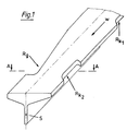
- An asymmetrical T-profile (FIG. 1) has two elongated small recesses Rk1, Rk2 in the rolling direction W on the left flange. Opposite of Rk2 there is a large recess in the right flange, which becomes deeper as the length of the roll increases and which extends into the vicinity of the web S.
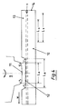
- FIG. 2 represents a section along line A-A through the T profile according to FIG. 1.
- the table shows the absolute values of the profile dimension according to FIG. 2 for a finished rolled asymmetrical profile with differently sized recesses on both flanges.
- the radius ri of the incircle between the ridges rs and the flange outer surface Fa is dimensioned such that the incircle surface Fi is greater than the sum of the cross-sectional areas FRk2 and FRg of the rolled-in recesses Rk2 and Rg.
- the cross-sectional area of the profile according to FIG. 2 within the outer contour - i.e. taking into account the cross-sectional areas of the recesses - was reduced by at least 10%, which, however, had only an insignificant influence on the depth and shape of the recesses previously formed.
- FIG. 3 shows a top view of a component composed of the T-profiles 1, 2, 3 and welded to the flanges 7.
- the profiles 1, 2, 3 have small recesses 4 and large recesses 5, which were rolled into the profile flanges 7 at periodic intervals, the divisions Tk and Tg. After dividing the endless rolled sections into sections 1, 2, 3, these were joined together in such a way that an opening 8 was formed from two recesses 4 or an opening 6 from recesses 5.
- openings 6, 8 are used for the positive fastening of other components, not shown, for example for concrete slab formwork.
- Fig. 4 shows schematically the relationships between finished profile 14 with asymmetrical flanges 10, 13 and web S with recess 12 and the caliber roller 9 with the recess 12 producing the recess contour 11.
- the caliber contour 11 is next to one for better clarity shown by them generated return 12 and not in direct engagement with the profile to generate this return.
- the caliber roll 9 rotates in the rolling direction W.
- This shortening of the caliber contour 11 must therefore take into account both the final insertion and the additional extension in the area of the recess.
- This finding according to the invention can be applied to all elongated recess forms of profiles. It must also be taken into account when dividing between periodically successive recesses on one or more flange ends. With regard to the division, it should also be noted that even when deep, long recesses are rolled in, a certain extension can occur in the flange nodes.
- the steel profiles produced by the process according to the invention have a substantially constant cross section which can only be changed by the recesses provided, the incircle of the flange knot also being at least as large as the sum in the finished profile the recessed cross sections formed on a cross section.
- a sufficient incircle can be achieved by means of a suitable web thickness and / or a suitable radius between the web and flange, the web thickness and radius preferably being greater than 5% of the height of the profile.
- the hot-rolled steel profile according to the invention with recesses which are rolled in periodically at the flange ends and which are rolled at least partially up to the vicinity of the flange node, is used, as can be seen from FIG. 3, as a partial profile for a welded larger profile with openings.
- the partial profiles each have recesses in mirror image, so that a pair of recesses forms a breakthrough through a common surface after the partial profiles have been joined together.
Landscapes
- Engineering & Computer Science (AREA)
- Mining & Mineral Resources (AREA)
- Mechanical Engineering (AREA)
- Life Sciences & Earth Sciences (AREA)
- General Life Sciences & Earth Sciences (AREA)
- Geochemistry & Mineralogy (AREA)
- Geology (AREA)
- Metal Rolling (AREA)
- Reduction Rolling/Reduction Stand/Operation Of Reduction Machine (AREA)
- Heat Treatment Of Steel (AREA)
- Coating With Molten Metal (AREA)
- Preliminary Treatment Of Fibers (AREA)
Priority Applications (1)
| Application Number | Priority Date | Filing Date | Title |
|---|---|---|---|
| AT89730048T ATE79572T1 (de) | 1988-03-02 | 1989-02-28 | Verfahren zum herstellen eines stahlprofiles, dessen anwendung und profil. |
Applications Claiming Priority (2)
| Application Number | Priority Date | Filing Date | Title |
|---|---|---|---|
| DE3807211 | 1988-03-02 | ||
| DE3807211A DE3807211A1 (de) | 1988-03-02 | 1988-03-02 | Stahlprofil und verfahren zum herstellen eines stahlprofiles |
Publications (3)
| Publication Number | Publication Date |
|---|---|
| EP0331618A2 true EP0331618A2 (fr) | 1989-09-06 |
| EP0331618A3 EP0331618A3 (fr) | 1991-01-02 |
| EP0331618B1 EP0331618B1 (fr) | 1992-08-19 |
Family
ID=6348924
Family Applications (1)
| Application Number | Title | Priority Date | Filing Date |
|---|---|---|---|
| EP89730048A Expired - Lifetime EP0331618B1 (fr) | 1988-03-02 | 1989-02-28 | Procédé pour la fabrication d'un profilé en acier, son application et profilé |
Country Status (4)
| Country | Link |
|---|---|
| EP (1) | EP0331618B1 (fr) |
| AT (1) | ATE79572T1 (fr) |
| DE (2) | DE3807211A1 (fr) |
| ES (1) | ES2034742T3 (fr) |
Family Cites Families (6)
| Publication number | Priority date | Publication date | Assignee | Title |
|---|---|---|---|---|
| GB704338A (en) * | 1949-10-24 | 1954-02-17 | Groetschel Karl Maria | Improvements in lagging members for mines |
| DE976549C (de) * | 1949-10-25 | 1963-11-07 | Karl M Dipl Berging Groetschel | Ausbautraeger, insbesondere fuer den Strebausbau |
| GB786538A (en) * | 1954-09-14 | 1957-11-20 | Gutehoffnungshuette Sterkrade | Improvements in and relating to caps for supporting mine roofs |
| DE1602021A1 (de) * | 1967-10-26 | 1970-05-06 | Arbed Vereinigte Huettenwerke | Verfahren zur Herstellung von auf der Schmalseite profilierten Baendern |
| DE3307230A1 (de) * | 1982-03-09 | 1983-10-20 | Stahlwerke Peine-Salzgitter Ag, 3150 Peine | Grubenausbauprofil fuer formschluessigen anschluss |
| DE3629214A1 (de) * | 1986-08-28 | 1988-03-10 | Armo Bauelemente | Ausbauprofil fuer den gruben- und tunnelausbau |
-
1988
- 1988-03-02 DE DE3807211A patent/DE3807211A1/de not_active Ceased
-
1989
- 1989-02-28 EP EP89730048A patent/EP0331618B1/fr not_active Expired - Lifetime
- 1989-02-28 DE DE8989730048T patent/DE58902061D1/de not_active Expired - Lifetime
- 1989-02-28 ES ES198989730048T patent/ES2034742T3/es not_active Expired - Lifetime
- 1989-02-28 AT AT89730048T patent/ATE79572T1/de not_active IP Right Cessation
Also Published As
| Publication number | Publication date |
|---|---|
| ATE79572T1 (de) | 1992-09-15 |
| ES2034742T3 (es) | 1993-04-01 |
| DE3807211A1 (de) | 1989-09-14 |
| EP0331618A3 (fr) | 1991-01-02 |
| EP0331618B1 (fr) | 1992-08-19 |
| DE58902061D1 (de) | 1992-09-24 |
Similar Documents
| Publication | Publication Date | Title |
|---|---|---|
| DE69227260T2 (de) | Flachgewalztes metallprofil mit versteifungseinprägungen | |
| DE3124566C2 (fr) | ||
| DE3220029C2 (fr) | ||
| DE1452122B1 (de) | Verfahren zum Herstellen beispielsweise U-,Winkel-,Rinnen-,Rohr- oder ähnliche Formen aufweisender,hochfester,dehnungsarmer Blechprofile und Einrichtung zur Durchführung des Verfahrens | |
| EP2313216B1 (fr) | Procédé de fabrication d'un profilé laminé à froid présentant au moins un bord profilé épaissi | |
| DE10041280C2 (de) | Verfahren und Vorrichtung zum flexiblen Walzen eines Metallbandes | |
| DE19543414B4 (de) | Verfahren zum Warmwalzen von Spundwandbohlen mit Z-förmigem Querschnitt | |
| DE10113610A1 (de) | Verfahren zur Ausbildung dickenprofilierter einstückiger Blechteile | |
| DE4231213C2 (de) | Verfahren zum Herstellen eines trägerartigen Formkörpers | |
| DE60023820T2 (de) | Verfahren zur Herstellung von gebogenen und deformierten metallischen Teilen | |
| DE3636478A1 (de) | Verfahren und anordnung zum walzen von stranggegossenen profilen | |
| DE1452020A1 (de) | Verfahren zum Walzen von Schienenprofilen | |
| DE3223346A1 (de) | Verfahren zum richten von eisenbahnschienen und durch das verfahren hergestellte eisenbahnschienen | |
| DE3222930C2 (fr) | ||
| DE69120895T2 (de) | Verfahren zum Walzen von Doppel-T-Trägern | |
| DE2912504A1 (de) | Verfahren zum walzen von stahlprofilen mit abgewinkelten oder gestauchten raendern | |
| DE3410160A1 (de) | Verfahren zum integralen universalwalzen metallischer walzprofile des h- oder i-traegertyps | |
| DE538635C (de) | Verfahren zur Herstellung durchbrochener Metallgegenstaende | |
| EP0331618B1 (fr) | Procédé pour la fabrication d'un profilé en acier, son application et profilé | |
| EP3085471A1 (fr) | Procede de fabrication d'un composant structural et dispositif de laminage correspondant | |
| DE2634576A1 (de) | Kaltgewalzter doppel-t-traeger | |
| DE430879C (de) | Verfahren zum Walzen hoher Traeger mit duennem Steg | |
| DE3302333C2 (fr) | ||
| DE2359308A1 (de) | Verfahren zum herstellen eines metallstreifens mit einem laengskanal | |
| DE3341957A1 (de) | Gerippter betonbewehrungsstahl sowie verfahren zu seiner herstellung |
Legal Events
| Date | Code | Title | Description |
|---|---|---|---|
| PUAI | Public reference made under article 153(3) epc to a published international application that has entered the european phase |
Free format text: ORIGINAL CODE: 0009012 |
|
| AK | Designated contracting states |
Kind code of ref document: A2 Designated state(s): AT BE CH DE ES FR GB GR IT LI LU NL SE |
|
| PUAL | Search report despatched |
Free format text: ORIGINAL CODE: 0009013 |
|
| AK | Designated contracting states |
Kind code of ref document: A3 Designated state(s): AT BE CH DE ES FR GB GR IT LI LU NL SE |
|
| 17P | Request for examination filed |
Effective date: 19901221 |
|
| 17Q | First examination report despatched |
Effective date: 19911018 |
|
| RTI1 | Title (correction) | ||
| GRAA | (expected) grant |
Free format text: ORIGINAL CODE: 0009210 |
|
| RAP3 | Party data changed (applicant data changed or rights of an application transferred) |
Owner name: PREUSSAG STAHL AKTIENGESELLSCHAFT |
|
| AK | Designated contracting states |
Kind code of ref document: B1 Designated state(s): AT BE CH DE ES FR GB GR IT LI LU NL SE |
|
| PG25 | Lapsed in a contracting state [announced via postgrant information from national office to epo] |
Ref country code: SE Free format text: THE PATENT HAS BEEN ANNULLED BY A DECISION OF A NATIONAL AUTHORITY Effective date: 19920819 Ref country code: NL Effective date: 19920819 Ref country code: GR Free format text: LAPSE BECAUSE OF FAILURE TO SUBMIT A TRANSLATION OF THE DESCRIPTION OR TO PAY THE FEE WITHIN THE PRESCRIBED TIME-LIMIT Effective date: 19920819 |
|
| REF | Corresponds to: |
Ref document number: 79572 Country of ref document: AT Date of ref document: 19920915 Kind code of ref document: T |
|
| REF | Corresponds to: |
Ref document number: 58902061 Country of ref document: DE Date of ref document: 19920924 |
|
| ITF | It: translation for a ep patent filed | ||
| ET | Fr: translation filed | ||
| GBT | Gb: translation of ep patent filed (gb section 77(6)(a)/1977) |
Effective date: 19921130 |
|
| NLV1 | Nl: lapsed or annulled due to failure to fulfill the requirements of art. 29p and 29m of the patents act | ||
| PG25 | Lapsed in a contracting state [announced via postgrant information from national office to epo] |
Ref country code: LI Effective date: 19930228 Ref country code: CH Effective date: 19930228 Ref country code: AT Effective date: 19930228 |
|
| REG | Reference to a national code |
Ref country code: ES Ref legal event code: FG2A Ref document number: 2034742 Country of ref document: ES Kind code of ref document: T3 |
|
| PLBE | No opposition filed within time limit |
Free format text: ORIGINAL CODE: 0009261 |
|
| STAA | Information on the status of an ep patent application or granted ep patent |
Free format text: STATUS: NO OPPOSITION FILED WITHIN TIME LIMIT |
|
| 26N | No opposition filed | ||
| REG | Reference to a national code |
Ref country code: CH Ref legal event code: PL |
|
| EPTA | Lu: last paid annual fee | ||
| PGFP | Annual fee paid to national office [announced via postgrant information from national office to epo] |
Ref country code: FR Payment date: 19950113 Year of fee payment: 7 |
|
| PGFP | Annual fee paid to national office [announced via postgrant information from national office to epo] |
Ref country code: GB Payment date: 19950119 Year of fee payment: 7 |
|
| PGFP | Annual fee paid to national office [announced via postgrant information from national office to epo] |
Ref country code: BE Payment date: 19950126 Year of fee payment: 7 |
|
| PGFP | Annual fee paid to national office [announced via postgrant information from national office to epo] |
Ref country code: LU Payment date: 19950201 Year of fee payment: 7 |
|
| PGFP | Annual fee paid to national office [announced via postgrant information from national office to epo] |
Ref country code: ES Payment date: 19950208 Year of fee payment: 7 |
|
| PG25 | Lapsed in a contracting state [announced via postgrant information from national office to epo] |
Ref country code: LU Free format text: LAPSE BECAUSE OF NON-PAYMENT OF DUE FEES Effective date: 19960228 Ref country code: GB Effective date: 19960228 Ref country code: BE Effective date: 19960228 |
|
| PG25 | Lapsed in a contracting state [announced via postgrant information from national office to epo] |
Ref country code: ES Free format text: LAPSE BECAUSE OF THE APPLICANT RENOUNCES Effective date: 19960301 |
|
| BERE | Be: lapsed |
Owner name: PREUSSAG STAHL A.G. Effective date: 19960228 |
|
| GBPC | Gb: european patent ceased through non-payment of renewal fee |
Effective date: 19960228 |
|
| PG25 | Lapsed in a contracting state [announced via postgrant information from national office to epo] |
Ref country code: FR Effective date: 19961031 |
|
| REG | Reference to a national code |
Ref country code: FR Ref legal event code: ST |
|
| PGFP | Annual fee paid to national office [announced via postgrant information from national office to epo] |
Ref country code: DE Payment date: 19980217 Year of fee payment: 10 |
|
| PG25 | Lapsed in a contracting state [announced via postgrant information from national office to epo] |
Ref country code: DE Free format text: LAPSE BECAUSE OF NON-PAYMENT OF DUE FEES Effective date: 19991201 |
|
| REG | Reference to a national code |
Ref country code: ES Ref legal event code: FD2A Effective date: 19991007 |
|
| PG25 | Lapsed in a contracting state [announced via postgrant information from national office to epo] |
Ref country code: IT Free format text: LAPSE BECAUSE OF NON-PAYMENT OF DUE FEES;WARNING: LAPSES OF ITALIAN PATENTS WITH EFFECTIVE DATE BEFORE 2007 MAY HAVE OCCURRED AT ANY TIME BEFORE 2007. THE CORRECT EFFECTIVE DATE MAY BE DIFFERENT FROM THE ONE RECORDED. Effective date: 20050228 |