EP0331484A2 - Coffrage avec mécanisme de décoffrage manuel - Google Patents
Coffrage avec mécanisme de décoffrage manuel Download PDFInfo
- Publication number
- EP0331484A2 EP0331484A2 EP89302076A EP89302076A EP0331484A2 EP 0331484 A2 EP0331484 A2 EP 0331484A2 EP 89302076 A EP89302076 A EP 89302076A EP 89302076 A EP89302076 A EP 89302076A EP 0331484 A2 EP0331484 A2 EP 0331484A2
- Authority
- EP
- European Patent Office
- Prior art keywords
- boards
- shaft
- support
- faces
- face
- Prior art date
- Legal status (The legal status is an assumption and is not a legal conclusion. Google has not performed a legal analysis and makes no representation as to the accuracy of the status listed.)
- Granted
Links
- 238000000465 moulding Methods 0.000 title claims abstract description 24
- 230000007246 mechanism Effects 0.000 title claims description 15
- 125000006850 spacer group Chemical group 0.000 claims abstract description 34
- 230000001154 acute effect Effects 0.000 claims description 4
- 230000000295 complement effect Effects 0.000 claims 1
- 238000009415 formwork Methods 0.000 description 3
- 238000010276 construction Methods 0.000 description 2
- 230000000712 assembly Effects 0.000 description 1
- 238000000429 assembly Methods 0.000 description 1
Images

Classifications
-
- B—PERFORMING OPERATIONS; TRANSPORTING
- B28—WORKING CEMENT, CLAY, OR STONE
- B28B—SHAPING CLAY OR OTHER CERAMIC COMPOSITIONS; SHAPING SLAG; SHAPING MIXTURES CONTAINING CEMENTITIOUS MATERIAL, e.g. PLASTER
- B28B7/00—Moulds; Cores; Mandrels
- B28B7/22—Moulds for making units for prefabricated buildings, i.e. units each comprising an important section of at least two limiting planes of a room or space, e.g. cells; Moulds for making prefabricated stair units
-
- E—FIXED CONSTRUCTIONS
- E04—BUILDING
- E04G—SCAFFOLDING; FORMS; SHUTTERING; BUILDING IMPLEMENTS OR AIDS, OR THEIR USE; HANDLING BUILDING MATERIALS ON THE SITE; REPAIRING, BREAKING-UP OR OTHER WORK ON EXISTING BUILDINGS
- E04G11/00—Forms, shutterings, or falsework for making walls, floors, ceilings, or roofs
- E04G11/06—Forms, shutterings, or falsework for making walls, floors, ceilings, or roofs for walls, e.g. curved end panels for wall shutterings; filler elements for wall shutterings; shutterings for vertical ducts
- E04G11/08—Forms, which are completely dismantled after setting of the concrete and re-built for next pouring
- E04G11/082—Retractable forms for the inside face of at least three walls
Definitions
- This invention relates to a molding device for concrete construction which can be released easily from a formed concrete structure and easily reset at another location for next molding.
- 4,679,762 of the inventor of this application discloses a form assembly which is used to form an enclosed multi-sided wall as shown in Figure 1 and includes component boards and wedge-shaped spacer boards which are operated by a rack-and-gear mechanism including a plurality of worm wheels mounted on vertical shafts and horizontal shafts to drive rack members.
- a rack-and-gear mechanism including a plurality of worm wheels mounted on vertical shafts and horizontal shafts to drive rack members.
- the spacer boards must be moved inward simultaneously.
- the form boards on two sides of the spacer boards also move simultaneously so that a great deal of force is needed to simultaneously release the entire form assembly. Accordingly, a powerful hydraulic device is necessary for operation.
- this form assembly is suitable only for forming enclosed multi-sided walls.
- An object of the invention is to provide a molding device which has a simple construction and which can be operated easily and with less power than that required by the prior form assemblies.
- Another object of the invention is to provide a molding device for forming an enclosed multi-sided wall which can be released in part from the formed wall.
- Still another object of the invention is to provide a molding device which can easily be removed manually from the formed structure.
- a molding device comprises: a first component form board having a first forming face and a first end face connected to the forming face and forming an acute angle with a line normal to the first forming face; a second component form board having a second forming face and a second end face connected to the second forming face and forming an acute angle with a line normal to the second forming face, the second end face being abutted with and releasably connected to the first end face; means for releaseably connecting the first and second component form boards; and an operating unit associated with the first and second form boards and being operable to move said first and second form boards relative to one another, the unit including a rack member mounted on the first form board, a lever mounted on the second form board for turning about a horizontal axis adjacent to the rack member, a pawl member connected with the lever to swing about a horizontal axis which is eccentric with respect to the axis of the lever, the pawl member engaging with the rack member and displacing the rack member when
- the molding device includes a wedge-shaped spacer board placed between the two form boards, and the operating means moves the spacer board relative to each of the form boards.
- the operating unit further includes a mounting seat mounted on each component board, and having at least one mounting hole, the lever having a shaft removably inserted in the mounting hole and an elongated handle connected to the shaft for turning the shaft, the operating unit further having an eccentric member fixed to the shaft, the pawl member having one end rotatably sleeved around the eccentric member.
- the rack member includes a thick plate member having a top surface with rack teeth formed thereon and an upward edge flange thereon, the spacer board having an accommodating recess for removably receiving the rack member so as to change the position of the rack member as desired.
- the pawl member has a free end which has two opposite edge teeth either of which can engage with the rack teeth.
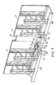
- a molding device 11 for molding an inner side of a four-sided wall including two angled component form boards 12, two angled component form boards 13 and four spacer boards 14 which are interconnected to establish a four-sided forming face for a four wall room.
- Each spacer board 14 has a wedge-shaped cross-section and two diverging end faces 14a extending from a forming face 14b of the spacer board 14.
- Each form board 12 has two inclined end faces 12a abutting with and connected releaseably to adjacent end faces 14a of the spacer board 14.
- each form board 13 has two inclined end faces 13a abutting with and connected releaseably to adjacent end faces 14a of the spacer board 14.
- Support bases 12c, 13c and 14c are disposed respectively at the bottom sides of the form boards 12 and 13 and the spacer boards 14.
- each slanted side of the base 12c or 13c is provided with an elongated groove 21 which has a restricted elongated opening 21a and receives an elongated bar 22 in a slideable position.
- Each bar 22 is connected through screws 23 to one side of the base 14c of each spacer board 14. The bar 22 can be prevented from moving in the groove 21 by tightening the screws 23, thereby securing together the spacer board 14 and the adjacent form board 12 and 13.
- each spacer board 14 On the base 14c of each spacer board 14 are mounted two rack members 18 near the end faces of the spacer board 14.
- Each rack member 18 is a thick plate which is provided with teeth 19 at the top surface thereof and an upward stop edge flange 20.
- the rack member 18 is attached removably to the base 14c. The removable attachment may be accomplished by placing the rack member in a recess 181 of the base 14c.
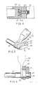
- an operating means 25 is mounted through a mounting seat 15 on one side of each base 12c or 13c adjacent to each rack member 18.
- the mounting seat 15 includes two raised parts provided respectively with outer and inner journal holes 16 and 17 and a stop projection 15a.
- the stop projection 15a is used to engage with the stop flange 20 of the rack member so as to stop the movement of the rack member.
- an operating means 25, to operably associate with the rack member includes a lever 26 connected to an operating shaft 27 which can be inserted changeably in two mounting holes 16 and 17.
- An eccentric member 34 is mounted on the shaft 27 adjacent to the lever 26.
- a pawl member 28 is sleeved with one end thereof rotatably around the eccentric member 34.
- the free end of the pawl member 28 has two opposed edge teeth 29 and 30.
- Adjacent to the eccentric member 34 is another pawl member 31 which is mounted on an end portion of the shaft 27 to swing thereabout and which is prevented from escaping by means of a locking screw 36.
- the pawl also has two opposed edge teeth 32 and 33.
- FIG. 10 The operation of releasing the form of the invention is illustrated in Figure 10. Firstly, the two form boards 13 are moved inward by operating the levers 26 so as to move the spacer boards 14 in the directions shown by arrow A relative to the form boards 12. Then, the form boards 12 are moved in the directions shown by arrow B by moving inward the spacer boards 14 relative to the form boards 13. The movement of the two form boards 12 or 13 can be effected either simultaneously or successively.
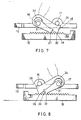
- the eccentric member 34 will cause the pawl member 28 to move slightly forward, thereby moving forward the rack member.
- the pawl member 28 moves rearward and engages with a next tooth of the rack member.
- the rack member 18 can be moved in a direction shown by arrow 50 to cause the spacer board 14 and the form board 13 to move to their molding positions.
- the movement of the rack member 18 stops when the flange 20 of the rack 18 contacts the projection 15a of the mounting seat 15.
- the tooth 32 of the pawl 31 prevents the backward movement of the rack member when the lever is operated.
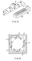
- FIG 9 shows an alternative mounting seat 80 and an alternative rack member 82 which can be used in the present invention.
- the mounting seat 80 includes a single mounting hole 81 into which the shaft 27 can be inserted for moving the rack member in two directions.
- the rack member 82 is received removably in the recess 181 of the base member 14c so that the rack member 82 can be detached from the base member 14c to change its position. Since a single hole is provided on the mounting seat 80, the length of the rack member 82 must be greater than that of the rack member 18.
- the teeth of the rack members 18 and 82 are arranged such that their positions must be changed to be able to engage with the teeth 29 and 30 of the pawl arm 28 so as to move the rack members 18 and 82 in two directions, i.e. to a molding position and to a released position
- the teeth of the rack member or the pawl used in the present invention may be arranged such that they are operative without changing the position of the rack member.
- the form assembly according to the invention can be operated manually to move to a molding position or a position released from the molded concrete structure, and that the simultaneous operations of the two operating means of each form board 12 or 13 can move the form board 12 or 13 relative to the adjacent spacer boards 14.
Landscapes
- Engineering & Computer Science (AREA)
- Architecture (AREA)
- Mechanical Engineering (AREA)
- Civil Engineering (AREA)
- Structural Engineering (AREA)
- Manufacturing & Machinery (AREA)
- Chemical & Material Sciences (AREA)
- Ceramic Engineering (AREA)
- Moulds, Cores, Or Mandrels (AREA)
- Forms Removed On Construction Sites Or Auxiliary Members Thereof (AREA)
- Moulds For Moulding Plastics Or The Like (AREA)
Priority Applications (1)
| Application Number | Priority Date | Filing Date | Title |
|---|---|---|---|
| AT89302076T ATE85386T1 (de) | 1988-03-02 | 1989-03-02 | Schalung mit handbedientem entschalungsmechanism. |
Applications Claiming Priority (2)
| Application Number | Priority Date | Filing Date | Title |
|---|---|---|---|
| JP28582/88 | 1988-03-02 | ||
| JP1988028582U JPH071435Y2 (ja) | 1988-03-02 | 1988-03-02 | 型わくの力伝達機構 |
Publications (3)
| Publication Number | Publication Date |
|---|---|
| EP0331484A2 true EP0331484A2 (fr) | 1989-09-06 |
| EP0331484A3 EP0331484A3 (en) | 1990-05-30 |
| EP0331484B1 EP0331484B1 (fr) | 1993-02-03 |
Family
ID=12252595
Family Applications (1)
| Application Number | Title | Priority Date | Filing Date |
|---|---|---|---|
| EP89302076A Expired - Lifetime EP0331484B1 (fr) | 1988-03-02 | 1989-03-02 | Coffrage avec mécanisme de décoffrage manuel |
Country Status (5)
| Country | Link |
|---|---|
| EP (1) | EP0331484B1 (fr) |
| JP (1) | JPH071435Y2 (fr) |
| CN (1) | CN1015564B (fr) |
| AT (1) | ATE85386T1 (fr) |
| DE (1) | DE68904661T2 (fr) |
Cited By (1)
| Publication number | Priority date | Publication date | Assignee | Title |
|---|---|---|---|---|
| CN112538963A (zh) * | 2020-12-08 | 2021-03-23 | 姜大山 | 一种用于建筑工程施工可拆卸、易清理的建筑模板 |
Families Citing this family (4)
| Publication number | Priority date | Publication date | Assignee | Title |
|---|---|---|---|---|
| CN103434017B (zh) * | 2013-08-05 | 2015-09-16 | 兖州嘉禾建筑设备有限公司 | 柔性状态下的四轴联动脱模装置 |
| CN105239772B (zh) * | 2015-09-01 | 2017-09-22 | 中民筑友有限公司 | 调节机构、内筒模以及电梯井模板装置 |
| CN107813409B (zh) * | 2017-10-27 | 2021-01-29 | 李宜君 | 一种建筑墙体成型模具的内模及其缩模方法 |
| CN117145195A (zh) * | 2023-07-29 | 2023-12-01 | 陕西玉蜂工程机械有限公司 | 一种楔式联动变形模板的制作方法 |
Family Cites Families (7)
| Publication number | Priority date | Publication date | Assignee | Title |
|---|---|---|---|---|
| US2031815A (en) * | 1935-09-05 | 1936-02-25 | Duplex Tool Co | Lifting jack |
| US3481581A (en) * | 1967-08-24 | 1969-12-02 | Joe N Sunseri | Lifting jack |
| FR2410110A1 (fr) * | 1977-11-29 | 1979-06-22 | Equip Modernes Indls | Procede et materiel de realisation du mur perimetrique d'une enceinte en beton |
| US4570896A (en) * | 1984-02-06 | 1986-02-18 | Strickland Systems, Inc. | Slide action inside corner form |
| JPS61237762A (ja) * | 1984-12-13 | 1986-10-23 | 李 淵河 | 型わくの組立、解体装置 |
| US4614326A (en) * | 1985-01-09 | 1986-09-30 | Strickland Systems, Inc. | Concrete mold core assembly |
| IN166742B (fr) * | 1985-11-26 | 1990-07-14 | Yuan Ho Lee |
-
1988
- 1988-03-02 JP JP1988028582U patent/JPH071435Y2/ja not_active Expired - Lifetime
-
1989
- 1989-02-28 CN CN89101038.6A patent/CN1015564B/zh not_active Expired
- 1989-03-02 DE DE8989302076T patent/DE68904661T2/de not_active Expired - Fee Related
- 1989-03-02 AT AT89302076T patent/ATE85386T1/de not_active IP Right Cessation
- 1989-03-02 EP EP89302076A patent/EP0331484B1/fr not_active Expired - Lifetime
Cited By (1)
| Publication number | Priority date | Publication date | Assignee | Title |
|---|---|---|---|---|
| CN112538963A (zh) * | 2020-12-08 | 2021-03-23 | 姜大山 | 一种用于建筑工程施工可拆卸、易清理的建筑模板 |
Also Published As
| Publication number | Publication date |
|---|---|
| ATE85386T1 (de) | 1993-02-15 |
| EP0331484B1 (fr) | 1993-02-03 |
| DE68904661D1 (de) | 1993-03-18 |
| CN1015564B (zh) | 1992-02-19 |
| EP0331484A3 (en) | 1990-05-30 |
| JPH01130448U (fr) | 1989-09-05 |
| JPH071435Y2 (ja) | 1995-01-18 |
| DE68904661T2 (de) | 1993-08-12 |
| CN1036243A (zh) | 1989-10-11 |
Similar Documents
| Publication | Publication Date | Title |
|---|---|---|
| JPH0711921Y2 (ja) | 作業台の刃物位置設定装置 | |
| US5071384A (en) | Steering mechanism | |
| US7299720B1 (en) | Reversible ratchet wrench | |
| US4846438A (en) | Molding device with hand operable mold | |
| EP0331484B1 (fr) | Coffrage avec mécanisme de décoffrage manuel | |
| JPH11198730A (ja) | 車両用物品キャリヤ | |
| US4502393A (en) | Worktable, particularly an office desk | |
| KR100790963B1 (ko) | 내부 벽을 위한 거푸집틀 구성 방법 | |
| US5983762A (en) | Punch catch device | |
| US3844526A (en) | Vertical shaft form with cammed stripping units | |
| JPH026651B2 (fr) | ||
| US20020074060A1 (en) | Wood planing machine with a tightening unit | |
| EP0225093A1 (fr) | Coffrage pour cellules-éléments | |
| CN218061416U (zh) | 组合楼板施工悬挑部模板支撑工具 | |
| DE3821206A1 (de) | Video-projektionseinrichtung mit schwenk-hub-anlage | |
| CN220922189U (zh) | 一种旋转装配装置 | |
| KR102811150B1 (ko) | 건축물용 비계 지지장치 | |
| JP3743784B2 (ja) | 二重床用床パネルの支持装置 | |
| EP0374109B1 (fr) | Support mobile et démontable pour échafaudages | |
| KR800000393B1 (ko) | 창틀이 부착된 콘크리트 판넬의 성형장치 | |
| JPS6313701Y2 (fr) | ||
| US5799447A (en) | Apparatus for moving a wall form assembly | |
| JPH0316497Y2 (fr) | ||
| JPH0529445U (ja) | 椅子における操作部材取付構造 | |
| JPH04126815U (ja) | 擁壁のコーナブロツク成形用型枠 |
Legal Events
| Date | Code | Title | Description |
|---|---|---|---|
| PUAI | Public reference made under article 153(3) epc to a published international application that has entered the european phase |
Free format text: ORIGINAL CODE: 0009012 |
|
| AK | Designated contracting states |
Kind code of ref document: A2 Designated state(s): AT BE CH DE ES FR GR IT LI LU NL SE |
|
| PUAL | Search report despatched |
Free format text: ORIGINAL CODE: 0009013 |
|
| AK | Designated contracting states |
Kind code of ref document: A3 Designated state(s): AT BE CH DE ES FR GR IT LI LU NL SE |
|
| 17P | Request for examination filed |
Effective date: 19900921 |
|
| 17Q | First examination report despatched |
Effective date: 19910605 |
|
| GRAA | (expected) grant |
Free format text: ORIGINAL CODE: 0009210 |
|
| AK | Designated contracting states |
Kind code of ref document: B1 Designated state(s): AT BE CH DE ES FR GR IT LI LU NL SE |
|
| PG25 | Lapsed in a contracting state [announced via postgrant information from national office to epo] |
Ref country code: SE Effective date: 19930203 Ref country code: LI Effective date: 19930203 Ref country code: GR Free format text: LAPSE BECAUSE OF FAILURE TO SUBMIT A TRANSLATION OF THE DESCRIPTION OR TO PAY THE FEE WITHIN THE PRESCRIBED TIME-LIMIT Effective date: 19930203 Ref country code: ES Free format text: THE PATENT HAS BEEN ANNULLED BY A DECISION OF A NATIONAL AUTHORITY Effective date: 19930203 Ref country code: CH Effective date: 19930203 Ref country code: BE Effective date: 19930203 Ref country code: AT Effective date: 19930203 |
|
| REF | Corresponds to: |
Ref document number: 85386 Country of ref document: AT Date of ref document: 19930215 Kind code of ref document: T |
|
| REF | Corresponds to: |
Ref document number: 68904661 Country of ref document: DE Date of ref document: 19930318 |
|
| PG25 | Lapsed in a contracting state [announced via postgrant information from national office to epo] |
Ref country code: LU Free format text: LAPSE BECAUSE OF NON-PAYMENT OF DUE FEES Effective date: 19930331 |
|
| ITF | It: translation for a ep patent filed | ||
| REG | Reference to a national code |
Ref country code: CH Ref legal event code: PL |
|
| ET | Fr: translation filed | ||
| PLBE | No opposition filed within time limit |
Free format text: ORIGINAL CODE: 0009261 |
|
| STAA | Information on the status of an ep patent application or granted ep patent |
Free format text: STATUS: NO OPPOSITION FILED WITHIN TIME LIMIT |
|
| 26N | No opposition filed | ||
| PGFP | Annual fee paid to national office [announced via postgrant information from national office to epo] |
Ref country code: DE Payment date: 19970307 Year of fee payment: 9 |
|
| PGFP | Annual fee paid to national office [announced via postgrant information from national office to epo] |
Ref country code: FR Payment date: 19970313 Year of fee payment: 9 |
|
| PGFP | Annual fee paid to national office [announced via postgrant information from national office to epo] |
Ref country code: NL Payment date: 19970327 Year of fee payment: 9 |
|
| PG25 | Lapsed in a contracting state [announced via postgrant information from national office to epo] |
Ref country code: FR Free format text: THE PATENT HAS BEEN ANNULLED BY A DECISION OF A NATIONAL AUTHORITY Effective date: 19980331 |
|
| PG25 | Lapsed in a contracting state [announced via postgrant information from national office to epo] |
Ref country code: NL Free format text: LAPSE BECAUSE OF NON-PAYMENT OF DUE FEES Effective date: 19981001 |
|
| NLV4 | Nl: lapsed or anulled due to non-payment of the annual fee |
Effective date: 19981001 |
|
| PG25 | Lapsed in a contracting state [announced via postgrant information from national office to epo] |
Ref country code: DE Free format text: LAPSE BECAUSE OF NON-PAYMENT OF DUE FEES Effective date: 19981201 |
|
| REG | Reference to a national code |
Ref country code: FR Ref legal event code: ST |
|
| PG25 | Lapsed in a contracting state [announced via postgrant information from national office to epo] |
Ref country code: IT Free format text: LAPSE BECAUSE OF NON-PAYMENT OF DUE FEES Effective date: 20050302 |