EP0331445A2 - Verfahren und Vorrichtung für ein digitales sonisches Messsystem für Spulen - Google Patents
Verfahren und Vorrichtung für ein digitales sonisches Messsystem für Spulen Download PDFInfo
- Publication number
- EP0331445A2 EP0331445A2 EP89302001A EP89302001A EP0331445A2 EP 0331445 A2 EP0331445 A2 EP 0331445A2 EP 89302001 A EP89302001 A EP 89302001A EP 89302001 A EP89302001 A EP 89302001A EP 0331445 A2 EP0331445 A2 EP 0331445A2
- Authority
- EP
- European Patent Office
- Prior art keywords
- microphones
- banks
- measured
- sounds
- recited
- Prior art date
- Legal status (The legal status is an assumption and is not a legal conclusion. Google has not performed a legal analysis and makes no representation as to the accuracy of the status listed.)
- Ceased
Links
Images


Classifications
-
- G—PHYSICS
- G01—MEASURING; TESTING
- G01R—MEASURING ELECTRIC VARIABLES; MEASURING MAGNETIC VARIABLES
- G01R27/00—Arrangements for measuring resistance, reactance, impedance, or electric characteristics derived therefrom
- G01R27/02—Measuring real or complex resistance, reactance, impedance, or other two-pole characteristics derived therefrom, e.g. time constant
- G01R27/26—Measuring inductance or capacitance; Measuring quality factor, e.g. by using the resonance method; Measuring loss factor; Measuring dielectric constants ; Measuring impedance or related variables
-
- G—PHYSICS
- G01—MEASURING; TESTING
- G01B—MEASURING LENGTH, THICKNESS OR SIMILAR LINEAR DIMENSIONS; MEASURING ANGLES; MEASURING AREAS; MEASURING IRREGULARITIES OF SURFACES OR CONTOURS
- G01B17/00—Measuring arrangements characterised by the use of infrasonic, sonic or ultrasonic vibrations
Definitions
- the present invention is related to three-dimensional measurement of an object with varying dimensions in all three directions and, more particularly, to a system for measuring stator half coils and full coils.
- stator coils formed by two "half coils". Each half coil may be as long as 11 m (36 ft.) in a large generator.
- the stator half coils typically have a rectangular cross-section and are formed of stacks of thin metal strips covered with insulation surrounded by tape spirally wound on the coil.
- the central section of a stator half coil comprises the majority of its length and is straight.
- the end sections of a stator half coil form a complex curve, part of which is shaped like an involute on the inside of a cone.
- An example of the end section 10 of a conventional stator half coil 11 is illustrated in Fig. 1.
- the stator coil has a rectangular cross-section and the complex curvature of the stator coil end 10 can be seen in the perspective view of Fig. 1.
- stator half coils It is important to manufacture stator half coils so that their actual or measured shape matches the designed shape within relatively close tolerances.
- the ends 14 of the straight section 16 should align within 0.04 cm (0.015 inch) and the tips 18 of the curved section should be within 0.95 cm (0.375 inch), so that the generator can be assembled with proper clearances and the half coils can be connected to form full coils.
- precise measurement of the end sections 10 is difficult and time consuming. Therefore, the position of the tip 18 relative to the end 14 of the straight section 16 is all that is conventionally measured. This makes connectability of half coils to form a full coil reasonably certain; however, the curvature of the end section 10 remains unknown.
- An object of the present invention is to provide a system for measuring an object of undefined shape in three dimensions, quickly and easily.
- a further object of the present invention is to provide quick, precise measurement of an object in a factory environment of noise and vibration.
- Another object of the present invention is to provide a measurement system for stator half coils which ensures connectability and proper clearances when the stator half coils are assembled in an electrical generator.
- the above objects are attained by providing a method for measuring an object in three dimensions, comprising the steps of: arranging microphones in banks on a single plane; emitting sounds from different emission points corresponding to surface points on the object, each of the emission points being a known distance from a surface of the object; activating one of the banks of the microphones at a time; determining when the sounds are emitted at each of the emission points; and calculating relative positions of the surface points on the object in dependence upon periods of time between the emitting of the sounds and receipt of the sounds by the activated bank of the microphones.
- the invention may be embodied by an apparatus for three-dimensional measurement of an object having a designed shape, comprising: three-dimensional measurement means for locating measured points corresponding to surface points on the surface of the object, a computing apparatus for converting the measured points into the surface points to define a measured shape of the object and display means for simultaneously displaying the designed and measured shape of the objects.
- the present invention includes overlaying the designed and measured shapes of the object for visual comparison.
- the microphones are preferably mounted on a supporting structure having mounting surfaces aligned on a single plane, the microphones being arranged in banks of four at the corners of rectangles, each of the rectangles defined by the microphones overlapping at least one other of the rectangles.
- the apparatus preferably includes means for generating the sounds at a common position approximately equidistant from two overlapping rectangles defined by eight of the microphones, while the microphones defining one of the two overlapping rectangles are activated and then activating the microphones defining the other of the two overlapping rectangles and generating the sounds again at the common position.
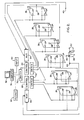
- FIG. 2 A schematic diagram of a system for measuring a stator half coil 11 with a substantially straight center section 16 and curved end sections 10 is illustrated in Fig. 2.
- the present invention utilizes a sonic digitizer, such as Model GP-83D from Scientific Accessories Corporation of Southport, Connecticut to obtain the location of points in space.
- a laser measurement system can be used if more precise measurements are required.
- the Model GP-83D has an accuracy of 0.01 cm (0.005 inch) and thus is able to provide sufficient accuracy for measuring stator half coils.
- a sonic digitizer like the Model GP-83D, uses a control unit 20 to control the generation of sparks by sparkers, e.g., Model LS-3DS, which act as sound emitters 22 and to time the receipt of the sounds generated by the sound emitters (sparkers) 22 at microphones 24.
- sparkers e.g., Model LS-3DS
- a calibration sparker 28 is controlled by the control unit 20 to periodically emit a sound from a fixed location so that the control unit 20 can compensate for the effects of changes in temperature and humidity on the speed of sound.
- the GB-83D sonic digitizer is limited to detecting sound in a cube having an edge length of nine feet. Since stator half coils 11 may be 11 m (36 ft.) long, more than one bank 26 of microphones 24 are required to measure a stator half coil 11. Therefore, in the preferred embodiment, several, e.g., six banks 26 of microphones 24 are arranged on a single plane and a pair of the control units 20 are supplemented by switches 30, 32 and multiplexers 34.
- the switch 30 is controlled by a computing apparatus 36, or manually, to select between the control units 20. Switches 32 are controlled so that the microphone banks 26 are sequentially activated one at a time.
- the multiplexers 34 output signals from the selected control unit 20 to the sound emitters 22, 28 in response to signals from the computing system 36.
- the sound emitters 22 are mounted on a sound emitter assembly 38 which is moved along the stator half coil 11 or other object to be measured, from one emission point to another. At an emission point, the sound emitters 22 received a signal from the multiplexer 34 and control unit 20 to generate sparks which cause sounds to be emitted by the sound emitters 22, one sound emitter 22 at a time in a predetermined sequence.
- the microphones 24 within the cube containing the sound emitter assembly 38 are activated by switch 32 prior to emission of the sounds by the sound emitters 22.
- the control unit 20 is able to detect the differences in the periods of time between emission of the sounds by the sound emitters 22 and receipt of the sounds by the microphones 24 in the one of the microphone banks 26 activated by the control unit 20 (or computing system 36 or manually) via switch 32. Due to limitations in cabling length, jacks 40 are provided for coupling the sound emitter assembly 38 for use with the banks 26 of microphones 24 connected to each of the control units 20.
- the microphones 24 are supported by a support structure 42a, 42b as illustrated in Figs. 3-5.
- the support structure is preferably continuous and only selected portions of the support structure 42a, 42b are illustrated in Figs. 3 and 4.
- the support structure 42a, 42b comprises a triangular truss as best illustrated in the end view provided in Fig. 5.
- the truss is formed of vertical struts 44, horizontal struts 46 and diagonal struts 48.
- Mounting surfaces 50 are provided for mounting the microphones 24 and are preferably aligned on a single plane to simplify the calculations which are necessary to combine measurements made by two different banks 26 of microphones 24.
- the portions 42a and 42a′ of the support structure which are illustrated in Figs. 3-5, are the ends of the support structure 42a, 42b, while portion 42b corresponds to the bank 26 third from the left in Fig. 2.
- the microphones 24 in banks 26 define overlapping rectangles so that measurements can be made of a single point by two banks 26 of microphones 24.
- the sound emitter assembly 38 is moved to a common position, approximately equidistant from two overlapping rectangles (banks 26) defined by eight of the microphones 24, while the microphones 24 defining one of the two overlapping banks 26 are activated and then activating the microphones 24 defining the other of the two overlapping banks 26 and generating the sounds again at the common position.
- the measurements made by the two banks 26 of microphones 24 are supplied by the control unit 20 to the computing apparatus 36.
- the computing apparatus 36 (Fig. 2) is programmed to convert the measurements made by the control units 20 of the emission points, including the common point and the calibration emission point 28, into corresponding surface points on the object at a known distance from the emission points.
- the distance between the emission and surface points is kept substantially constant by the sound emitter assembly 38 as described later.
- the surface points are combined by the computing apparatus 36 to define a measured shape.
- a representation of the measured shape is displayed on a display unit 52 simultaneously with a representation of the designed shape of the stator half coil 11 or other object.
- the designed and measured shapes are overlayed, one on top of the other, to aid in visually comparing the designed and measured shapes of the object.
- the display unit 52 is preferably a color display unit so that the measured and displayed shapes can be displayed in different colors.
- the computing apparatus 36 preferably includes CAD/CAM capability to more precisely measure variations between the designed and measured shapes using graphical measuring software.
- the surface points calculated by the computing apparatus 36 from the emission points measured by the control units 20 are connected as edges of the object and the display unit 52 displays at least two and preferably four edges of the object in each of the designed and measured shapes.
- a stator half coil 11 is essentially an elongated prism which has been bent at the ends 10. Like all prisms, a stator half coil 11 has a polygonal cross-section of substantially consistent size. The cross-section of a stator half coil 11 is typically rectangular. Thus, four edges of the designed and measured shapes of the object can be displayed on the display unit 52.
- a typical stator half coil 11 As noted in the description of a typical stator half coil 11 with reference to Fig. 1, the majority of the length of a stator half coil 11 is taken up by the straight center section 16. Ordinarily, during manufacturing the center section 16 of a stator half coil 11 is not bent and therefore, it is unnecessary to provide a bank 26 of microphones 24 for measuring the center section 16. Thus, as indicated in portion 42b of the support structure illustrated in Fig. 3, the banks 26 closest to the center of the supporting structure 42a, 42b need not overlap each other. As a result, there are two microphones 24 on the mounting surfaces 50 at the far left end of Fig. 3, but the mounting surfaces 50 to their right are each used by only a single microphone 24 to define the bank 26 fully illustrated in portion 42b.
- a stator half coil 11 of any length can be measured. Assuming the microphones in each bank are spaced approximately 2.4 m (8 ft.) apart (close to the maximum permitted with Model GP-83D), the entire length of a stator half coil 11 of less than approximately 7.3 m (24 ft.) can be measured by one of the sets of three overlapping banks 26. Longer stator half coils 11 can be supported at the center of the supporting structure 42a, 42b, with the center section 16 extending across the unmeasured region between the banks 26 closest to the center of the supporting structure 42a, 42b.
- any object that is no more than 2.4 m (8 ft.) high, 2.4 m (8 ft.) wide and 7.3 m (24 ft.) long can be measured by a set of three banks 26, the preferred embodiment is designed for measuring stator half coils 11. Therefore, as illustrated in Figs. 4 and 5, center brackets 53 on coil support pillars 54 are provided to support the center section 16 of the stator half coil 11. As illustrated in Fig. 5, roll around supports 56 are provided for supporting the ends 18 of the stator half coil 11. The roll around supports 56 are not illustrated in Figs. 3 and 4 to provide an unobstructed view of the support structure 42a, 42b and stator half coil 11.
- the roll around support 56 includes an end bracket 58 for supporting the end 18 of the stator half coil 11.
- the end bracket 58 includes a load cell for measuring the weight supported by the roll around support 56.
- the end bracket 58 is adjusted by a crank 60 until the load cell measures, e.g., 6.8 kg (15 lbs.). This provides repeatability of the measurements by steadying the stator half coil 11 during measurement so that vibration or other forces exerted on the stator half coil 11 do not cause undesirable fluctuations in the path of the sound emitter assembly 38.
- the sound emitter assembly 38 is moved along the surface of the curved end section 10 of the stator half coil or other object to be measured and sound is emitted at a number of emission points which are converted to surface points defining a measured shape of the object.
- the computing apparatus 36 In order for the computing apparatus 36 to calculate the relative positions of the object surface points in dependence upon periods of time between emission of the sounds by the sound emitters 22 and receipt of the sounds by one of the microphone banks 26, it is necessary for the computing apparatus 36 to know the distance between the sound emitters 22 and the surface of the object.
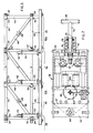
- this is accomplished by using a sound emitter assembly 38, such as that illustrated in Figs. 6 and 7.
- the sound emitter assembly 38 is preferivelyably a three-sided rectangular channel formed by sides 62, 64 and 66.
- the sound emitters (sparkers) 22 are mounted in a vertical plane on first side 62 and handle bracket 67 in cylinders 68.
- Stator half coils 11 have cross sections of varying sizes as indicated by cross sections 12 and 12′ in Fig. 6.
- an adjustable plate 70 is attached to a plate adjustment shaft 72 which is secured by pegs 74 which fit in slots 76, 80 in securing chamber 78 attached to first side 62.
- radial slots 76 are illustrated in cross-section, while in the front view of Fig. 6, axial slots 80 are indicated in the securing chamber 78 by dashed lines.
- a spring 82 couples the securing shaft 72 to the plate 70 so that stator half coils 11 of widths between those corresponding to the slots 76 can be accommodated.
- the securing shaft 72 is locked in place after putting tension on the spring 82 by twisting handle 83 to place pins 74 in a horizontal position in radial slots 76.
- other means such as threading the securing chamber 78 and shaft 70 and adding a lock nut or other locking means could also be used.
- rollers 84 are mounted inside the three-sided rectangular channel 62, 64, 66 on the plate 70 and sides 64 and 66. As best illustrated in Fig. 7, the preferred embodiment uses five rollers 84, two of which are mounted on the plate 70, two on the second side 64 and one on the third side 66.
- the rollers 84 preferably have an outer surface with a hardness of 70A durometer, which is provided by, e.g., polyurethane materials such as Duro 70A available from Parkway Products, Inc. in Cincinatti, Ohio.
- rollers 84 contact three of the four sides of the stator half coil and the adjustable plate 70 is positioned so that the roller 84, mounted on the third side 66, is held against side 86 of the stator coil 11 and the rollers 84, mounted on the second side 64, are held against side 88 of the stator half coil 11 by the weight of the sound emitter assembly 38.
- stator half coils are wrapped with tape which results in some irregularity in the surfaces.
- rollers with the surface hardness of between 50A and 70A durometer the rollers 84 are able to smooth perturbations of the sound emitter means caused by the irregular surfaces.
- the sound emitter assembly 38 is positioned on a stator half coil 11 having a cross-section 12 as illustrated in Fig. 6 with the securing shaft 72 secured by the securing chamber 80 so that there is a predetermined amount of spring tension in spring 82.
- precise measurements of the distance between the surfaces 86, 88 and the sound emitters 22 may be made, e.g., by an optical measurement system using lasers (not shown), when the sound emitter assembly 38 is used for the first time or if there is any reason to believe the measurements may have changed, e.g., due to wear in the rollers 84.
- the measurements between the sound emitters 22 and the surfaces of the stator half coil 11, together with the designed shape, including the measurements of cross-section 12, are input into the computing system 36 by an input unit 90 (Fig. 2), such as a keyboard or digitizer tablet.
- the results of the measurement may be output in addition to the display unit 52 to an output unit 92 such as a pen plotter, a CAD/CAM system or to a remote monitor or computer system.
- the sound emitter assembly 38 is moved along the stator half coil 11 by the use of handles 94 or by providing a motor (not shown) for driving one or more of the rollers 84, such as the roller 84 mounted on side 66.
- the control unit 20 sends signals to the four sparkers 22 and calibration sparker 28 to each emit a sound, resulting in four sounds a few milliseconds apart.
- the sounds may be emitted while the sound assembly 38 is moving or the assembly 38 may be stopped while the sounds are produced.
- the number of times that sounds are produced will depend upon how precisely measured a shape is desired.
- the banks 26 are sequentially activated as the sound emitter assembly 38 is moved from one emission point to another so that the rectangle defined by the activated one of the banks 26 of the microphones 24 contains an intersection point lying on a line perpendicular to the single plane of the mounting surfaces 50 and passing through a corresponding emission point at which the sound emitter apparatus 38 is positioned.
- a three-dimensional optical measurement system can be used, together with the computing apparatus 36 and display unit 52 so that a precisely measured shape of the object can be overlayed on the designed shape for comparison visually and by the computing apparatus 36 operating as a CAD/CAM system.
- the computing apparatus 36 operating as a CAD/CAM system.
- the sound emitter assembly 38 is shaped to match the shape of stator coils.
- a differently shaped sound emitter assembly could be used to measure other objects. Accordingly, all suitable modifications and equivalents may be resorted to falling within the scope and spirit of the invention.
Landscapes
- Physics & Mathematics (AREA)
- General Physics & Mathematics (AREA)
- Length Measuring Devices Characterised By Use Of Acoustic Means (AREA)
- Length Measuring Devices With Unspecified Measuring Means (AREA)
- Length Measuring Devices By Optical Means (AREA)
Applications Claiming Priority (2)
| Application Number | Priority Date | Filing Date | Title |
|---|---|---|---|
| US07/163,352 US4912663A (en) | 1988-03-02 | 1988-03-02 | Sonic digitizer coil measurement system |
| US163352 | 1988-03-02 |
Publications (2)
| Publication Number | Publication Date |
|---|---|
| EP0331445A2 true EP0331445A2 (de) | 1989-09-06 |
| EP0331445A3 EP0331445A3 (de) | 1990-05-30 |
Family
ID=22589654
Family Applications (1)
| Application Number | Title | Priority Date | Filing Date |
|---|---|---|---|
| EP89302001A Ceased EP0331445A3 (de) | 1988-03-02 | 1989-02-28 | Verfahren und Vorrichtung für ein digitales sonisches Messsystem für Spulen |
Country Status (5)
| Country | Link |
|---|---|
| US (1) | US4912663A (de) |
| EP (1) | EP0331445A3 (de) |
| JP (1) | JPH02145906A (de) |
| KR (1) | KR890015031A (de) |
| CN (1) | CN1036108A (de) |
Cited By (1)
| Publication number | Priority date | Publication date | Assignee | Title |
|---|---|---|---|---|
| WO1993004381A1 (en) * | 1991-08-15 | 1993-03-04 | Hein-Werner Corporation | Vehicle shape determination system |
Families Citing this family (5)
| Publication number | Priority date | Publication date | Assignee | Title |
|---|---|---|---|---|
| JPH0696100A (ja) * | 1992-09-09 | 1994-04-08 | Mitsubishi Electric Corp | 遠隔取引システム |
| JP3057960B2 (ja) * | 1993-06-22 | 2000-07-04 | トヨタ自動車株式会社 | 三次元形状加工物の評価装置 |
| US20020059177A1 (en) * | 2000-07-11 | 2002-05-16 | Paul Hansen | Method of forming a template and associated computer device and computer software program product |
| US7275300B2 (en) * | 2004-09-27 | 2007-10-02 | General Electric Company | Process for rapid on-demand stator rewinds in electrical generators |
| CN104043885B (zh) * | 2014-06-12 | 2016-06-08 | 上海理工大学 | 基于声发射技术表面白层去除方法 |
Family Cites Families (24)
| Publication number | Priority date | Publication date | Assignee | Title |
|---|---|---|---|---|
| US3176263A (en) * | 1960-08-19 | 1965-03-30 | Ellwood S Donglas | Measuring and recording method and apparatus |
| US3626483A (en) * | 1969-07-16 | 1971-12-07 | Science Accessories Corp | Spark pen |
| US4209853A (en) * | 1974-07-22 | 1980-06-24 | Hyatt Gilbert P | Holographic system for object location and identification |
| US3731273A (en) * | 1971-11-26 | 1973-05-01 | W Hunt | Position locating systems |
| JPS5519392B2 (de) * | 1973-07-25 | 1980-05-26 | ||
| US3985024A (en) * | 1975-02-28 | 1976-10-12 | Grumman Corporation | Acoustic emission process and system for improved flaw source location |
| US3981184A (en) * | 1975-05-07 | 1976-09-21 | Trw Inc. | Ultrasonic diagnostic inspection systems |
| US4012588A (en) * | 1975-08-29 | 1977-03-15 | Science Accessories Corporation | Position determining apparatus and transducer therefor |
| US4122525A (en) * | 1976-07-12 | 1978-10-24 | Eaton-Leonard Corporation | Method and apparatus for profile scanning |
| DE2643918C3 (de) * | 1976-09-29 | 1986-10-23 | Siemens AG, 1000 Berlin und 8000 München | Gerät zur Ultraschallabtastung |
| US4124838A (en) * | 1976-12-29 | 1978-11-07 | Science Accessories Corporation | Apparatus for position determination |
| GB1587712A (en) * | 1977-01-20 | 1981-04-08 | Structural Dynamics Ltd | Method and apparatus for determining marine riser shape |
| FR2379823A1 (fr) * | 1977-02-02 | 1978-09-01 | Inst Francais Du Petrole | Methode et dispositif pour determiner la configuration geometrique de la partie immergee des icebergs et leur tirant d'eau |
| US4099420A (en) * | 1977-06-03 | 1978-07-11 | Cornell Research Foundation, Inc. | Transducer positioning apparatus |
| US4332016A (en) * | 1979-01-26 | 1982-05-25 | A/S Tomra Systems | Method, apparatus and transducer for measurement of dimensions |
| US4357672A (en) * | 1980-07-30 | 1982-11-02 | Science Accessories Corporation | Distance ranging apparatus and method |
| JPS58115490A (ja) * | 1981-12-29 | 1983-07-09 | 日本電気株式会社 | パタン間距離計算装置 |
| US4528651A (en) * | 1983-02-04 | 1985-07-09 | Weyerhaeuser Company | Method and apparatus for measurement of length and height of objects |
| US4870623A (en) * | 1983-06-27 | 1989-09-26 | Cochlea Corporation | System to recognize a geometry parameter of unknown object with continuous wave acoustic energy |
| JPS61826A (ja) * | 1984-06-13 | 1986-01-06 | Fuji Xerox Co Ltd | 入力指示装置 |
| JPH061164B2 (ja) * | 1985-01-31 | 1994-01-05 | 伍良 松本 | 立体形状測定装置 |
| US4686639A (en) * | 1985-02-07 | 1987-08-11 | Rockwell International Corporation | Free space microscope digitizing aid |
| US4688430A (en) * | 1985-11-19 | 1987-08-25 | Anderson Forrest L | Device for imaging three dimensions with a single pulse transmission |
| FR2607244B1 (fr) * | 1986-11-20 | 1989-04-28 | Framatome Sa | Dispositif et methode de mesure de grille |
-
1988
- 1988-03-02 US US07/163,352 patent/US4912663A/en not_active Expired - Fee Related
-
1989
- 1989-02-28 EP EP89302001A patent/EP0331445A3/de not_active Ceased
- 1989-03-02 CN CN89101027A patent/CN1036108A/zh active Pending
- 1989-03-02 KR KR1019890002543A patent/KR890015031A/ko not_active Withdrawn
- 1989-03-02 JP JP1050969A patent/JPH02145906A/ja active Pending
Cited By (1)
| Publication number | Priority date | Publication date | Assignee | Title |
|---|---|---|---|---|
| WO1993004381A1 (en) * | 1991-08-15 | 1993-03-04 | Hein-Werner Corporation | Vehicle shape determination system |
Also Published As
| Publication number | Publication date |
|---|---|
| CN1036108A (zh) | 1989-10-04 |
| US4912663A (en) | 1990-03-27 |
| KR890015031A (ko) | 1989-10-28 |
| JPH02145906A (ja) | 1990-06-05 |
| EP0331445A3 (de) | 1990-05-30 |
Similar Documents
| Publication | Publication Date | Title |
|---|---|---|
| CA1266126A (en) | Deviation measurement system | |
| US8220167B2 (en) | Method of preparing a panel for fitting to a structure | |
| US4997283A (en) | Vehicle straightener measuring unit, measuring apparatus reliant on reflected beams, and source, targets and method | |
| JPH10508385A (ja) | 座標測定器用の校正装置 | |
| JPH0634356A (ja) | 簡易型三次元測定機、その移送用収納箱及びその各軸部材間の直角度調整方法 | |
| EP0331445A2 (de) | Verfahren und Vorrichtung für ein digitales sonisches Messsystem für Spulen | |
| JPS6488231A (en) | Glossiness measuring apparatus | |
| US5465214A (en) | Method of measuring the shape and/or the planarity of a running material, and device for its implementation | |
| JPH02138807A (ja) | 物体の横寸法測定方法およびその装置 | |
| JP3472897B2 (ja) | 線形測定装置及びこの装置を調整する方法 | |
| JPH07146128A (ja) | 環状領域計測装置 | |
| JP2008505328A (ja) | 複数の距離センサを有する測定装置、この測定装置のための校正手段および表面の形状を決定するための方法 | |
| JPH07239202A (ja) | 反り測定器 | |
| JPH1062117A (ja) | 三次元計測装置のレーザ式プローブ | |
| JPS5890109A (ja) | 多次元測定機の組立方法 | |
| JP4104652B2 (ja) | アナログおよびディジタルのディスプレイユニットを備えた測定装置 | |
| JP2849036B2 (ja) | コイル外径の測定方法およびその装置 | |
| JPH08122055A (ja) | 表面粗さ形状測定機のワーク傾斜調整方法及びその 装置 | |
| JPH06265685A (ja) | 燃料集合体の燃料棒位置測定方法及び装置 | |
| WO1992009863A1 (en) | Vehicle straightener measuring unit, measuring apparatus reliant on reflected beam(s), and source, targets and method | |
| JPH06185963A (ja) | 真直度測定装置 | |
| JP2598440B2 (ja) | 張力測定装置及び張力測定方法 | |
| JP2578153B2 (ja) | 断面測定装置 | |
| JPS6385311A (ja) | フラットネス測定装置 | |
| JPH10198428A (ja) | 移動体装置 |
Legal Events
| Date | Code | Title | Description |
|---|---|---|---|
| PUAI | Public reference made under article 153(3) epc to a published international application that has entered the european phase |
Free format text: ORIGINAL CODE: 0009012 |
|
| AK | Designated contracting states |
Kind code of ref document: A2 Designated state(s): BE DE ES FR IT |
|
| PUAL | Search report despatched |
Free format text: ORIGINAL CODE: 0009013 |
|
| AK | Designated contracting states |
Kind code of ref document: A3 Designated state(s): BE DE ES FR IT |
|
| 17P | Request for examination filed |
Effective date: 19901107 |
|
| 17Q | First examination report despatched |
Effective date: 19911203 |
|
| STAA | Information on the status of an ep patent application or granted ep patent |
Free format text: STATUS: THE APPLICATION HAS BEEN REFUSED |
|
| 18R | Application refused |
Effective date: 19920525 |