EP0331301A2 - Wendevorrichtung - Google Patents
Wendevorrichtung Download PDFInfo
- Publication number
- EP0331301A2 EP0331301A2 EP89301271A EP89301271A EP0331301A2 EP 0331301 A2 EP0331301 A2 EP 0331301A2 EP 89301271 A EP89301271 A EP 89301271A EP 89301271 A EP89301271 A EP 89301271A EP 0331301 A2 EP0331301 A2 EP 0331301A2
- Authority
- EP
- European Patent Office
- Prior art keywords
- mould
- inverter
- moulds
- carrier
- arcuate path
- Prior art date
- Legal status (The legal status is an assumption and is not a legal conclusion. Google has not performed a legal analysis and makes no representation as to the accuracy of the status listed.)
- Withdrawn
Links
- 239000011449 brick Substances 0.000 claims abstract description 23
- 230000035939 shock Effects 0.000 claims abstract description 13
- 230000000694 effects Effects 0.000 claims abstract description 5
- 239000000969 carrier Substances 0.000 claims description 12
- 239000004576 sand Substances 0.000 claims description 9
- 238000000576 coating method Methods 0.000 claims description 5
- 230000032258 transport Effects 0.000 claims description 5
- 239000011248 coating agent Substances 0.000 claims description 4
- 230000001186 cumulative effect Effects 0.000 claims description 2
- 208000037516 chromosome inversion disease Diseases 0.000 claims 4
- 238000001035 drying Methods 0.000 abstract description 5
- 238000005406 washing Methods 0.000 abstract description 3
- 238000000465 moulding Methods 0.000 description 6
- 239000011454 mudbrick Substances 0.000 description 5
- 230000009467 reduction Effects 0.000 description 3
- XLYOFNOQVPJJNP-UHFFFAOYSA-N water Substances O XLYOFNOQVPJJNP-UHFFFAOYSA-N 0.000 description 3
- 230000001133 acceleration Effects 0.000 description 2
- 238000004519 manufacturing process Methods 0.000 description 2
- 230000007246 mechanism Effects 0.000 description 2
- 235000008429 bread Nutrition 0.000 description 1
- 239000004927 clay Substances 0.000 description 1
- 230000002950 deficient Effects 0.000 description 1
- 238000010304 firing Methods 0.000 description 1
- 238000000034 method Methods 0.000 description 1
- 230000004048 modification Effects 0.000 description 1
- 238000012986 modification Methods 0.000 description 1
- 230000008569 process Effects 0.000 description 1
- 239000002023 wood Substances 0.000 description 1
Images
Classifications
-
- B—PERFORMING OPERATIONS; TRANSPORTING
- B28—WORKING CEMENT, CLAY, OR STONE
- B28B—SHAPING CLAY OR OTHER CERAMIC COMPOSITIONS; SHAPING SLAG; SHAPING MIXTURES CONTAINING CEMENTITIOUS MATERIAL, e.g. PLASTER
- B28B5/00—Producing shaped articles from the material in moulds or on moulding surfaces, carried or formed by, in or on conveyors irrespective of the manner of shaping
- B28B5/04—Producing shaped articles from the material in moulds or on moulding surfaces, carried or formed by, in or on conveyors irrespective of the manner of shaping in moulds moved in succession past one or more shaping stations
-
- B—PERFORMING OPERATIONS; TRANSPORTING
- B28—WORKING CEMENT, CLAY, OR STONE
- B28B—SHAPING CLAY OR OTHER CERAMIC COMPOSITIONS; SHAPING SLAG; SHAPING MIXTURES CONTAINING CEMENTITIOUS MATERIAL, e.g. PLASTER
- B28B17/00—Details of, or accessories for, apparatus for shaping the material; Auxiliary measures taken in connection with such shaping
Definitions
- This invention is concerned with improvements in or relating to an inverter and is particularly although not exclusively concerned with improvements in an inverter adapted for use in the inversion of moulds used in soft mud brick making.
- the moulds are cleaned by high pressure water jets and, after partial drying by an air blast or the like, the mould cavities are subjected to a sanding operation whereby the floor and walls of the mould cavities are each provided with a coating of sand.
- moulds used in soft mud brick manufacture are generally made of wood, wear is a major problem which may cause difficulties in feed arrangements for transposing the moulds from a downstream side of a moulding machine via an inverter to an input side of the moulding machine.
- the present invention thus conveniently provides an inverter adapted for use in a brick making machine comprisising a first carrier for transporting a mould through a first arcuate path, a second carrier for transporting a mould through a second arcuate path to cause inversion of the mould, characterised in that the inverter further comprises means for transferring a mould from the first to the second carrier whereby, when the inverter is in use, the cumulative effect of transporting a mould through said arcuate paths is to cause inversion of the mould without subjecting the mould to undue shock loads and to accurately locate the mould for subsequent operations thereon.
- the first and second carriers are mounted for arcuate movement about associated axes.
- the first and second carriers are provided on pairs of contra-rotating discs mounted for rotation about said axes.
- contra-rotating discs are provided with mutually intermeshing gears for ensuring, when the inverter is in use, that the pairs of discs are rotated in synchrony one with the other.
- the first carrier conveniently receives a mould at an in-feed position in which in-feed position the mould lies on an horizontal axis of said first arcuate path or substantially so and transfers it through said first arcuate path to a transfer position adjacent the second carrier whereat said transfer means is operated to effect the transfer of the mould from the first to the second carrier said transfer position being conveniently disposed on a common vertical axis of said first and second arcuate paths.
- the second carrier conveniently receives a mould from the transfer means at the transfer position and transports it through said second arcuate path to an outfeed position in which outfeed position the mould lies on an horizontal axis of said second arcuate path or substantially so whereby inversion of the mould is achieved as aforesaid.
- the horizontal axis of said first arcuate path lies below and is parallel or substantially so to the horizontal axis of said second arcuate path.
- first and second carriers arranged in associated pairs of first and second carriers and each carrier comprises clamping means for securing the moulds in the carrier.
- the present invention thus conveniently provides an inverter adapted for use in receiving an inverted sand coated mould from an infeed conveyor and, after inversion thereof, delivering the mould in a non-inverted condition to an infeed conveyor of a brick making machine in such a manner that the mould is accurately located with respect to the infeed conveyor and is not subjected to undue shock loads whereby the integrity of the sand coating is maintained.
- the inversion of brick making moulds in a soft mud brick making process is usually effected by rotary mechanisms and elevation devices which may be in combination therewith.
- the moulds are subjected to shock loads which may be most disadvantageous where sand coating of the mould cavities has been effected prior to inversion thereof.
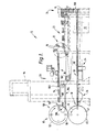
- the inverter 10 provided by the present invention seeks to overcome these drawbacks and is thus adapted for use in a brick making plant 12, see Figure 1, comprising a brick making machine 14 where moulds 16 are filled (by means not shown), an outfeed path 18 on the downstream side 20 of the machine 14 along which path the filled moulds 16 are conveyed firstly to an inversion device 22 and secondly to an associated conveyor 23 prior to discharge of the "green state" bricks 17 from moulds 16 at a discharge position 24, see Figure 1.
- the plant 12 also comprises an infeed conveyor 28 for transporting empty moulds 16 in their inverted condition from the discharge position 24 to an infeed position 30 of the inverter 10, see Figure 1.
- a mould washing device 32 Beneath the infeed conveyor 28 there are provided a mould washing device 32, a mould drying device 34 and a mould sanding device 36 all of conventional design which devices are only indicated in schematic outline in Figure 1.
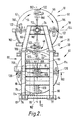
- the inverter 10 comprises a first carrier 40 provided by a pair of rotatable discs 42 arranged to receive moulds 16 seriatim from the infeed position 30 and to transport the moulds 16 through a first arcuate path indicated by the arrow 46 in Figures 1 and 2 to a transfer position 48, the inverter 10 also comprising a second carrier 50 provided by a pair of rotatable discs 52 arranged to receive moulds 16 seriatim from the first carrier 40 at said transfer position 48 and to transport the moulds 16 through a second arcuate path indicated by the arrows 56 in Figures 1 and 2 to an outfeed position 58 of the inverter 10, see Figure 1.
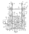
- the inverter 10 comprises a main frame 70 provided by two floor mounted side frames 72 and 74 joined towards their lower ends by two bridging members 76 and 77, see Figures 2 and 3.
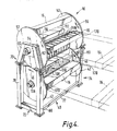
- the frames 72 and 74 are substantially the same with each comprising, see Figures 2, 3 and 4, spaced columns 78 and 80 supported at their lower ends on pads 82 and 84 respectively and bridged towards their upper ends by a member 86 and at mid portions thereof by a member 88, see Figure 2.
- the frames 72 and 74 also comprise inclined portions 90 and 92 extending upwardly from the columns 78 and 80 respectively to be joined by a bridging member 94 at their upper ends, see Figures 2 and 4.
- the pads 82 and 84 extend forwardly of the frame 72, that is to the left viewing Figure 3, and provide support for a subframe 100 on which is mounted a reduction gearbox and drive means 102 for rotating the discs 42 as described hereinafter.
- the columns 78 and 80 also provide support for further bridging elements 81 which in turn provide support for bearing brackets 106.
- the brackets 106 support a drive shaft 108 connected to the drive means 102.
- the shaft 108 thus extends between the frames 72 and 74 and carries the pair of rotatable discs 42 in spaced relationship as shown in Figures 3 and 4.
- the bridging members 94 each provide support for bearings 110 which in turn support a rotatable shaft 112.
- the shaft 112 thus extends between the frames 72 and 74 and carries the pair of rotatable discs 52 in spaced apart relationship as shown in Figures 3 and 4.
- the peripheries of the discs 42 and 52 adjacent the frame 72 are each provided with gear teeth 114 and 116 respectively which teeth are arranged in mutual engagement whereby, when the inverter is in use and shaft 108 is rotated by the drive means, rotation of the discs 42 causes corresponding rotation of the discs 52 in an opposite direction, i.e. the discs 42 and 52 are contra-rotating.
- the discs 42 provide support for four pairs of associated mould clamps 120, see Figures 2 and 3 and the discs 52 provide support for four pairs of associated mould clamps 122; the purpose and operation of the clamps 120 and 122 will become clear hereinafter.
- the inverter 10 further comprises a mould transfer device 130 fixedly mounted on the bridging elements 96 and 98, see Figures 2 and 3.
- the transfer device 130 comprises two columns 134 and 136, see Figures 2 and 3, which provide support for a cross-member 138 on a rearward face of which (viewing Figure 3) is provided aligned guides (not shown).
- the aligned guides engage side rails 144, of a bar 146 mounted for vertical movement beneath the transfer position 48 of the inverter 10.
- the bar 146 carries a pusher plate 150 at its upper end, see Figures 2 and 3, the purpose for which will be made clear hereinafter.
- the bar 146 carries a stud 147 on a lower front face thereof, which stud 147 is connected by a link 153 to a crank arm 156, see Figure 3.
- crank arm 156 is pivotally connected to a motor 159 via a reduction gearbox 157, operation of which motor 159 provides the power to cause vertical movement of the pusher plate 150 when the inverter 10 is in use.
- This form of drive for the pusher plate 150 is chosen to produce simple harmonic motion thereby ensuring controlled acceleration and deceleration of the pusher plate 150.
- the four pairs of clamps 120 and 122 are arranged at equi-spaced intervals about their respective discs 42 and 52.
- two pairs of clamps 120 each lie on a horizontal axis 160 and a common vertical axis 162 respectively of the discs 42 and two pairs of clamps 122 each lie on a horizontal axis 164 and the common vertical axis 162 respectively of the disc 52.
- the moulds 16 are fed through the machine 14 at a rate of 27 to 30 moulds per minute.
- Each mould has eight cavities 166.
- the moulds are fed seriatim by the outfeed conveyor 18 via the inversion device 22 where the moulds 16 are inverted to the discharge position where the mould cavities are emptied.
- the "green state" bricks 17 are then fed to a kiln car (not shown) and the moulds are transferred by a descending conveyor 168 to the infeed conveyor 28.
- each mould 16 When the moulds 16 reach the infeed position 30 they are pushed one at a time into the first carrier 42. To enable this, each mould 16 has side flanges 170 which locate between fixed and spring loaded jaws respectively of the clamps 120.
- the drive means 102 is operated to rotate the discs 42 in an anti-clockwise direction viewing Figures 1 and 2 to carry the mould 16 from its position coincident with the axis 160 and through the first arcuate path 46 to the transfer position 48 coincident with the common vertical axis 162 whereupon movement of the discs 42 is arrested.
- the drive means 102 is effective through a reduction gearbox, when the discs are rotated as aforesaid, to ensure that the mould 16 is moved with controlled acceleration and deceleration between controlled positions of dwell in which they are locked against further arcuate movement along said path 46.
- the transfer device 130 is then operated to elevate the pusher plate 150 via the piston, cylinder and crank arrangement whereupon the plate 150 engages the mould 16 arrested at the transfer position 48 to push it upwardly viewing Figures 2 and 3 from a position between the spring clamps 120 to a position between the juxtaposed clamps 122 of the carrier 50.
- the juxtaposed clamps 122 are thereafter operated to securely clamp the moulds in position.
- the clamps 122 are provided with fixed and movable jaws respectively with the movable jaw being movable by an associated piston and cylinder arrangement 180.
- the drive means 102 is again operated to rotate the discs 52 to carry the mould from the transfer position 48 coincident with the common vertical axis 162 through the second arcuate path 56 to the outfeed position 58 coincident with the axis 164 of the carrier 50 whereupon movement of the discs 52 is arrested.
- the drive means effects the same control on the mould 16 as it is carried through the second arcuate path 56 that was applied to the mould when it was carried through the first arcuate path 46.
- the inverter 10 also comprises two shield bars 182 (only one of which is shown in Figure 2) fixedly mounted one on each of the inclined portions 90 of the frames 72 and 74, which bars 182, when the inverter is in use, prevent moulds 16 carried by the carrier 52 from falling out of the clamps 122 should they prove defective, see Figure 2.
- the plant 12 also comprises an outfeed conveyor 186 which is arranged to partially underlie moulds 16 at the outfeed position 58 of the carrier 52.
- the conveyor 186 is driven by a motor 187 fixedly mounted on a frame of the brick making machine 14 which motor 187 also provides the drive for the conveyor 23 via appropriate chains and drive wheels as indicated in Figure 1.
- the conveyor 186 is provided with a series of eight pusher elements 188 which, when the plant is in use with a mould 16 located at the outfeed position 58, sequentially engage one at a time with a trailing edge portion 190 of an associated mould 16 to remove it from the carrier 50 and transport it towards the brick making machine 14.
- the inverter 10 of the present invention overcomes the drawbacks of known inverters and subjects the moulds to minimal shock loads. Also, the inverter is capable of accepting moulds of slightly different sizes and in transferring the moulds as aforesaid ensures, by operation of the transfer device 130, that the trailing edges 190 of the moulds are positioned at a common datum point at the outfeed position 58 so that the pusher elements 188 have a common pick-up and engagement point with respect thereto.
- the discs 42 and 52 are arranged to be contra-rotating, in an alternative embodiment provided by the invention the discs may be rotated in the same direction by any suitable gearing or like mechanism.
- the carriers 40 and 50 may be provided with more or less than the four pairs of mould clamps 120, e.g. there may be three or six such sets of clamps whereby in use the moulds 16 will be carried through longer or shorter arcuate paths and the transfer of the moulds between the carriers 40 and 50 will be effected at some angular position between the vertical and the horizontal axis of the first carrier 40.
- the carrier 50 will be offset from the vertical axis and will lie on a common transfer axis of the two carriers, e.g. where there are six sets of clamps 120, the common transfer axis will lie at 60° to the horizontal.
Landscapes
- Engineering & Computer Science (AREA)
- Chemical & Material Sciences (AREA)
- Ceramic Engineering (AREA)
- Mechanical Engineering (AREA)
- Manufacturing & Machinery (AREA)
- Attitude Control For Articles On Conveyors (AREA)
- Specific Conveyance Elements (AREA)
Applications Claiming Priority (2)
| Application Number | Priority Date | Filing Date | Title |
|---|---|---|---|
| GB888804775A GB8804775D0 (en) | 1988-03-01 | 1988-03-01 | Inverter |
| GB8804775 | 1988-03-01 |
Publications (2)
| Publication Number | Publication Date |
|---|---|
| EP0331301A2 true EP0331301A2 (de) | 1989-09-06 |
| EP0331301A3 EP0331301A3 (de) | 1991-06-12 |
Family
ID=10632594
Family Applications (1)
| Application Number | Title | Priority Date | Filing Date |
|---|---|---|---|
| EP19890301271 Withdrawn EP0331301A3 (de) | 1988-03-01 | 1989-02-10 | Wendevorrichtung |
Country Status (6)
| Country | Link |
|---|---|
| US (1) | US4936764A (de) |
| EP (1) | EP0331301A3 (de) |
| AU (1) | AU3071789A (de) |
| DK (1) | DK85189A (de) |
| GB (2) | GB8804775D0 (de) |
| ZA (1) | ZA891388B (de) |
Families Citing this family (2)
| Publication number | Priority date | Publication date | Assignee | Title |
|---|---|---|---|---|
| IT1282975B1 (it) * | 1996-05-09 | 1998-04-03 | Carle & Montanari Spa | Gruppo di smodellaggio per un impianto di modellaggio di cioccolato o prodotti simili |
| US6604342B1 (en) * | 2000-04-13 | 2003-08-12 | Paul Appelbaum | Method and apparatus for packaging articles in card and blister packages |
Family Cites Families (19)
| Publication number | Priority date | Publication date | Assignee | Title |
|---|---|---|---|---|
| USRE16424E (en) * | 1926-09-21 | Mold handling apparatus | ||
| US1452152A (en) * | 1918-09-05 | 1923-04-17 | Arnold Creager Company | Brickmaking apparatus |
| US1425449A (en) * | 1921-01-08 | 1922-08-08 | Edward D Cary | Mold-handling apparatus |
| US1597119A (en) * | 1924-09-08 | 1926-08-24 | David J Strickland | Brick-dumping apparatus |
| DE700476C (de) * | 1938-08-06 | 1940-12-20 | J M Lehmann Fa | Foerder- und Wendevorrichtung fuer Schokoladenformen |
| GB657576A (en) * | 1948-12-01 | 1951-09-19 | Purity Bakeries Service Corp | Improvements in or relating to a device for extracting bakery products from open top baking containers |
| US2664592A (en) * | 1951-09-14 | 1954-01-05 | Allied Chem & Dye Corp | Conveyer |
| US2827664A (en) * | 1952-10-08 | 1958-03-25 | Socony Mobil Oil Co Inc | Wax slabbing machine |
| GB1254861A (en) * | 1968-01-01 | 1971-11-24 | Tusker Engineering Company Ltd | Package handling equipment |
| GB1213224A (en) * | 1968-04-02 | 1970-11-25 | Guinness Son & Co Ltd A | Improvements in or relating to the handling of casks and the like |
| NL6916365A (de) * | 1969-10-30 | 1971-05-04 | ||
| US4006515A (en) * | 1974-12-10 | 1977-02-08 | The Procter & Gamble Company | Apparatus for forming tampons and assembling same in inserters |
| JPS6040368B2 (ja) * | 1978-04-24 | 1985-09-10 | 株式会社吉野工業所 | ピ−スの2軸延伸ブロ−成形機への供給装置 |
| DE3141364C2 (de) * | 1981-10-17 | 1984-12-20 | Krones Ag Hermann Kronseder Maschinenfabrik, 8402 Neutraubling | Vorrichtung zum Verteilen von aufrechtstehenden Gefäßen |
| US4793464A (en) * | 1983-03-14 | 1988-12-27 | F. J. Littell Machine Company | Apparatus for inverting strips of sheet material |
| JPS62259919A (ja) * | 1986-04-16 | 1987-11-12 | Kirin Brewery Co Ltd | 容器回転搬送装置 |
| US4832173A (en) * | 1985-05-31 | 1989-05-23 | Kirin Beer Kabushiki Kaisha | Device for rotating containers while transporting same |
| DD249681A1 (de) * | 1986-06-04 | 1987-09-16 | Nagema Veb K | Vorrichtung zum uebergeben von bonbons |
| IT1201605B (it) * | 1986-12-17 | 1989-02-02 | Gd Spa | Metodo e dispositivo per manipolare articoli |
-
1988
- 1988-03-01 GB GB888804775A patent/GB8804775D0/en active Pending
-
1989
- 1989-02-09 GB GB8902910A patent/GB2220185B/en not_active Expired - Fee Related
- 1989-02-10 EP EP19890301271 patent/EP0331301A3/de not_active Withdrawn
- 1989-02-21 US US07/313,067 patent/US4936764A/en not_active Expired - Fee Related
- 1989-02-23 ZA ZA891388A patent/ZA891388B/xx unknown
- 1989-02-23 DK DK085189A patent/DK85189A/da not_active Application Discontinuation
- 1989-02-24 AU AU30717/89A patent/AU3071789A/en not_active Abandoned
Also Published As
| Publication number | Publication date |
|---|---|
| EP0331301A3 (de) | 1991-06-12 |
| US4936764A (en) | 1990-06-26 |
| AU3071789A (en) | 1989-09-07 |
| GB2220185A (en) | 1990-01-04 |
| GB8804775D0 (en) | 1988-03-30 |
| DK85189D0 (da) | 1989-02-23 |
| DK85189A (da) | 1989-09-02 |
| GB8902910D0 (en) | 1989-03-30 |
| ZA891388B (en) | 1989-12-27 |
| GB2220185B (en) | 1991-11-20 |
Similar Documents
| Publication | Publication Date | Title |
|---|---|---|
| US4667804A (en) | Transfer apparatus for conveying work holder supports along a closed pathway | |
| EP0963929A1 (de) | Verfahren und Vorrichtung zum automatischen Laden einer Vielzahl von Artikeln angeordnet auf dieselbe Einheit einer Sortiermaschine mit Querband | |
| US3601266A (en) | Unloader blender | |
| US3801255A (en) | Automatic casting machine | |
| JP2735082B2 (ja) | ソーセージの搬送方法及び装置 | |
| US3648821A (en) | Workpiece transferring apparatus | |
| US4936764A (en) | Inverter for brick mould | |
| US3991885A (en) | Path control means for a swivel operated article transfer device | |
| GB2202207A (en) | Forming stacks of flat objects with non-uniform thickness | |
| US2501473A (en) | Article transfer mechanism for pallet conveyers | |
| JPH06329235A (ja) | 容器整列装置 | |
| JP3822758B2 (ja) | 列独立搬送部を備えた個別送り装置 | |
| US3075327A (en) | Method and apparatus for handling sheet or plates | |
| CN219906117U (zh) | 一种石墨坩埚装车推送装置 | |
| JPH09226722A (ja) | 袋詰め製品の集積装置 | |
| JP4350856B2 (ja) | 物品移載装置 | |
| CN113083692A (zh) | 一种仓储物流中心自动化分拣处理系统及分拣处理方法 | |
| JPS61205435A (ja) | 自動たこやき装置 | |
| US5361548A (en) | Multi-station abrading apparatus | |
| JPH07300115A (ja) | 長尺物箱詰め装置 | |
| GB2067511A (en) | Apparatus for varying the spacing between articles arranged in a series | |
| JP2805601B2 (ja) | 扱物反転装置 | |
| JP4294186B2 (ja) | 物品移載装置 | |
| CN222225161U (zh) | 用于热处理多用炉的摆料输送系统 | |
| JPH0314324Y2 (de) |
Legal Events
| Date | Code | Title | Description |
|---|---|---|---|
| PUAI | Public reference made under article 153(3) epc to a published international application that has entered the european phase |
Free format text: ORIGINAL CODE: 0009012 |
|
| AK | Designated contracting states |
Kind code of ref document: A2 Designated state(s): AT BE CH DE ES FR GB GR IT LI LU NL SE |
|
| PUAL | Search report despatched |
Free format text: ORIGINAL CODE: 0009013 |
|
| AK | Designated contracting states |
Kind code of ref document: A3 Designated state(s): AT BE CH DE ES FR GB GR IT LI LU NL SE |
|
| STAA | Information on the status of an ep patent application or granted ep patent |
Free format text: STATUS: THE APPLICATION IS DEEMED TO BE WITHDRAWN |
|
| 18D | Application deemed to be withdrawn |
Effective date: 19910829 |