EP0330890B1 - Anlage zur Sublimationstrocknung von Stoffen - Google Patents
Anlage zur Sublimationstrocknung von Stoffen Download PDFInfo
- Publication number
- EP0330890B1 EP0330890B1 EP89102398A EP89102398A EP0330890B1 EP 0330890 B1 EP0330890 B1 EP 0330890B1 EP 89102398 A EP89102398 A EP 89102398A EP 89102398 A EP89102398 A EP 89102398A EP 0330890 B1 EP0330890 B1 EP 0330890B1
- Authority
- EP
- European Patent Office
- Prior art keywords
- drying
- chamber
- condenser
- pressure plate
- drying chamber
- Prior art date
- Legal status (The legal status is an assumption and is not a legal conclusion. Google has not performed a legal analysis and makes no representation as to the accuracy of the status listed.)
- Expired - Lifetime
Links
- 238000001035 drying Methods 0.000 title claims description 52
- 238000000859 sublimation Methods 0.000 title claims description 4
- 230000008022 sublimation Effects 0.000 title claims description 4
- 238000006073 displacement reaction Methods 0.000 claims description 5
- 238000007789 sealing Methods 0.000 claims description 2
- 239000000126 substance Substances 0.000 description 15
- 238000010276 construction Methods 0.000 description 9
- 238000004108 freeze drying Methods 0.000 description 9
- XLYOFNOQVPJJNP-UHFFFAOYSA-N water Chemical compound O XLYOFNOQVPJJNP-UHFFFAOYSA-N 0.000 description 6
- 239000007787 solid Substances 0.000 description 4
- 238000004140 cleaning Methods 0.000 description 3
- 238000000034 method Methods 0.000 description 3
- 230000008569 process Effects 0.000 description 3
- 230000008901 benefit Effects 0.000 description 2
- 238000007689 inspection Methods 0.000 description 2
- 230000007246 mechanism Effects 0.000 description 2
- 238000005192 partition Methods 0.000 description 2
- 239000003507 refrigerant Substances 0.000 description 2
- 238000010257 thawing Methods 0.000 description 2
- 230000000712 assembly Effects 0.000 description 1
- 238000000429 assembly Methods 0.000 description 1
- 230000000903 blocking effect Effects 0.000 description 1
- 239000003990 capacitor Substances 0.000 description 1
- 238000009833 condensation Methods 0.000 description 1
- 230000005494 condensation Effects 0.000 description 1
- 230000001143 conditioned effect Effects 0.000 description 1
- 230000005496 eutectics Effects 0.000 description 1
- 230000008014 freezing Effects 0.000 description 1
- 238000007710 freezing Methods 0.000 description 1
- 230000003993 interaction Effects 0.000 description 1
- 238000012423 maintenance Methods 0.000 description 1
- 239000000203 mixture Substances 0.000 description 1
- 230000002093 peripheral effect Effects 0.000 description 1
- 238000001556 precipitation Methods 0.000 description 1
- 230000009467 reduction Effects 0.000 description 1
- 230000000284 resting effect Effects 0.000 description 1
- 238000004904 shortening Methods 0.000 description 1
- 238000003860 storage Methods 0.000 description 1
- 238000011179 visual inspection Methods 0.000 description 1
- 238000003466 welding Methods 0.000 description 1
Images
Classifications
-
- F—MECHANICAL ENGINEERING; LIGHTING; HEATING; WEAPONS; BLASTING
- F26—DRYING
- F26B—DRYING SOLID MATERIALS OR OBJECTS BY REMOVING LIQUID THEREFROM
- F26B5/00—Drying solid materials or objects by processes not involving the application of heat
- F26B5/04—Drying solid materials or objects by processes not involving the application of heat by evaporation or sublimation of moisture under reduced pressure, e.g. in a vacuum
- F26B5/06—Drying solid materials or objects by processes not involving the application of heat by evaporation or sublimation of moisture under reduced pressure, e.g. in a vacuum the process involving freezing
Definitions
- the invention relates to a system according to the preamble of claim 1.
- sublimation drying which is used for temperature-sensitive substances, for example in the pharmaceutical, biochemical and food industries
- the component of a substance to be separated by the drying process is in the solid or frozen state and is immediately converted into the vapor state.
- a drying chamber charged with the drying substance is connected via a connecting line containing a valve to a condenser chamber, which in turn is connected to an ice condenser connected to a refrigerator and a vacuum generator is connected.
- a condenser chamber which in turn is connected to an ice condenser connected to a refrigerator and a vacuum generator is connected.
- Such a system is known, for example, from the "Freeze drying systems" brochure from Martin Christ Freeze drying systems, 3360 Osterode.
- the possibility of separating the drying chamber from the condenser chamber provided by the valve serves to prevent vapors from entering the drying chamber during a defrosting process and to determine the end of drying over the course of the pressure increase.
- the valve When the valve is closed, the pressure in the drying chamber rises as long as there is still water vapor.
- a disadvantage of this known system is that the connecting line containing the valve forms a considerable narrowing of the flow cross section available for the removal of the sublimed vapors.
- the pressure loss caused by this affects on the one hand the drying time required to achieve a certain degree of drying and on the other hand limits the vacuum that can be achieved in the drying chamber.
- the complete sulbimation of a solution can only be carried out at temperatures below its respective eutectic temperature, namely the temperature of the maximum freezing point depression or the high vacuum corresponding to this.
- the drying substance is often inside the drying chamber in vessels or vials on which a so-called vacuum stopper is placed.
- the latter allows vapors to escape in the loosely attached state during the drying phase and to seal the vials in a vacuum-tight manner when firmly pressed in.
- Within the drying chamber there is a displaceably arranged pressure plate, which is that the displacement of the same in the same direction movable surfaces for the vial-carrying shelves are also moved, whereby this vial can be closed by their vacuum stopper at the end of the drying process to exclude any interactions between the dried substance and the environment.
- Another freeze drying system is known from DE-B-1185544, in which a drying chamber from a condenser chamber is known within a cylindrical jacket through a perforated bottom attached to the jacket.
- the jacket mentioned is located within a cylindrical container and can be moved relative to it in the axial direction.
- Inside the condenser chamber there is a good stand which is formed by setting plates which in turn are connected to the bottom area of the said container by means of bolts.
- the shelves serve as storage space for bottles that contain the items to be dried.
- the lower end of the good stand forms a plate, which is also provided with openings, the openings of which, however, are arranged offset with respect to that of the bottom mentioned, so that the bottom in connection with the latter plate enters the drying chamber of the Form the condenser chamber separating valve.
- the jacket and the bottom in order to actuate the valve, the jacket and the bottom must be moved in the axial direction of the outer container until the bottom and the plate come into contact with one another. Since the good stand is formed by a system of rigidly arranged, ie not movable relative to each other in the axial direction, the bottles located on these plates can not be closed by moving the plates. Since the aforementioned jacket must be moved with the floor in order to perform a valve function, the overall result is a comparatively complicated construction.
- the displacement mechanism formed by the aforementioned system of pressure plates and setting plates is functionally and structurally combined with the valve that blocks the condenser chamber from the drying chamber. All that is needed is a drive that simultaneously serves to actuate the valve and the aforementioned displacement mechanism.
- the pressure plate, which is present anyway, through which the system of setting plates is moved for the purpose of closing the vials mentioned, is thus given a further function, namely that of a moving valve part. This results in the possibility of practically extending the throughflow opening to be opened between the drying chamber and the condenser chamber to expand the dimensions of the condenser chamber, keeping pressure losses as low as possible and shortening the drying time.
- This double function of the pressure plate thus eliminates the need for a special valve and also gives the possibility of a compact construction of the system which requires little construction volume. Due to the high flow cross-section in the direction of the condenser chamber, there is also the possibility of a simple visual inspection of the interior of the condenser chamber and a good and flawless cleaning option. Since use is already made of existing structural parts for the constructive implementation of the valve function as far as possible, and the valve therefore does not constitute an additional component, this results in a very simple freeze-drying system which is also easy to handle, in particular from a maintenance point of view.
- claims 2 to 5 are directed to further advantageous construction variants which essentially aim at a small construction volume.
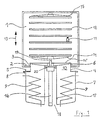
- FIG. 1 denotes a drying chamber, in the bottom area 2 of which an opening 3 is arranged.
- the drying chamber 1 is set up for discontinuous operation and is provided with a closable opening (not shown in the drawing) for introducing the drying substance or for removing the dried substance.
- a cylindrical component 4 projects into the opening 3 and has a flange 5 on one end facing away from the drying chamber and the other end of which is equipped with a circumferential seal 6, the meaning of which will be explained below.
- a condenser chamber 7 On the flange 5 is a condenser chamber 7, which carries a flange 8 at its upper end, for example by welding.
- the capacitor chamber 7 can be designed, for example, as a rotationally symmetrical vessel and is connected to a vacuum generator, not shown in the drawing.
- heat exchangers which function within the scope of the invention as ice condensers, so that a refrigerant flows within them.
- the ice condensers 9 are connected to a refrigerator, also not shown in the drawing. It can be seen from the previous illustration that the cylindrical Component 4 a connecting channel 10 is formed between the condenser chamber 7 on the one hand and the drying chamber on the other.
- the drying substance is accommodated in vials 11 which are sealed on the top side by a freeze-drying or vacuum stopper known per se.
- These stoppers have the property that steam can escape from the drying substance in the loosely attached state, but that in the pressed-in state of the stopper the vials 11 are closed in a vacuum-tight manner.
- the drying chamber 1 there are a number of positioning plates 12 which are arranged one above the other and are essentially identical to one another, which are inserted into a guide or displacement device (not shown in the drawing) and can be displaced in the direction of the arrows 13.
- Both printing plates have approximately the same dimensions.
- the movable pressure plate 14 serves to move the setting plates 12 in the direction of the arrows 13 and consequently cooperates with a special drive device 16.
- the drive devices 16, for example can consist of a piston-cylinder unit to which pressure medium can be applied on both sides, is arranged in a receiving tube 17 which extends coaxially to the condenser chamber 7.
- the receiving tube which is open at its lower end 18, is closed at its upper end by a closing plate 20, apart from a sealing bushing for a push rod 19.
- the push rod 19 is attached to the underside of the movable pressure plate 14, so that the pressure plate 14 can be moved in the direction of the arrows 13 by actuation of the drive device 16.
- the pressure plate 14 is drawn in an extended position and in a position 14 ', in which the connecting channel 10 is closed by the pressure plate 14 in connection with the circumferential seal 6. If the setting plates 12 do not carry vials 11, the pressure plate 14 can accordingly be extended until all the setting plates 12 are in contact with one another on the upper fixed pressure plate 15.
- the vials 11 containing the substance to be dried in solid form are placed on the setting plates 12 with loosely placed vacuum plugs, which for this purpose have been transferred to a corresponding spacing position from one another.
- the substance to be dried usually consists of a mixture of solid substances, one component of which is the substance to be sublimed. This component can be, for example, water in the frozen state.
- the vacuum generator not shown, is then used the vacuum corresponding to the sublimation pressure curve is set in the overall system, consisting of drying chamber 1 and condenser boiler 7, whereupon said solid substance evaporates out of the vial 11 and reaches the condenser chamber 7 via the connecting channel 10.
- the end of drying can be determined in a manner known per se by measuring the pressure curve in the drying chamber 1 after the connection channel 10 has been closed by means of the movable pressure plate 14. For reasons of clarity in the drawing, corresponding pressure measuring devices known per se have not been shown.
- the drive device 16 can be pushed into the vials 11 by pushing the setting plates 12 together, and thus a vacuum-tight closure of the latter can be achieved.
- the drive device 16 is in turn supported on a foundation 21 to which the lifting forces developed during its actuation are transmitted.
- a foundation 21 to which the lifting forces developed during its actuation are transmitted.
- any machine frame can also function as the foundation 21.
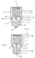
- the condenser chamber 7 is designed as a vessel which is essentially closed on the underside, the drive device 16 now being supported directly on the bottom 22 of the condenser chamber 7 at its end facing away from the pressure plate 14.
- the exemplary embodiment according to FIG. 4 is characterized in that the drive device 16 is now mounted on the top of the drying chamber 1 and interacts with a system of setting plates 12, which in turn are connected to one another by a guide linkage 23.
- the lower end of the system mentioned forms a pressure plate 24, which is in connection with the peripheral seal 6 attached to the above-mentioned upper edge of the condenser boiler 7, a valve function is assigned.
- the lower pressure plate 24 at the upper end opposite pressure plate 25 is attached directly to the tie rod 19 'of the drive device 16.
- the condenser chamber is designed as an essentially closed vessel, the upper, open end of which forms the connecting channel 10.
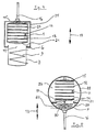
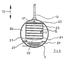
- drying chamber 1 and the condenser chamber 7 are designed as spatially separate or separable components.
- a drying chamber 26 and a condenser chamber 27 are accommodated within a common, here cylindrical vessel 28.
- the drying chamber and the condenser chamber are delimited by a partition 29 which is inserted into the vessel 28 and has an opening 30 in its central region.
- the drive device 16 is fastened in the lower region of the vessel 28, so that its push rods 19 are the condenser penetrates chamber 27.
- the drying chamber 26 there is a system of adjusting plates 12 corresponding to the exemplary embodiments in FIGS. 1 to 3, the lower pressure plate 14 of which is attached to the push rod 19 and, in connection with the opening 30 and the seal 31 surrounding it, fulfills a valve function.
- the pressure plate 15 opposite the pressure plate 14 at the upper end of the system is fixedly attached to the inner wall of the vessel 28.
- 5 corresponds to the exemplary embodiments of FIGS. 1 to 3, so that a repeated description is dispensed with.
- the drive device 16 is arranged on the upper region of the vessel 28, so that a linkage 23 according to the embodiment of FIG. 4 is provided, in which the adjusting plates 12 are guided.
- the link between the system of the setting plates 12 on the one hand and the drive device 16 on the other hand takes place via an upper pressure plate 25 which is attached to the tie rod 19 'of the drive device 16.
- a lower pressure plate 24, which can be lowered onto the opening 30 in the partition wall 29, takes over a valve function. Otherwise, the mode of operation and use of this system according to FIG. 6 corresponds to that according to FIG. 4.
Landscapes
- Engineering & Computer Science (AREA)
- Health & Medical Sciences (AREA)
- Life Sciences & Earth Sciences (AREA)
- Molecular Biology (AREA)
- Mechanical Engineering (AREA)
- General Engineering & Computer Science (AREA)
- Drying Of Solid Materials (AREA)
Applications Claiming Priority (2)
| Application Number | Priority Date | Filing Date | Title |
|---|---|---|---|
| DE3806299 | 1988-02-27 | ||
| DE3806299A DE3806299A1 (de) | 1988-02-27 | 1988-02-27 | Anlage zur sublimationstrocknung von stoffen |
Publications (3)
| Publication Number | Publication Date |
|---|---|
| EP0330890A2 EP0330890A2 (de) | 1989-09-06 |
| EP0330890A3 EP0330890A3 (en) | 1990-02-28 |
| EP0330890B1 true EP0330890B1 (de) | 1991-10-23 |
Family
ID=6348362
Family Applications (1)
| Application Number | Title | Priority Date | Filing Date |
|---|---|---|---|
| EP89102398A Expired - Lifetime EP0330890B1 (de) | 1988-02-27 | 1989-02-11 | Anlage zur Sublimationstrocknung von Stoffen |
Country Status (2)
| Country | Link |
|---|---|
| EP (1) | EP0330890B1 (enExample) |
| DE (2) | DE3806299A1 (enExample) |
Cited By (2)
| Publication number | Priority date | Publication date | Assignee | Title |
|---|---|---|---|---|
| DE202009009107U1 (de) | 2009-04-21 | 2009-10-01 | Martin Christ Gefriertrocknungsanlagen Gmbh | Anlage zur Gefriertrocknung von Stoffen |
| DE102009020563A1 (de) | 2009-04-21 | 2010-10-28 | Martin Christ Gefriertrocknungsanlagen Gmbh | Anlage zur Gefriertrocknung von Stoffen |
Families Citing this family (2)
| Publication number | Priority date | Publication date | Assignee | Title |
|---|---|---|---|---|
| AT1399U1 (de) * | 1995-11-29 | 1997-04-25 | Immuno Ag | Verfahren und einrichtung zum lyophilisieren |
| US6564471B1 (en) | 2001-03-12 | 2003-05-20 | S. P. Industries, Inc., The Virtis Division | Method and apparatus for freeze-drying |
Family Cites Families (5)
| Publication number | Priority date | Publication date | Assignee | Title |
|---|---|---|---|---|
| DE1185544B (de) * | 1963-05-10 | 1965-01-14 | Leybold Hockvakuum Anlagen G M | Mit gasfoermigem Kuehlmittel betriebene Gefriertrocknungskammer |
| DK117688B (da) * | 1965-03-18 | 1970-05-19 | Atlas As | Apparat til frysetørring af vandholdige produkter under vakuum. |
| DE1629143A1 (de) * | 1966-12-17 | 1971-01-21 | Wkf Ges Fuer Elektrophysikalis | Eiskondensator |
| US3451189A (en) * | 1967-04-14 | 1969-06-24 | Everett R Taggart | Desiccator apparatus including improved vacuum bottle capping arrangement |
| US3574950A (en) * | 1969-06-12 | 1971-04-13 | Jospeh L Dantoni | Lyophilizing apparatus |
-
1988
- 1988-02-27 DE DE3806299A patent/DE3806299A1/de active Granted
-
1989
- 1989-02-11 DE DE8989102398T patent/DE58900388D1/de not_active Expired - Lifetime
- 1989-02-11 EP EP89102398A patent/EP0330890B1/de not_active Expired - Lifetime
Non-Patent Citations (1)
| Title |
|---|
| "Gefriertrocknungsanlagen", Prospekt der Firma Martin Christ, Osterode * |
Cited By (3)
| Publication number | Priority date | Publication date | Assignee | Title |
|---|---|---|---|---|
| DE202009009107U1 (de) | 2009-04-21 | 2009-10-01 | Martin Christ Gefriertrocknungsanlagen Gmbh | Anlage zur Gefriertrocknung von Stoffen |
| DE102009020563A1 (de) | 2009-04-21 | 2010-10-28 | Martin Christ Gefriertrocknungsanlagen Gmbh | Anlage zur Gefriertrocknung von Stoffen |
| DE102009020563B4 (de) | 2009-04-21 | 2019-09-19 | Martin Christ Gefriertrocknungsanlagen Gmbh | Anlage zur Gefriertrocknung von Stoffen |
Also Published As
| Publication number | Publication date |
|---|---|
| EP0330890A3 (en) | 1990-02-28 |
| EP0330890A2 (de) | 1989-09-06 |
| DE3806299C2 (enExample) | 1990-03-08 |
| DE58900388D1 (de) | 1991-11-28 |
| DE3806299A1 (de) | 1989-09-07 |
Similar Documents
| Publication | Publication Date | Title |
|---|---|---|
| DE3425744C2 (enExample) | ||
| DE3320848C2 (enExample) | ||
| DE3003991C2 (de) | Kühleinrichtung mit einem Verdampfer, einem Kondersator sowie einem dehnbaren Flüssigkeitsbehälter | |
| EP0267935A1 (de) | Ventil für sterilisierbehälter und verfahren zum steueren des ventils. | |
| DE19726187C1 (de) | Vorrichtung zum Injizieren von Fluiden in Lebensmittel | |
| EP0330890B1 (de) | Anlage zur Sublimationstrocknung von Stoffen | |
| DE3311525C2 (enExample) | ||
| EP0002186B1 (de) | Druckaufschlussvorrichtung | |
| DE2942305A1 (de) | Kryopumpe und kryosammler zum aufsammeln von luftproben sowie angepasste schleusenvorrichtung | |
| DE2524771A1 (de) | Isostatische presse | |
| DE2856617C2 (de) | Beschickungsvorrichtung für einen unter Druck stehenden Behälter | |
| DE19818429C2 (de) | Gefriertrocknungsanlage | |
| DE2616369C2 (de) | Verfahren zum Trocknen von feuchtigkeitshaltigen Körpern | |
| EP0155407A2 (de) | Gasversorgungseinrichtung mit mehreren in einen Druckgasbehälter eingesetzten Gasflaschen | |
| DE1626220C2 (de) | Thermostatischer Kondenstopf | |
| DE2721618A1 (de) | Vorrichtung zum oeffnen und entleeren von koch-behaeltern fuer gegarten schinken | |
| EP0387250B1 (de) | Ventil für einen sterilisierbehälter | |
| EP0032718A1 (de) | Einrichtung zum Auffangen, Absaugen und Reinigen von auf der Koksseite einer Horizontalkammer-Verkokungsofenbatterie anfallenden Gasen | |
| DE2305803C3 (enExample) | ||
| DE2318030C3 (de) | Wärmeübertrager mit in einem vertikalen Kessel vertikal angeordneten Rohrbündel | |
| DE19544283C2 (de) | Gefriertrocknungsanlage | |
| DE2950048A1 (de) | Verfahren und vorrichtung zur energieerzeugung | |
| DE1526978A1 (de) | Druckdose fuer Kondenstopf sowie Verfahren und Vorrichtung zum Fuellen derselben | |
| DE9004857U1 (de) | Dissolver | |
| DE2208120B2 (de) | Vorrichtung zur Probenahme, insbesondere von Hackfruchten |
Legal Events
| Date | Code | Title | Description |
|---|---|---|---|
| PUAI | Public reference made under article 153(3) epc to a published international application that has entered the european phase |
Free format text: ORIGINAL CODE: 0009012 |
|
| AK | Designated contracting states |
Kind code of ref document: A2 Designated state(s): CH DE FR GB IT LI |
|
| PUAL | Search report despatched |
Free format text: ORIGINAL CODE: 0009013 |
|
| AK | Designated contracting states |
Kind code of ref document: A3 Designated state(s): CH DE FR GB IT LI |
|
| 17P | Request for examination filed |
Effective date: 19900821 |
|
| 17Q | First examination report despatched |
Effective date: 19910207 |
|
| GRAA | (expected) grant |
Free format text: ORIGINAL CODE: 0009210 |
|
| AK | Designated contracting states |
Kind code of ref document: B1 Designated state(s): CH DE FR GB IT LI |
|
| REF | Corresponds to: |
Ref document number: 58900388 Country of ref document: DE Date of ref document: 19911128 |
|
| ET | Fr: translation filed | ||
| ITF | It: translation for a ep patent filed | ||
| GBT | Gb: translation of ep patent filed (gb section 77(6)(a)/1977) | ||
| PLBE | No opposition filed within time limit |
Free format text: ORIGINAL CODE: 0009261 |
|
| STAA | Information on the status of an ep patent application or granted ep patent |
Free format text: STATUS: NO OPPOSITION FILED WITHIN TIME LIMIT |
|
| 26N | No opposition filed | ||
| PGFP | Annual fee paid to national office [announced via postgrant information from national office to epo] |
Ref country code: CH Payment date: 19980123 Year of fee payment: 10 |
|
| PGFP | Annual fee paid to national office [announced via postgrant information from national office to epo] |
Ref country code: GB Payment date: 19980202 Year of fee payment: 10 |
|
| PG25 | Lapsed in a contracting state [announced via postgrant information from national office to epo] |
Ref country code: GB Free format text: LAPSE BECAUSE OF NON-PAYMENT OF DUE FEES Effective date: 19990211 |
|
| PG25 | Lapsed in a contracting state [announced via postgrant information from national office to epo] |
Ref country code: CH Free format text: LAPSE BECAUSE OF NON-PAYMENT OF DUE FEES Effective date: 19990228 Ref country code: LI Free format text: LAPSE BECAUSE OF NON-PAYMENT OF DUE FEES Effective date: 19990228 |
|
| GBPC | Gb: european patent ceased through non-payment of renewal fee |
Effective date: 19990211 |
|
| REG | Reference to a national code |
Ref country code: CH Ref legal event code: PL |
|
| PG25 | Lapsed in a contracting state [announced via postgrant information from national office to epo] |
Ref country code: IT Free format text: LAPSE BECAUSE OF NON-PAYMENT OF DUE FEES;WARNING: LAPSES OF ITALIAN PATENTS WITH EFFECTIVE DATE BEFORE 2007 MAY HAVE OCCURRED AT ANY TIME BEFORE 2007. THE CORRECT EFFECTIVE DATE MAY BE DIFFERENT FROM THE ONE RECORDED. Effective date: 20050211 |
|
| PGFP | Annual fee paid to national office [announced via postgrant information from national office to epo] |
Ref country code: DE Payment date: 20080308 Year of fee payment: 20 |
|
| PGFP | Annual fee paid to national office [announced via postgrant information from national office to epo] |
Ref country code: FR Payment date: 20080219 Year of fee payment: 20 |