EP0329971B1 - Scheibenbremsgestänge mit Nachstellung - Google Patents
Scheibenbremsgestänge mit Nachstellung Download PDFInfo
- Publication number
- EP0329971B1 EP0329971B1 EP89101393A EP89101393A EP0329971B1 EP 0329971 B1 EP0329971 B1 EP 0329971B1 EP 89101393 A EP89101393 A EP 89101393A EP 89101393 A EP89101393 A EP 89101393A EP 0329971 B1 EP0329971 B1 EP 0329971B1
- Authority
- EP
- European Patent Office
- Prior art keywords
- brake
- adjustment
- lever
- linkage
- disc brake
- Prior art date
- Legal status (The legal status is an assumption and is not a legal conclusion. Google has not performed a legal analysis and makes no representation as to the accuracy of the status listed.)
- Expired - Lifetime
Links
- 238000010276 construction Methods 0.000 description 1
- 230000004048 modification Effects 0.000 description 1
- 238000012986 modification Methods 0.000 description 1
- 230000001960 triggered effect Effects 0.000 description 1
Images
Classifications
-
- B—PERFORMING OPERATIONS; TRANSPORTING
- B61—RAILWAYS
- B61H—BRAKES OR OTHER RETARDING DEVICES SPECIALLY ADAPTED FOR RAIL VEHICLES; ARRANGEMENT OR DISPOSITION THEREOF IN RAIL VEHICLES
- B61H15/00—Wear-compensating mechanisms, e.g. slack adjusters
-
- B—PERFORMING OPERATIONS; TRANSPORTING
- B61—RAILWAYS
- B61H—BRAKES OR OTHER RETARDING DEVICES SPECIALLY ADAPTED FOR RAIL VEHICLES; ARRANGEMENT OR DISPOSITION THEREOF IN RAIL VEHICLES
- B61H5/00—Applications or arrangements of brakes with substantially radial braking surfaces pressed together in axial direction, e.g. disc brakes
-
- F—MECHANICAL ENGINEERING; LIGHTING; HEATING; WEAPONS; BLASTING
- F16—ENGINEERING ELEMENTS AND UNITS; GENERAL MEASURES FOR PRODUCING AND MAINTAINING EFFECTIVE FUNCTIONING OF MACHINES OR INSTALLATIONS; THERMAL INSULATION IN GENERAL
- F16D—COUPLINGS FOR TRANSMITTING ROTATION; CLUTCHES; BRAKES
- F16D55/00—Brakes with substantially-radial braking surfaces pressed together in axial direction, e.g. disc brakes
- F16D55/02—Brakes with substantially-radial braking surfaces pressed together in axial direction, e.g. disc brakes with axially-movable discs or pads pressed against axially-located rotating members
- F16D55/22—Brakes with substantially-radial braking surfaces pressed together in axial direction, e.g. disc brakes with axially-movable discs or pads pressed against axially-located rotating members by clamping an axially-located rotating disc between movable braking members, e.g. movable brake discs or brake pads
- F16D55/224—Brakes with substantially-radial braking surfaces pressed together in axial direction, e.g. disc brakes with axially-movable discs or pads pressed against axially-located rotating members by clamping an axially-located rotating disc between movable braking members, e.g. movable brake discs or brake pads with a common actuating member for the braking members
- F16D55/2245—Brakes with substantially-radial braking surfaces pressed together in axial direction, e.g. disc brakes with axially-movable discs or pads pressed against axially-located rotating members by clamping an axially-located rotating disc between movable braking members, e.g. movable brake discs or brake pads with a common actuating member for the braking members in which the common actuating member acts on two levers carrying the braking members, e.g. tong-type brakes
Definitions
- the invention relates to a disc brake linkage for at least two adjacent brake discs with automatic adjustment of the air gap by means of a turnbuckle arranged in the brake linkage, the actuating cylinder for both brake discs being arranged on the brake caliper of a brake disc.
- a brake linkage for two brake shoes acting on the same wheel has become known from DE 27 29 6o6 C2, the actuating cylinder acting on the linkage of a brake shoe and an adjusting device being arranged in the main brake rod.
- the serious disadvantage of this device is that there are a very large number of connection and articulation points between the brake cylinder and the brake shoes, all of which are subject to wear and thus either require constant readjustment or cause too great uncertainty in the accuracy of the readjustment .
- the present invention is therefore based on the object of providing a brake linkage acting on two (or more) brake disks, with which the clearance for the brake shoes of both brake disks can be adjusted when using a single automatic adjusting device.
- the advantage of the construction according to the invention lies primarily in the fact that on the one hand the adjusting device is known per se and on the other hand it is nevertheless not very susceptible to wear due to the small number of connection points.
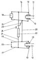
- two brake disks 11 and 12 are arranged on the same vehicle shaft (not shown).
- the brake shoes 13 are pressed against the friction surfaces of the brake discs 11 and 12 by a brake caliper in order to brake.
- Each brake pad is connected to a brake lever 14, 15, 16 and 17.
- An actuating cylinder 18 is arranged between the ends of the brake levers 14 and 15, which presses the two brake levers 14 and 15 apart under pressure.
- the other two brake levers 16 and 17 are connected at their ends by the rod 19. Both the actuating cylinder 18 and the connecting rod 19 are movably mounted on the vehicle or bogie frame.
- the inner brake levers 15 and 16 are connected to one another by the brake rod 20 and the two brake levers 14 and 17 are connected to one another by the rod 21.
- An automatic but known adjustment device 22 is arranged in the rod 21, by means of which the length of the rod 21 is changed as a function of the adjustment.
- an adjusting lever 23 is arranged on the brake lever 15 or on the brake lever 16 and cooperates with the adjusting mechanism of the adjusting device 22 when it has approached a certain dimension 24 of the device 22.
- the distance 24 between the adjusting lever 23 and the adjusting device 22 is reduced until the adjustment is triggered in a known manner, whereby the rod 21 is lengthened, so that the distance 24 between the adjusting device 22 and the adjusting lever 23 is increased again to the original dimension, at which the clearance of the brake shoes 13 is set correctly.
- the adjusting device 22 can thus be arranged on the rod 21 between two brake levers 14, 15 or 16, 17, wherein one of the brake levers 14-17 can be used as the adjusting lever 23.
- the adjusting device can also be arranged in the other connecting rod 2o, in which case the adjusting lever 23 is then arranged on the brake lever 14 or 17 which is not connected to the rod 2o.
Landscapes
- Engineering & Computer Science (AREA)
- Mechanical Engineering (AREA)
- General Engineering & Computer Science (AREA)
- Braking Arrangements (AREA)
Description
- Die Erfindung betrifft ein Scheibenbremsgestänge für mindestens zwei benachbarte Bremsscheiben mit automatischer Nachstellung des Lüftspiels mittels eines im Bremsgestänge angeordneten Spannschlosses, wobei der Betätigungszylinder für beide Bremsscheiben an der Bremszange einer Bremsscheibe angeordnet ist,
- Aus DE 27 29 6o6 C2 ist ein Bremsgestänge für zwei am gleichen Rad angreifende Bremsbacken bekannt geworden, wobei der Betätigungszylinder an dem Gestänge einer Bremsbacke angreift und eine Nachstellvorrichtung in der Hauptbremsstange angeordnet ist. Der gravierende Nachteil dieser Vorrichtung besteht darin, dass eine sehr grosse Anzahl Verbindungs- und Gelenkpunkte zwischen dem Bremszylinder und den Bremsbacken vorhanden sind, die alle dem Verschleiss unterworfen sind und dadurch entweder eine dauernde Nachstellung bedingen oder eine zu grosse Unsicherheit in die Genauigkeit der Nachstellung bringen.
- In einem anderen Fall (DE 17 8o 463 C2) werden die Bremszangen zweier auf der gleichen Achse angeordneter Bremsscheiben mit Gestängen miteinander verbunden, wobei in einer Verbindungsstange ein Spannschloss für die Nachstellung und der Betätigungszylinder am Drehgestell befestigt und mit einer Bremszange wirkverbunden ist, deren einer Bremshebel ebenfalls mit dem Drehgestell verbunden ist. Der Nachteil dieser Vorrichtung liegt darin, dass man in dieses Bremsgestänge keine selbsttätige Nachstellvorrichtung einsetzen kann, ohne erfinderisch tätig werden zu müssen.
- Der vorliegenden Erfindung liegt daher die Aufgabe zugrunde, ein auf zwei (oder mehr) Bremsscheiben wirkendes Bremsgestänge vorzusehen, mit dem bei Verwendung einer einzigen automatischen Nachstellvorrichtung das Lüftspiel für die Bremsbacken beider Bremsscheiben einstellbar ist.
- Die Lösung der Aufgabe besteht darin, dass zwischen je einem Bremshebel der beiden Gestänge eine an sich bekannte automatische Nachstellvorrichtung angeordnet ist und einer der anderen freien Bremshebel mit einem die an sich bekannte Nachstellvorrichtung steuernden Hebel verbunden ist.
- Der Vorteil der erfindungsgemässen Konstruktion liegt vor allem darin, dass einerseits die Nachstellvorrichtung an sich bekannt ist und andererseits trotzdem wegen der geringen Anzahl Verbindungspunkte wenig verschleissanfällig ist.
- Nach der Zeichnung, in der die Erfindung schematisch dargestellt ist, sind zwei Bremsscheiben 11 und 12 auf der gleichen Fahrzeugwelle (nicht dargestellt) angeordnet. Bei beiden Bremsscheiben werden von je einer Bremszange die Bremsbacken 13 an die Reibflächen der Bremsscheiben 11 und 12 gedrückt, um zu bremsen. Jeder Bremsbelag ist mit einem Bremshebel 14, 15, 16 und 17 verbunden. Zwischen den Enden der Bremshebel 14 und 15 ist ein Betätigungszylinder 18 angeordnet, welcher bei Druck die beiden Bremshebel 14 und 15 auseinander drückt. Die beiden anderen Bremshebel 16 und 17 sind an ihren Enden durch die Stange 19 miteinander verbunden. Sowohl der Betätigungszylinder 18 als auch die Verbindungsstange 19 sind beweglich am Fahrzeug- oder Drehgestellrahmen gelagert. Weiter sind die inneren Bremshebel 15 und 16 durch die Bremsstange 2o miteinander verbunden und die beiden Bremshebel 14 und 17 sind durch die Stange 21 miteinander verbunden. In der Stange 21 ist eine automatische aber an sich bekannte Nachstellvorrichtung 22 angeordnet, durch die die Länge der Stange 21 in Abhängigkeit von der Nachstellung verändert wird. Im Beispiel ist am Bremshebel 15 oder am Bremshebel 16 ein Nachstellhebel 23 angeordnet, der mit dem Nachstellmechanismus der Nachstellvorrichtung 22 zusammenwirkt, wenn er sich auf ein bestimmtes Mass 24 der Vorrichtung 22 genähert hat.
- Im dargestellten Beispiel wird bei grösserem Verschleiss an den vier Bremsbacken 13 oder auch nur an einer Bremsbacke 13 der Abstand 24 zwischen dem Nachstellhebel 23 und der Nachstellvorrichtung 22 solange verkleinert, bis die Nachstellung in bekannter Weise ausgelöst wird, wodurch die Stange 21 verlängert wird, sodass der Abstand 24 zwischen Nachstellvorrichtung 22 und Nachstellhebel 23 wieder auf das ursprüngliche Mass vergrössert wird, bei dem das Lüftspiel der Bremsbacken 13 richtig eingestellt ist.
- Es sind natürlich noch andere Konfigurationen und Modifikationen möglich, welche jedoch immer noch im Schutzbereich des Anspruchs liegen.
So kann die Nachstellvorrichtung 22 auf der Stange 21 zwischen zwei Bremshebeln 14,15 oder 16,17 angeordnet werden, wobei jeweils einer der Bremshebel 14 - 17 als Nachstellhebel 23 benutzt werden kann. Auch kann die Nachstellvorrichtung in der anderen Verbindungsstange 2o angeordnet sein, wobei dann der Nachstellhebel 23 an dem nicht mit der Stange 2o verbundenen Bremshebel 14 oder 17 angeordnet ist.
Claims (1)
- Scheibenbremsgestänge für mindestens zwei benachbarte Bremsscheiben mit automatischer Nachstellung des Lüftspiels mittels eines im Bremsgestänge angeordneten Spannschlosses, wobei der Betätigungszylinder für beide Bremsscheiben an der Bremszange einer Bremsscheibe angeordnet ist, dadurch gekennzeichnet, dass zwischen je einem Bremshebel (14,15,16,17) der beiden Gestänge (14,15 oder 16,17) eine an sich bekannte automatische Nachstellvorrichtung (22) angeordnet ist und einer der anderen freien Bremshebel mit einem die an sich bekannte Nachstellvorrichtung steuernden Nachstellhebel (23) verbunden ist.
Applications Claiming Priority (2)
| Application Number | Priority Date | Filing Date | Title |
|---|---|---|---|
| DE3805432 | 1988-02-22 | ||
| DE3805432A DE3805432A1 (de) | 1988-02-22 | 1988-02-22 | Scheibenbremsgestaenge mit nachstellung |
Publications (3)
| Publication Number | Publication Date |
|---|---|
| EP0329971A2 EP0329971A2 (de) | 1989-08-30 |
| EP0329971A3 EP0329971A3 (en) | 1990-01-24 |
| EP0329971B1 true EP0329971B1 (de) | 1994-09-14 |
Family
ID=6347871
Family Applications (1)
| Application Number | Title | Priority Date | Filing Date |
|---|---|---|---|
| EP89101393A Expired - Lifetime EP0329971B1 (de) | 1988-02-22 | 1989-01-27 | Scheibenbremsgestänge mit Nachstellung |
Country Status (3)
| Country | Link |
|---|---|
| EP (1) | EP0329971B1 (de) |
| AT (1) | ATE111403T1 (de) |
| DE (2) | DE3805432A1 (de) |
Families Citing this family (2)
| Publication number | Priority date | Publication date | Assignee | Title |
|---|---|---|---|---|
| DE4030659A1 (de) * | 1990-09-28 | 1992-04-02 | Linke Hofmann Busch | Bremseinrichtung fuer schienenfahrzeuge, insbesondere klotzbremse fuer drehgestelle, mit mindestens zwei gebremsten radsaetzen |
| EP0879751A1 (de) * | 1997-05-24 | 1998-11-25 | Powell Duffryn Standard Limited | Verbessertes Drehgestell für Schienenfahrzeuge |
Family Cites Families (2)
| Publication number | Priority date | Publication date | Assignee | Title |
|---|---|---|---|---|
| DE1780463C3 (de) * | 1968-09-18 | 1973-07-28 | Kloeckner Humboldt Deutz Ag | Gestaenge fuer Scheibenbremsen eines Radsatzes in Schienenfahrzeug-Drehgestellen |
| FR2294898A1 (fr) * | 1974-12-17 | 1976-07-16 | Sab Regleurs Freins | Ensemble de commande de dispositifs de freinage de vehicules ferroviaires |
-
1988
- 1988-02-22 DE DE3805432A patent/DE3805432A1/de not_active Withdrawn
-
1989
- 1989-01-27 EP EP89101393A patent/EP0329971B1/de not_active Expired - Lifetime
- 1989-01-27 DE DE58908334T patent/DE58908334D1/de not_active Expired - Fee Related
- 1989-01-27 AT AT89101393T patent/ATE111403T1/de not_active IP Right Cessation
Also Published As
| Publication number | Publication date |
|---|---|
| DE58908334D1 (de) | 1994-10-20 |
| DE3805432A1 (de) | 1989-08-31 |
| ATE111403T1 (de) | 1994-09-15 |
| EP0329971A3 (en) | 1990-01-24 |
| EP0329971A2 (de) | 1989-08-30 |
Similar Documents
| Publication | Publication Date | Title |
|---|---|---|
| DE69615770T2 (de) | Rotierender Träger mit Bremsscheiben, insbesondere zur Benutzung in Eisenbahnen | |
| EP0649992A1 (de) | Betätigungseinrichtung für eine Scheibenbremse | |
| DE2402469B2 (de) | Selbsttätige Nachstellvorrichtung für eine mechanisch betätigbare Teilbelag-Scheibenbremse, insbesondere Schwimmsattel-Scheibenbremse | |
| DE1922571A1 (de) | Scheibenbremse | |
| EP0659242B1 (de) | Druckluftbetätigte scheibenbremse | |
| DE69621032T2 (de) | Scheibenbremse für motorfahrzeug | |
| EP0015582B1 (de) | Bremseinrichtung für Schienenfahrzeuge | |
| DE2230949C3 (de) | Bremsbackenführung für eine Teilbelag-Scheibenbremse | |
| DE2346828A1 (de) | Nachstellvorrichtung fuer bremsen | |
| DE2309973C2 (de) | Bremsbetätigungsvorrichtung mit einem Betätigungshebel und veränderlicher Übersetzung | |
| DE4407293C1 (de) | Bremszange für Scheibenbremsen von Schienenfahrzeugen | |
| DE2261843B2 (de) | Selbsttaetige, doppeltwirkende bremsgestaengenachstelleinrichtung im bremsgestaenge, insbesondere von schienenfahrzeugen | |
| EP0381956A2 (de) | Klotzbremseinheit für Schienenfahrzeuge | |
| EP0137431B1 (de) | Klotzbremse für Schienenfahrzeuge | |
| EP0329971A2 (de) | Scheibenbremsgestänge mit Nachstellung | |
| DE1600085C3 (de) | Selbsttätige Nachstellvorrichtung für die Bremsbelagabnutzung einer Teilbelagscheibe | |
| DE2141430B2 (de) | Teilbelagscheibenbremse | |
| DE2449853C3 (de) | Scheibenbremse für Schienenfahrzeuge | |
| EP0267530B1 (de) | Bremseinrichtung für Schienenfahrzeuge, insbesondere Klotzbremse für mindestens zwei Radsätze | |
| DE2618966A1 (de) | Mechanische handbremseinrichtung fuer hydraulisch betaetigbare sattel- scheibenbremsen | |
| DE69415628T2 (de) | Scheibenbremse | |
| EP0753683A2 (de) | Scheibenbremse | |
| DE8802244U1 (de) | Scheibenbremsgestänge mit Nachstellung | |
| DE2817695A1 (de) | Scheibenbremse | |
| DE102023200745A1 (de) | Elektromechanische Bremse |
Legal Events
| Date | Code | Title | Description |
|---|---|---|---|
| PUAI | Public reference made under article 153(3) epc to a published international application that has entered the european phase |
Free format text: ORIGINAL CODE: 0009012 |
|
| AK | Designated contracting states |
Kind code of ref document: A2 Designated state(s): AT CH DE FR LI NL SE |
|
| PUAL | Search report despatched |
Free format text: ORIGINAL CODE: 0009013 |
|
| AK | Designated contracting states |
Kind code of ref document: A3 Designated state(s): AT CH DE FR LI NL SE |
|
| 17P | Request for examination filed |
Effective date: 19900712 |
|
| 17Q | First examination report despatched |
Effective date: 19930930 |
|
| GRAA | (expected) grant |
Free format text: ORIGINAL CODE: 0009210 |
|
| AK | Designated contracting states |
Kind code of ref document: B1 Designated state(s): AT CH DE FR LI NL SE |
|
| PG25 | Lapsed in a contracting state [announced via postgrant information from national office to epo] |
Ref country code: NL Effective date: 19940914 Ref country code: FR Effective date: 19940914 |
|
| REF | Corresponds to: |
Ref document number: 111403 Country of ref document: AT Date of ref document: 19940915 Kind code of ref document: T |
|
| REF | Corresponds to: |
Ref document number: 58908334 Country of ref document: DE Date of ref document: 19941020 |
|
| PG25 | Lapsed in a contracting state [announced via postgrant information from national office to epo] |
Ref country code: SE Effective date: 19941214 |
|
| PG25 | Lapsed in a contracting state [announced via postgrant information from national office to epo] |
Ref country code: AT Effective date: 19950127 |
|
| EN | Fr: translation not filed | ||
| NLV1 | Nl: lapsed or annulled due to failure to fulfill the requirements of art. 29p and 29m of the patents act | ||
| PLBE | No opposition filed within time limit |
Free format text: ORIGINAL CODE: 0009261 |
|
| STAA | Information on the status of an ep patent application or granted ep patent |
Free format text: STATUS: NO OPPOSITION FILED WITHIN TIME LIMIT |
|
| 26N | No opposition filed | ||
| PGFP | Annual fee paid to national office [announced via postgrant information from national office to epo] |
Ref country code: CH Payment date: 19970107 Year of fee payment: 9 |
|
| PGFP | Annual fee paid to national office [announced via postgrant information from national office to epo] |
Ref country code: DE Payment date: 19970221 Year of fee payment: 9 |
|
| PG25 | Lapsed in a contracting state [announced via postgrant information from national office to epo] |
Ref country code: LI Free format text: LAPSE BECAUSE OF NON-PAYMENT OF DUE FEES Effective date: 19980131 Ref country code: CH Free format text: LAPSE BECAUSE OF NON-PAYMENT OF DUE FEES Effective date: 19980131 |
|
| REG | Reference to a national code |
Ref country code: CH Ref legal event code: PL |
|
| PG25 | Lapsed in a contracting state [announced via postgrant information from national office to epo] |
Ref country code: DE Free format text: LAPSE BECAUSE OF NON-PAYMENT OF DUE FEES Effective date: 19981001 |