EP0329316A2 - Verfahren zum Herstellen von Fototaschen und so erhaltene Fototaschen - Google Patents
Verfahren zum Herstellen von Fototaschen und so erhaltene Fototaschen Download PDFInfo
- Publication number
- EP0329316A2 EP0329316A2 EP89301121A EP89301121A EP0329316A2 EP 0329316 A2 EP0329316 A2 EP 0329316A2 EP 89301121 A EP89301121 A EP 89301121A EP 89301121 A EP89301121 A EP 89301121A EP 0329316 A2 EP0329316 A2 EP 0329316A2
- Authority
- EP
- European Patent Office
- Prior art keywords
- web
- edge
- slide
- web section
- station
- Prior art date
- Legal status (The legal status is an assumption and is not a legal conclusion. Google has not performed a legal analysis and makes no representation as to the accuracy of the status listed.)
- Withdrawn
Links
- 239000000463 material Substances 0.000 title claims abstract description 102
- 238000003860 storage Methods 0.000 title claims abstract description 44
- 238000000034 method Methods 0.000 title claims description 19
- 238000004519 manufacturing process Methods 0.000 title claims description 15
- 238000010030 laminating Methods 0.000 claims abstract description 26
- 238000005520 cutting process Methods 0.000 claims abstract description 22
- 239000000853 adhesive Substances 0.000 claims abstract description 20
- 230000001070 adhesive effect Effects 0.000 claims abstract description 20
- 239000011230 binding agent Substances 0.000 claims abstract description 17
- 229920006254 polymer film Polymers 0.000 claims abstract description 12
- 230000001681 protective effect Effects 0.000 claims description 11
- 238000007789 sealing Methods 0.000 claims description 7
- 238000004804 winding Methods 0.000 claims description 3
- 238000005304 joining Methods 0.000 description 7
- 238000004049 embossing Methods 0.000 description 2
- 238000003466 welding Methods 0.000 description 2
- QTBSBXVTEAMEQO-UHFFFAOYSA-M Acetate Chemical compound CC([O-])=O QTBSBXVTEAMEQO-UHFFFAOYSA-M 0.000 description 1
- 239000003086 colorant Substances 0.000 description 1
- 238000003780 insertion Methods 0.000 description 1
- 230000037431 insertion Effects 0.000 description 1
- 239000005001 laminate film Substances 0.000 description 1
- 238000003475 lamination Methods 0.000 description 1
- 239000002184 metal Substances 0.000 description 1
Images




Classifications
-
- B—PERFORMING OPERATIONS; TRANSPORTING
- B42—BOOKBINDING; ALBUMS; FILES; SPECIAL PRINTED MATTER
- B42F—SHEETS TEMPORARILY ATTACHED TOGETHER; FILING APPLIANCES; FILE CARDS; INDEXING
- B42F11/00—Filing appliances with separate intermediate holding means
-
- B—PERFORMING OPERATIONS; TRANSPORTING
- B31—MAKING ARTICLES OF PAPER, CARDBOARD OR MATERIAL WORKED IN A MANNER ANALOGOUS TO PAPER; WORKING PAPER, CARDBOARD OR MATERIAL WORKED IN A MANNER ANALOGOUS TO PAPER
- B31B—MAKING CONTAINERS OF PAPER, CARDBOARD OR MATERIAL WORKED IN A MANNER ANALOGOUS TO PAPER
- B31B2150/00—Flexible containers made from sheets or blanks, e.g. from flattened tubes
- B31B2150/002—Flexible containers made from sheets or blanks, e.g. from flattened tubes by joining superimposed sheets, e.g. with separate bottom sheets
-
- B—PERFORMING OPERATIONS; TRANSPORTING
- B31—MAKING ARTICLES OF PAPER, CARDBOARD OR MATERIAL WORKED IN A MANNER ANALOGOUS TO PAPER; WORKING PAPER, CARDBOARD OR MATERIAL WORKED IN A MANNER ANALOGOUS TO PAPER
- B31B—MAKING CONTAINERS OF PAPER, CARDBOARD OR MATERIAL WORKED IN A MANNER ANALOGOUS TO PAPER
- B31B70/00—Making flexible containers, e.g. envelopes or bags
- B31B70/74—Auxiliary operations
- B31B70/92—Delivering
- B31B70/94—Delivering singly or in succession
- B31B70/946—Delivering singly or in succession the bags being interconnected
-
- Y—GENERAL TAGGING OF NEW TECHNOLOGICAL DEVELOPMENTS; GENERAL TAGGING OF CROSS-SECTIONAL TECHNOLOGIES SPANNING OVER SEVERAL SECTIONS OF THE IPC; TECHNICAL SUBJECTS COVERED BY FORMER USPC CROSS-REFERENCE ART COLLECTIONS [XRACs] AND DIGESTS
- Y10—TECHNICAL SUBJECTS COVERED BY FORMER USPC
- Y10T—TECHNICAL SUBJECTS COVERED BY FORMER US CLASSIFICATION
- Y10T156/00—Adhesive bonding and miscellaneous chemical manufacture
- Y10T156/10—Methods of surface bonding and/or assembly therefor
- Y10T156/1052—Methods of surface bonding and/or assembly therefor with cutting, punching, tearing or severing
- Y10T156/1056—Perforating lamina
-
- Y—GENERAL TAGGING OF NEW TECHNOLOGICAL DEVELOPMENTS; GENERAL TAGGING OF CROSS-SECTIONAL TECHNOLOGIES SPANNING OVER SEVERAL SECTIONS OF THE IPC; TECHNICAL SUBJECTS COVERED BY FORMER USPC CROSS-REFERENCE ART COLLECTIONS [XRACs] AND DIGESTS
- Y10—TECHNICAL SUBJECTS COVERED BY FORMER USPC
- Y10T—TECHNICAL SUBJECTS COVERED BY FORMER US CLASSIFICATION
- Y10T156/00—Adhesive bonding and miscellaneous chemical manufacture
- Y10T156/10—Methods of surface bonding and/or assembly therefor
- Y10T156/1052—Methods of surface bonding and/or assembly therefor with cutting, punching, tearing or severing
- Y10T156/1062—Prior to assembly
-
- Y—GENERAL TAGGING OF NEW TECHNOLOGICAL DEVELOPMENTS; GENERAL TAGGING OF CROSS-SECTIONAL TECHNOLOGIES SPANNING OVER SEVERAL SECTIONS OF THE IPC; TECHNICAL SUBJECTS COVERED BY FORMER USPC CROSS-REFERENCE ART COLLECTIONS [XRACs] AND DIGESTS
- Y10—TECHNICAL SUBJECTS COVERED BY FORMER USPC
- Y10T—TECHNICAL SUBJECTS COVERED BY FORMER US CLASSIFICATION
- Y10T156/00—Adhesive bonding and miscellaneous chemical manufacture
- Y10T156/10—Methods of surface bonding and/or assembly therefor
- Y10T156/1052—Methods of surface bonding and/or assembly therefor with cutting, punching, tearing or severing
- Y10T156/1084—Methods of surface bonding and/or assembly therefor with cutting, punching, tearing or severing of continuous or running length bonded web
- Y10T156/1085—One web only
Definitions
- the present invention relates generally to photograph slide sleeving material.
- the present invention is a method for manufacturing photograph slide sleeving material and slide storage files therefrom.
- Slide sleeves in the form of acetate or clear plastic pages with pockets are commonly used to store photograph slides. These pages are typically 8 ⁇ 1/2 by 11 inches in size and include five rows of four pockets. Twenty 35 mm photograph slides can therefore be stored on a page. One edge of the page is generally adapted to be inserted in a ring binder or suspended from a hanging file. Manufacturers of slide sleeving pages of the types described above include Photo Plastic Products, Inc., Pacific Foto Supply Company, Plastican Corp., Vue-All, Inc., and Picture Pocket Corp.
- Slide sleeve pages of these types appear to be individually manufactured following a sequence of steps.
- a main back sheet of polymer film material which is typically clear is first laid down. Five individual strips having a width of approximately 1 ⁇ 7/8 inches are then pulled across the sheet in a transverse direction. The individual strips are then laminated to the main back sheet at locations forming pocket bottom and side walls. The lamination appears to be done by welding or heat sealing. The page is then cut from the main back sheet.
- Photograph slides must also be manually inserted into the pockets of these photograph pages.
- the present invention is a method for manufacturing photograph slide sleeving material.
- a continuously moving first web section of polymer film material is provided to a cutting station. Pocket opening slots are cut in the first web section of film material as it moves past the cutting station, thereby forming a slotted first web section of film material.
- the slotted first web section of film material is continuously moved to a laminating station.
- a continuously moving second web section of polymer film material is also provided to the laminating station.
- the slotted first web section of film material and the second web section of film material are laminated to form pocket bottom walls and side walls while they move past the laminating station.
- a web of slide sleeving material having pockets formed therein emerges from the laminating station.
- the first and second web sections of film material are provided from rolls of film material.
- the first and second web sections of film material are laminated by heat sealing at locations forming the pocket side walls and bottom walls.
- the web of slide sleeving material can be perforated as it moves past a perforating station, and wound onto a take-up reel.
- Slide storage files can be formed by separating sheets of slide sleeving material from the web, and attaching hanging file or ring binder storage mounts by means of an adhesive strip.
- Slide sleeving material in accordance with the present invention can be produced at high speeds in a continuous web to keep costs down. Since this slide sleeving material is formed in a continuous web, it is also well suited for use with automatic photograph slide sleeving systems. Sections of the sleeving material which are loaded with photograph slides and torn from the web can be folded for compact storage, and packaged within envelopes commonly used in the photofinishing industry. Ring binder and hanging storage files can also be easily and inexpensively formed from the sleeving material.
- a roll 10 of slide sleeving material 12 fabricated in accordance with the present invention is illustrated generally in Figure 1, while a cross-section of a portion of the sleeving material is illustrated in Figure 2.
- sleeving material 12 is formed by a first polymer film web section 16A and a second polymer film web section 16B which are laminated together to form a geometric array of pockets 14.
- each pocket 14 is defined by a top wall 18, bottom wall 20, and a pair of side walls 22 and 24.
- Each pocket 14 also includes a pocket opening slot 26.
- Other embodiments i.e., that shown in Figure 4) do not include top walls 18, but can be otherwise identical.
- Rows of perforations 28 separate adjacent rows of pockets 14.
- Pockets 14 can be adapted to hold standard 35 mm photograph slides.
- Bottom wall 20 and top wall 18 of pockets 14 are formed by joining first film web section 16A to second film 16B at the desired locations.
- Film web sections 16A and 16B are laminated by intermittant heat seals in the illustrated embodiment.
- Top walls 18 and bottom walls 20 of pockets 14 in a given row are formed by intermittent or broken heat seals which extend linearly between edges 30 and 32 of sleeving material 12.
- Side walls 22 and 24 of pockets 14 of adjacent rows are formed by broken heat seals which extend linearly about a longitudinal axis of sleeving material 12, perpendicular to edges 30 and 32.
- Other methods such as continuous (unbroken) heat seals or ultrasonic welding can also be used to laminate film web sections 16A and 16B.
- Slots 26 of a given row of pockets 14 are parallel to bottom walls 20, separate from one another, and extend between side walls 22 and 24 of the respective pocket. Pocket opening slots 26 can be cut through first web section 16A before it is laminated to second web section 16B.
- Sleeving material 12 includes parallel rows of three pockets 14 in the embodiment shown.
- sleeving material 12 is 7.440 inches wide.
- Each pocket 14 can be 2.063 inches wide (i.e. the distance between its side walls 22 and 24).
- Pockets 14 are separated from one another along the transverse direction parallel to perforations 28 by .250 inches (i.e. the distance between side wall 24 of one pocket 14 and side wall 22 of an adjacent pocket).
- Side walls 24 of pockets 14 adjacent first edge 30 are separated from the edge by a distance of .500 inches.
- Side wall 22 of pocket 14 adjacent second edge 32 are spaced from the edge by .251 inches.
- Slots 26 of pockets 14 can be separated from corresponding bottom walls 20 by 2.190 inches.
- Perforation rows 28 can be spaced from one another by 2.375 inches, and rows of pockets 14 centered therebetween.
- web sections 16A and 16B are 1.65 mil. thick films of clear Crown Zeelon 339. This material is commercially available from Crown Zellerbach.
- one of web sections 16A and 16B is clear, while the other is matte. Other materials and colors can also be used.
- Sleeving material 12 having pockets 14 with the dimensions described above can firmly hold standard two inch by two inch 35 mm photograph slides, yet permit automatic insertion by machine.
- a flat package of photograph slides having a dimension of just over four by six inches is formed. These packaged photograph slides can fit into standard photofinishing envelopes used for returning four by six inch prints.
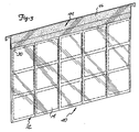
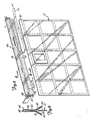
- Slide storage files such as hanging file 40 ( Figure 3) and ring binder file 42 ( Figure 4) can be assembled from sheets of sleeving material 12 which have been separated from roll 10.
- Hanging file 40 is formed by attaching a hanging file storage mount 44 to edge 30 of a five row section of sleeving material 12.
- hanging file storage mount 44 is formed by a mounting member 46 which is affixed to a hanger 48.
- Hangers such as 48 are commercially available and are generally formed from lightweight metal.
- Mounting member 46 can be fabricated from cardboard or any other desired material. Mounting member 46 can be secured to hanger 48 by folding it in half around the hanger and fastening overlying portions together by adhesive 50.
- Two adjacent flaps 52 extend beyond the portions of mount 46 secured by adhesive 50. Strips of adhesive 54 with overlying protective covers 56 are applied to the inside facing surfaces of flaps 52. Hanging file 40 is assembled by removing protective covers 56 and affixing the surfaces of flaps 52 with adhesive 54 onto edge 30 of the sheet of slide sleeving material 12.
- ring binder file 42 is formed by a ring binder storage mount 60 and a four row section of slide sleeving material 12.
- Ring binder mount 60 is formed by a folded strip of cardboard or other material which has a plurality of spaced holes 62 punched therethrough. The spacing of holes 62 are such that mount 60 is adapted to be received by standard ring-type binders.
- a pair of adjacent flaps 64 opposite mount 60 from the fold have adhesive strips 66 with protective liners 68 applied to their facing inside surfaces.
- Ring binder file 42 is assembled by removing liners 68 from ring binder mount 60 and affixing the surfaces of flaps 64 with adhesive 66 to edge 30 of the sheet sleeving material 12.
- Web press 70 which can be used to manufacture slide sleeving material 12 in accordance with a first manufacturing method is illustrated generally in Figure 9.
- Web press 70 includes a take-up reel 72 which is driven by motor 74, a perforating station 76, a laminating station 78, a joining station 80 and pocket slot cutting station 82.
- the operation of motor 74 and stations 76, 78, 80 and 82 are controlled and coordinated by a drive control system 84.
- Drive control system 84 can be an electric or mechanical system.
- Perforating station 76 includes a perforating drum 86 and a support drum 90 which are positioned adjacent one another.
- Drum 86 has a plurality of rows of perforating blades 88 longitudinally positioned thereon.
- Laminating station 78 includes a support drum 92 and a heat sealing drum 94.
- Heat sealing drum 94 includes a plurality of embossing ridges 96 which extend from the exterior surface of the drum and are positioned in such a manner as to correspond to the desired dimensions of top walls 18, bottom walls 20, and side walls 22 and 24 of pockets 14.
- Drum 94 is heated by a heater 98.
- Joining station 80 includes adjacent drums 100 and 102.
- Slot cutting station 82 includes slot cutting drum 104 and support drum 106.
- Slot cutting drum 104 has a plurality of rows of slot cutting blades 108 longitudinally positioned thereon. Blades 108 are positioned on the outer surface of drum 104 so as to correspond to the dimensional relationships of slots 26 of pockets 14.
- First film web section 16A is provided from a film roll 110 which is mounted to spool 112.
- Second film web section 16B is provided from a second roll 114 which is mounted to spool 116.
- first web section 16A is sequentially fed through the gap between drums 104 and 106 of slot cutting station 82, the gap between drums 100 and 102 of joining station 80, the gap between drums 92 and 94 of laminating station 78, and the gap between drums 86 and 90 of perforating station 76, before being wound onto take-up reel 72.
- Second web section 16B is unwound from roll 114, and fed through the drums of stations 80, 78, and 76, adjacent web section 16A as shown, before being wound onto take-up reel 72.
- Motor 74 runs continuously during the manufacturing operation, winding fabricated sleeving material 12 onto take-up reel 72. As it passes through slot cutting station 82, three pocket opening slots 26 are cut through first web section 16A by blades 108. Slots 26 are linearly adjacent to one another in a transverse direction across web section 16A. Each newly cut row of slots 26 will be spaced from a previously cut row by predetermined dimensions such as those described above. After leaving slot cutting station 82, slotted web section 16A is brought into positional alignment adjacent web section 16B at joining station 80. Joined web sections 16A and 16B are then fed through laminating station 78.
- Web sections 16A and 16B are laminated together as they pass through laminating station 78.
- the laminating is performed by embossing ridges 96 on heat sealing drum 94.
- ridges 96 contact first web 16A, adjoining portions of web sections 16A and 16B which are adjacent the ridges are melted together. Since ridges 96 correspond to top walls 18, bottom wall 20 and side walls 22 and 24 of pockets 14, the respective walls of the pockets are formed as web sections 16A and 16B are laminated together.
- perforating station 76 After emerging from laminating station 78, laminated web sections 16A and 16B pass through perforating station 76. Perforating blades 88 of drum 86 will perforate or cut through portions of the laminated web between top walls 18 of pockets 14 in one row, and bottom walls 20 of pockets 14 in an adjacent row. Rows of pockets 14 can then be easily separated from one another.
- Drive control system 84 coordinates the rotation of drums 104, 94 and 86 with the rotation of motor 74 is such a manner that slots 26, walls 18, 20, 22 and 24, and perforations 28 are properly positioned with respect to one another to properly form sleeving material 12. As shown, completed sleeving material 12 is rolled onto take-up reel 72.
- Web press 120 which can be used to manufacture slide sleeving material 12 in accordance with a second method is illustrated generally in Figure 10. Many elements of web press 120 can be functionally identical to web press 70 described above, and are identified by identical reference numerals which have been primed. As shown, web press 120 includes a take-up reel 72′ and drive motor 74′, perforation station 76′, laminating station 78′, joining station 80′, and pocket slot cutting station 82′. Motor 74′ and stations 76′, 78′, 80′ and 82′ are all interfaced to drive control system 84′. A heater 98′ is also interfaced to drum 94′ of laminating station 78.
- Web press 120 is supplied with a single web 122 of polymer film material from a roll 124 which is mounted on spool 126. After leaving roll 124, web 122 is folded in half about a fold line 128, so as to form adjoining web sections 16A and 16B. After web 122 is folded, web section 16A is fed through pocket slot cutting station 82′ and subsequently joined together with web section 16B at joining station 80′.
- the operations performed by stations 76′, 78′, 80′ and 82′ are identical to those described above with reference to Figure 9. Following the manufacture of slide sleeving material 12 on web press 120, the sleeving material is wound onto take-up reel 72′.
- Web press 120′ is illustrated in Figure 11.
- Web press 120′ functions in a manner similar to that of web press 120 described with reference to Figure 10, and similar features are identified by identical reference numerals.
- the difference between web press 120′ and web press 120 is in the positioning of pocket slot cutting station 82′.
- pocket cutting station 82′ of web press 120′ is positioned to cut pockets in web 122 as it is unwound from roll 124 and before it is folded to form web sections 16A and 16B. All other functions of web press 120′ are identical to those described above with reference to press 120.
Landscapes
- Sheet Holders (AREA)
- Photographic Processing Devices Using Wet Methods (AREA)
Applications Claiming Priority (2)
| Application Number | Priority Date | Filing Date | Title |
|---|---|---|---|
| US07/158,243 US4911777A (en) | 1988-02-19 | 1988-02-19 | Method for manufacturing photograph slide sleeving material |
| US158243 | 1988-02-19 |
Publications (2)
| Publication Number | Publication Date |
|---|---|
| EP0329316A2 true EP0329316A2 (de) | 1989-08-23 |
| EP0329316A3 EP0329316A3 (de) | 1991-11-21 |
Family
ID=22567248
Family Applications (1)
| Application Number | Title | Priority Date | Filing Date |
|---|---|---|---|
| EP19890301121 Withdrawn EP0329316A3 (de) | 1988-02-19 | 1989-02-06 | Verfahren zum Herstellen von Fototaschen und so erhaltene Fototaschen |
Country Status (3)
| Country | Link |
|---|---|
| US (1) | US4911777A (de) |
| EP (1) | EP0329316A3 (de) |
| JP (1) | JPH01255597A (de) |
Cited By (5)
| Publication number | Priority date | Publication date | Assignee | Title |
|---|---|---|---|---|
| EP0562416A1 (de) * | 1992-03-24 | 1993-09-29 | MAX ROS S.a.s. DI ROSEAN S. & C. | Verfahren zur automatischen Herstellung von Fächern für Brieftaschen, Scheckhaltern, Kreditkartenhaltern und dergleichen, Vorrichtung zur Durchführung dieses Verfahrens und die so hergestellten Fächer |
| GB2281056A (en) * | 1993-08-16 | 1995-02-22 | Richard Mark Player | A support attachment for filing literary work in a ring binder or by suspension |
| WO1998016398A1 (es) * | 1996-10-11 | 1998-04-23 | Valentin Masa Alcorlo | Soporte de sujeccion, fijacion, encuadernacion y archivo |
| BE1010754A3 (nl) * | 1996-11-20 | 1999-01-05 | Heeren Joseph Marie Polycarpe | Element voor het aanbrengen van een voorwerp aan een bevestigingsmiddel en werkwijze voor het vervaardigen ervan. |
| ES2143900A1 (es) * | 1996-10-11 | 2000-05-16 | Masa Alcorlo Valentin | Soporte de sujecion, fijacion encuadernacion y archivo. |
Families Citing this family (30)
| Publication number | Priority date | Publication date | Assignee | Title |
|---|---|---|---|---|
| US6173529B1 (en) * | 1987-03-04 | 2001-01-16 | Malcolm Glen Kertz | Plant growing room |
| US6122861A (en) * | 1987-03-04 | 2000-09-26 | Kertz; Malcolm Glen | Plant growing room |
| US5511340A (en) * | 1987-03-04 | 1996-04-30 | Kertz; Malcolm G. | Plant growing room |
| FR2632610B3 (fr) * | 1988-06-10 | 1990-10-19 | Dupuy Eng Sa | Procede de fabrication de feuilles de recouvrement de fenetres de boites presentoirs pliables, fenetres ainsi realisees et boites d'emballage munies de telles fenetres |
| EP0598803B1 (de) * | 1991-08-12 | 1996-12-18 | Purcocks, Dale McPhee | Blätter mit reiter oder merkzeichen |
| JP2549340B2 (ja) * | 1993-02-01 | 1996-10-30 | スライデックス株式会社 | ファイルシート収納装置 |
| US5792297A (en) * | 1993-09-02 | 1998-08-11 | Avery Dennison Corporation | Method for printing on index divider sheet assemblies and the like |
| US5558454A (en) * | 1993-09-02 | 1996-09-24 | Avery Dennison Corporation | One-piece laser/ink jet printable divider which is folded over at the binding edge |
| US6004062A (en) * | 1993-09-02 | 1999-12-21 | Avery Dennison Corporation | Index divider sheet assembly and the like |
| US5743566A (en) * | 1993-09-02 | 1998-04-28 | Avery Dennison Corporation | Index divider sheet assembly and the like |
| CN1126326A (zh) * | 1994-01-28 | 1996-07-10 | 苏州康瑞照相器材有限公司 | 用于档存照相底片的保存袋及其制造方法 |
| US5483386A (en) * | 1994-05-16 | 1996-01-09 | The Stanley Works | Composite framed mirror and method for making same |
| US5415279A (en) * | 1994-08-15 | 1995-05-16 | Omaga Enterprises, Inc. | Sleeving device, kit, and method |
| US5683533A (en) * | 1995-02-10 | 1997-11-04 | The Procter & Gamble Company | Method for manufacturing side panels for disposable articles |
| US6039354A (en) * | 1996-03-07 | 2000-03-21 | Acco Brands, Inc. | Index sheet having a dual-side directly machine printable index tab portion and method of making the same |
| US5954445A (en) * | 1996-03-07 | 1999-09-21 | Acco Brands, Inc. | Directly machine printable index sheet |
| US5924812A (en) * | 1996-08-21 | 1999-07-20 | Acco Brands, Inc. | Printable index sheet |
| US5966852A (en) * | 1996-11-15 | 1999-10-19 | Acco Brands, Inc. | Directly machine printable index sheet having index tab portions |
| US7437994B1 (en) * | 2000-11-20 | 2008-10-21 | Stone Editions, Inc. | Adhesive hinge strips for printer paper |
| DE10324785A1 (de) * | 2003-05-31 | 2004-12-30 | Conteyor Multibag Systems N.V. | Verfahren zur Herstellung eines flexiblen Haltesystems |
| US20050230957A1 (en) * | 2004-04-16 | 2005-10-20 | Holmberg Thomas A | Photo album sheet |
| WO2007120650A2 (en) * | 2006-04-10 | 2007-10-25 | Graphic Packaging International, Inc. | Reinforced carton with reclosable lid |
| EP2117939A1 (de) | 2007-02-23 | 2009-11-18 | Graphic Packaging International, Inc. | Verstärkter karton und verfahren zur herstellung von karton-rohlingen |
| US20090233019A1 (en) * | 2008-03-11 | 2009-09-17 | Acco Brands Usa Llc | Partitioned laminating jacket |
| US20090290930A1 (en) * | 2008-05-22 | 2009-11-26 | Acco Brands Usa Llc | Sheet protector |
| EP2312929A2 (de) * | 2008-07-29 | 2011-04-27 | Conley Rose, P.C. | Pflanzenzuchtvorrichtung |
| US8916015B2 (en) * | 2011-12-21 | 2014-12-23 | Kimberly-Clark Worldwide, Inc. | Tampon method of manufacture |
| US9211216B2 (en) | 2012-06-29 | 2015-12-15 | Kimberly-Clark Worldwide, Inc. | Tampon method of manufacture |
| GB2538752A (en) * | 2015-05-27 | 2016-11-30 | Sirane Ltd | Method for manufacturing a bag |
| CN105799367A (zh) * | 2016-04-28 | 2016-07-27 | 赵夫超 | 一种不干胶证件照 |
Family Cites Families (16)
| Publication number | Priority date | Publication date | Assignee | Title |
|---|---|---|---|---|
| BE560830A (de) * | ||||
| FR977350A (fr) * | 1948-11-10 | 1951-03-30 | Despe | Bande perforée pour constitution de feuillets amovibles |
| US2565367A (en) * | 1949-11-23 | 1951-08-21 | Polaroid Corp | Method for forming image-receiving film for use in photography |
| CH395923A (de) * | 1960-11-14 | 1965-07-31 | Zippel Georg | Aufhängevorrichtung an einem Zeichnungsblatt |
| GB995328A (en) * | 1962-09-24 | 1965-06-16 | Esselte Herzogs Aktiebolag | Method for manufacturing insertion sheets for collections of stamps, labels and the like |
| US3254828A (en) * | 1963-12-18 | 1966-06-07 | Automated Packaging Corp | Flexible container strips |
| DE2102517A1 (de) * | 1971-01-20 | 1972-08-10 | Lumbeck, Bernd, 4320 Hattingen | Sammelmappe zur Aufnahme von flachem Sammelgut |
| US3735516A (en) * | 1972-04-06 | 1973-05-29 | Holes Webway Co | Pocketed album page |
| US4170081A (en) * | 1975-09-08 | 1979-10-09 | Kiejzik Paul A | Novel microfilm jacket |
| US4041846A (en) * | 1975-09-11 | 1977-08-16 | Automated Packaging Systems, Inc. | Method of making container strips |
| DE2606338A1 (de) * | 1976-02-18 | 1977-08-25 | Wichelhaus Fa Klaus | Aufnahmetasche |
| GB1594701A (en) * | 1977-04-21 | 1981-08-05 | Moore Business Forms Ltd | Continuous stationery assemblies |
| US4234086A (en) * | 1979-10-02 | 1980-11-18 | Dorton Howard E | Apparatus for handling soiled surgical sponges |
| DE3032016C2 (de) * | 1980-08-25 | 1982-12-09 | Leuchtturm Albenverlag Paul Koch KG, 2054 Geesthacht | Verfahren und Vorrichtung zur Herstellung von mit doppellagigen Einstecktaschen aus Folienmaterial beklebten Blättern |
| US4713136A (en) * | 1981-01-07 | 1987-12-15 | The Kendall Company | Method for making a sponge collecting device |
| US4462854A (en) * | 1983-09-21 | 1984-07-31 | William W. Holes | Process and apparatus for making a multi-pocketed album page |
-
1988
- 1988-02-19 US US07/158,243 patent/US4911777A/en not_active Expired - Lifetime
-
1989
- 1989-02-06 EP EP19890301121 patent/EP0329316A3/de not_active Withdrawn
- 1989-02-17 JP JP1036445A patent/JPH01255597A/ja active Pending
Cited By (5)
| Publication number | Priority date | Publication date | Assignee | Title |
|---|---|---|---|---|
| EP0562416A1 (de) * | 1992-03-24 | 1993-09-29 | MAX ROS S.a.s. DI ROSEAN S. & C. | Verfahren zur automatischen Herstellung von Fächern für Brieftaschen, Scheckhaltern, Kreditkartenhaltern und dergleichen, Vorrichtung zur Durchführung dieses Verfahrens und die so hergestellten Fächer |
| GB2281056A (en) * | 1993-08-16 | 1995-02-22 | Richard Mark Player | A support attachment for filing literary work in a ring binder or by suspension |
| WO1998016398A1 (es) * | 1996-10-11 | 1998-04-23 | Valentin Masa Alcorlo | Soporte de sujeccion, fijacion, encuadernacion y archivo |
| ES2143900A1 (es) * | 1996-10-11 | 2000-05-16 | Masa Alcorlo Valentin | Soporte de sujecion, fijacion encuadernacion y archivo. |
| BE1010754A3 (nl) * | 1996-11-20 | 1999-01-05 | Heeren Joseph Marie Polycarpe | Element voor het aanbrengen van een voorwerp aan een bevestigingsmiddel en werkwijze voor het vervaardigen ervan. |
Also Published As
| Publication number | Publication date |
|---|---|
| JPH01255597A (ja) | 1989-10-12 |
| US4911777A (en) | 1990-03-27 |
| EP0329316A3 (de) | 1991-11-21 |
Similar Documents
| Publication | Publication Date | Title |
|---|---|---|
| US4911777A (en) | Method for manufacturing photograph slide sleeving material | |
| EP0278663B1 (de) | Verfahren zum Formen von Polsterstücken | |
| EP0324764B1 (de) | Verfahren und apparat zur herstellung von etiketten | |
| US6153039A (en) | Card and method of making same | |
| EP0232054B1 (de) | Etiketten und ihre Fertigung | |
| US4540619A (en) | Thermally shrinkable labeling band | |
| US4690720A (en) | Method of manufacturing multilayer labels and apparatus therefor | |
| US4859083A (en) | Bag chain attached to computer paper | |
| WO2000059799A1 (en) | Connection tape for square hole punch carrier type taping and method of manufacturing connection tape | |
| GB2072133A (en) | Machine and method for producing weather-proof multi-leaf shipping forms | |
| US6287744B1 (en) | Method of and apparatus for manufacturing instant photography film unit | |
| JP2009061696A (ja) | アルバム製本方法及びアルバム製本装置 | |
| US20030175067A1 (en) | Web process for making a binder case | |
| EP0709217A1 (de) | Schablonendruckmaschine | |
| JPH0245267B2 (ja) | Kirokudeisukuyojaketsutonoseizoho | |
| JP3264736B2 (ja) | 積層型花包装用袋ならびにこれを製造する方法および装置 | |
| JP2546033B2 (ja) | アルバム用台紙の製造方法 | |
| JP2523072B2 (ja) | ファイリング用袋状シ―トの製造方法 | |
| EP0362762A2 (de) | Verfahren und Vorrichtung zum Schutz von photographischen Negativen | |
| WO1995020485A1 (en) | Sleeving material for film archiving and method of making | |
| JP3417815B2 (ja) | 画像焼き付け方法及び葉書付き写真プリントの製造方法 | |
| JPH0331342B2 (de) | ||
| JPS6140142A (ja) | 貼着袋体の製造装置 | |
| CA1125154A (en) | Prefabricated laminating packet with tab | |
| JPH04345897A (ja) | ポケットファイルとその製造方法 |
Legal Events
| Date | Code | Title | Description |
|---|---|---|---|
| PUAI | Public reference made under article 153(3) epc to a published international application that has entered the european phase |
Free format text: ORIGINAL CODE: 0009012 |
|
| AK | Designated contracting states |
Kind code of ref document: A2 Designated state(s): DE FR GB IT NL |
|
| PUAL | Search report despatched |
Free format text: ORIGINAL CODE: 0009013 |
|
| AK | Designated contracting states |
Kind code of ref document: A3 Designated state(s): DE FR GB IT NL |
|
| 17P | Request for examination filed |
Effective date: 19920520 |
|
| 17Q | First examination report despatched |
Effective date: 19931228 |
|
| STAA | Information on the status of an ep patent application or granted ep patent |
Free format text: STATUS: THE APPLICATION IS DEEMED TO BE WITHDRAWN |
|
| 18D | Application deemed to be withdrawn |
Effective date: 19940510 |