EP0328994B1 - Dispositif d'arrêt pour la fabrication d'un renforcement pour pneumatique - Google Patents
Dispositif d'arrêt pour la fabrication d'un renforcement pour pneumatique Download PDFInfo
- Publication number
- EP0328994B1 EP0328994B1 EP89102078A EP89102078A EP0328994B1 EP 0328994 B1 EP0328994 B1 EP 0328994B1 EP 89102078 A EP89102078 A EP 89102078A EP 89102078 A EP89102078 A EP 89102078A EP 0328994 B1 EP0328994 B1 EP 0328994B1
- Authority
- EP
- European Patent Office
- Prior art keywords
- jaws
- core
- wire
- cord
- movement
- Prior art date
- Legal status (The legal status is an assumption and is not a legal conclusion. Google has not performed a legal analysis and makes no representation as to the accuracy of the status listed.)
- Expired - Lifetime
Links
Images


Classifications
-
- D—TEXTILES; PAPER
- D02—YARNS; MECHANICAL FINISHING OF YARNS OR ROPES; WARPING OR BEAMING
- D02G—CRIMPING OR CURLING FIBRES, FILAMENTS, THREADS, OR YARNS; YARNS OR THREADS
- D02G3/00—Yarns or threads, e.g. fancy yarns; Processes or apparatus for the production thereof, not otherwise provided for
- D02G3/44—Yarns or threads characterised by the purpose for which they are designed
- D02G3/48—Tyre cords
-
- B—PERFORMING OPERATIONS; TRANSPORTING
- B29—WORKING OF PLASTICS; WORKING OF SUBSTANCES IN A PLASTIC STATE IN GENERAL
- B29D—PRODUCING PARTICULAR ARTICLES FROM PLASTICS OR FROM SUBSTANCES IN A PLASTIC STATE
- B29D30/00—Producing pneumatic or solid tyres or parts thereof
- B29D30/06—Pneumatic tyres or parts thereof (e.g. produced by casting, moulding, compression moulding, injection moulding, centrifugal casting)
- B29D30/08—Building tyres
- B29D30/34—Building tyres by jointly covering two bead-rings, located parallel to each other at a distance apart, with fabric or cord layers
-
- B—PERFORMING OPERATIONS; TRANSPORTING
- B29—WORKING OF PLASTICS; WORKING OF SUBSTANCES IN A PLASTIC STATE IN GENERAL
- B29D—PRODUCING PARTICULAR ARTICLES FROM PLASTICS OR FROM SUBSTANCES IN A PLASTIC STATE
- B29D30/00—Producing pneumatic or solid tyres or parts thereof
- B29D30/06—Pneumatic tyres or parts thereof (e.g. produced by casting, moulding, compression moulding, injection moulding, centrifugal casting)
- B29D30/08—Building tyres
- B29D30/10—Building tyres on round cores, i.e. the shape of the core is approximately identical with the shape of the completed tyre
- B29D30/16—Applying the layers; Guiding or stretching the layers during application
- B29D2030/1664—Details, accessories or auxiliary operations not provided for in the other subgroups of B29D30/00
- B29D2030/1685—Details, accessories or auxiliary operations not provided for in the other subgroups of B29D30/00 the layers being applied being already cut to the appropriate length, before the application step
Definitions
- the present invention relates to the manufacture of tires. More particularly, it relates to a stage in the manufacture of a reinforcement from a single wire, corresponding to the preamble of claim 1.
- the principle is described in EP-A-243 851.
- the reinforcement for a tire is produced by hooking a continuous wire to two circles of wire retaining means so that a cylinder is thus defined by a plurality of goers and returns from one restraint to another. Then, by an appropriate movement of the retaining means, the wires are folded over and around the core so that the reinforcement takes, or begins to take its final place in the tire. But before folding, you must have isolated the wire from the unwinding means. This is the role of a head, illustrated in FIGS. 12 and 12a of the aforementioned application, said head ensuring the bonding of the last section of wire laid, to the first section of wire laid.
- the present invention aims to eliminate the use of glue when the unwinding of the wire is stopped.
- the self-adhesive properties of the wire used are used on the layer of raw rubber with which the core has been previously coated.
- FIG. 1 shows the core 7 defining the shape of the interior surface of the tire to be manufactured. This core is coated with a layer of unvulcanized rubber.
- the wire 4 was introduced into the clamp 2 and was then hooked to the first retaining means 3 encountered by the rotary arm 5, the end of which has only been shown here so as not to unnecessarily overload the drawing.
- the segments 41 and 42 constitute the first section of wire 4 laid, according to the definition of the term section given in the aforementioned patent application in which one will find more details on the process and the apparatus for which the device of the present invention is used.
- the rotary arm 5 is stopped on the side opposite to the clamp 2 and the wire 4 is in two straight sections 41 + 42 and 43 + 44 stretched and slightly inclined relative to one another. the other, intersecting at a point 40.
- this point 40 is located substantially in the middle of the future tire, in the transverse direction. For this, an adequate advance can be given to the arm 5 or else a bar 50 can be actuated to move the wire 4.
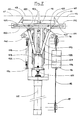
- the essential organ of the device is a pair of jaws 10 and 11. These jaws 10 and 11 are inserted on either side of this crossing point 40, on the one hand between the segment 41 of the wire 4 attached to the clamp 2 and the segment 43 hooked on the last retaining means 3 encountered by the arm 5, and on the other hand between the segment 44 joining the outlet orifice of the arm 5 and the segment 42 attached to the first retaining means 3 encountered by the arm at the start of this manufacturing phase.
- the device is designed and installed on the manufacturing apparatus so that the closing movement of the jaws is parallel to the axis of the core 7, that is to say approximately parallel to the bisector of the angle formed by the segments 41 and 43 of wire 4.
- the closing movement is shown diagrammatically in FIG. 1 by arrows in the vicinity of each of the jaws.
- a cutting system is implanted, constituted here very simply by a sharp blade 12 moving along the jaws 10 and 11.
- FIG. 7 gives in detail an embodiment of the control of the movement of the jaws 10 and 11 and of the blade 12.
- a first slide 123 controlled by a jack 122 and a light device, lug 124 and return spring 125 allows the 'introduction of the jaws 10 and 11 between the segments 41, 43 and 42, 44 of wire 4 (see Figure 1).
- the bases 100, 110 of the jaws 10 and 11 include lights 101 and 111 which make it possible to hold them on lugs 120 themselves fixed on the slide 123, while allowing a relative movement of approaching and moving the jaws 10 and 11 apart.
- Said relative movement is controlled by a toggle system, constituted by two links 105 and 115 each articulated on one of the bases 100, 110 on the one hand, and on a slide 126 integral with the head 121 of the jack 122.
- the extension of the jack 122 causes the opening of the V formed by the rods 105 and 115, and thus bringing the jaws 10 and 11 together.
- an additional extension of the jack 122 actuates the blade 12 by the fact that a lug 127 integral with the slide 126 abuts against the end of the light 128 arranged in the blade 12.
- the arrangement of the rods 105 and 115 is adjusted. so that the control of the blade 12 causes almost no movement of the jaws 10 and 11.
- the jaws 10 and 11 of the core 7 are approached, without loosening them so as to maintain the segments 42 and 43 of the wire 4 until these are applied to the unvulcanized rubber, capable of retain them by membership.
- the jaws accompany the movement imparted to the entire reinforcement by the retaining means 3.
- the jaws are released when a sufficient length of the segments 42 and 43 of wire 4 (start and end of laying of the reinforcement) is well applied to the core 7.
- the means used to ensure this approach include a counterweight 13, clearly visible in FIG. 5, which allows, as soon as the jaws 10 and 11 are in contact with the cylinder 45 of sections of wires 4, to accompany the decrease in diameter of the latter at the start of the folding phase on and around the core 7.
- the jaws 10 and 11 are carried by a structure 14 which slides on a guide slide 140.
- the approach and recoil movements of the structure 14 relative to the core 7 are controlled by means of a cable 15 wound around two return pulleys 16 and 17 whose axis is integral with the frame 141 of the machine.
- the cable 15 is hooked to the ends of the slide at 150 and 151.
- the movement of the cable 15 relative to the piston of the jack 18 is free in one direction but blocked by a stop 19 in the other direction.
- FIG. 5 shows the structure 14 in a position remote from the core 7. This is the position in which the jaws 10 and 11 pinch the wire 4.
- FIG. 6 shows the same structure 14 in the approximate position of the cylinder 45 of sections of wire 4.
- the advantage of the counterweight system 13 is that it makes it possible to follow the subsequent movement of the sections of wire 4 (which is explained in patent application EP 243 851 to which reference should be made for more details ), while maintaining a contact force in the light and constant radial direction.
Landscapes
- Engineering & Computer Science (AREA)
- Mechanical Engineering (AREA)
- Textile Engineering (AREA)
- Tyre Moulding (AREA)
- Ropes Or Cables (AREA)
- Tires In General (AREA)
- Arc Welding In General (AREA)
- Electrical Discharge Machining, Electrochemical Machining, And Combined Machining (AREA)
- Yarns And Mechanical Finishing Of Yarns Or Ropes (AREA)
- Moulding By Coating Moulds (AREA)
- Moulds For Moulding Plastics Or The Like (AREA)
Description
- La présente invention se rapporte à la fabrication des pneumatiques. Plus particulièrement, elle concerne un stade de la fabrication d'un renforcement à partir d'un seul fil, correspondant au préambule de la revendication 1. Le principe est décrit dans EP-A-243 851.
- Selon l'enseignement de cette demande de brevet, le renforcement pour pneumatique est réalisé par accrochage d'un fil continu à deux cercles de moyens de retenue du fil de sorte que l'on définisse ainsi un cylindre par une pluralité d'allers et de retours d'un moyen de retenue à un autre. Ensuite, par un mouvement approprié des moyens de retenue, on rabat les fils sur et autour du noyau pour que le renforcement prenne, ou commence à prendre sa place définitive dans le pneumatique. Mais avant de rabattre, il faut avoir isolé le fil des moyens de dévidage. C'est le rôle d'une tête, illustrée aux figures 12 et 12a de la demande précitée, ladite tête assurant le collage du dernier tronçon de fil posé, au premier tronçon de fil posé.
- La présente invention vise à supprimer l'emploi de colle lorsque l'on arrête le dévidage du fil. On utilise les propriétés d'auto-adhésion du fil utilisé sur la couche de caoutchouc cru dont le noyau a été préalablement revêtu.
- Le dispositif selon l'invention comporte:
- 1) deux mâchoires pouvant être insérées de part et d'autre des brins de fil à couper, puis pinçant le fil par un rapprochement de l'une vers l'autre dans un mouvement parallèle à l'axe dudit noyau,
- 2) un système de coupe du fil du côté des mâchoires opposé au noyau,
- 3) des moyens pour rapprocher lesdites mâchoires contre ledit noyau tout en les maintenant serrées.
- D'autres développements avantageux du dispositif selon la présente invention font l'object des revendications dépendantes.
- Les figures suivantes permettent de bien comprendre l'invention et d'en saisir tous les avantages.
- La figure 1 illustre la phase finale de l'accrochage du fil.
- La figure 2 est une vue en plan du dispositif.
- La figure 3 est une vue en élévation du dispositif.
- La figure 4 montre l'application du fil sur le noyau.
- Les figures 5 et 6 montrent la commande du mouvement d'approche du dispositif.
- La figure 7 fait apparaître la commande du mouvement des mâchoires.
- Bien sûr, le terme fil désigne ici en général tous les éléments filiformes utilisables pour construire ce que l'on désigne habituellement par nappe de carcasse ou nappe de sommet. On voit à la figure 1 le noyau 7 définissant la forme de la surface intérieure du pneumatique à fabriquer. Ce noyau est revêtu d'une couche de caoutchouc non vulcanisé. Au départ, le fil 4 a été introduit dans la pince 2 puis a été accroché au premier moyen de retenue 3 rencontré par le bras rotatif 5, dont on n'a représenté ici que l'extrémité pour ne pas surcharger inutilement le dessin. Les segments 41 et 42 constituent le premier tronçon de fil 4 posé, selon la définition du terme tronçon donnée dans la demande de brevet précitée dans laquelle on trouvera plus de détails sur le procédé et l'appareil pour lesquels le dispositif de la présente invention est utilisé. A la fin de cette phase de la fabrication, le bras rotatif 5 est arrêté du côté opposé à la pince 2 et le fil 4 se présente en deux tronçons 41 + 42 et 43 + 44 rectilignes tendus et faiblement inclinés l'un par rapport à l'autre, se croisant en un point 40. De préférence, on veille à ce que ce point 40 soit situé sensiblement au milieu du futur pneumatique, dans le sens transversal. Pour cela, on peut conférer une avance adéquate au bras 5 ou bien on peut actionner une barre 50 pour déplacer le fil 4.
- L'organe essentiel du dispositif est une paire de mâchoires 10 et 11. On insère cesdites mâchoires 10 et 11 de part et d'autre de ce point 40 de croisement, d'une part entre le segment 41 du fil 4 attaché à la pince 2 et le segment 43 accroché sur le dernier moyen de retenue 3 rencontré par le bras 5, et d'autre part entre le segment 44 rejoignant l'orifice de sortie du bras 5 et le segment 42 accroché au premier moyen de retenue 3 rencontré par le bras au départ de cette phase de fabrication. Le dispositif est conçu et implanté sur l'appareil de fabrication de sorte que le mouvement de fermeture des mâchoires est parallèle à l'axe du noyau 7, c'est-à-dire approximativement parallèle à la bissectrice de l'angle formé par les segments 41 et 43 de fil 4. Le mouvement de fermeture est schématisé sur la figure 1 par des flèches au voisinage de chacune des mâchoires.
- De la sorte, après fermeture des mâchoires 10 et 11 (figures 2 et 3), on trouve d'un côté de celles-ci (côté noyau 7), les segments 42 et 43 du fil 4 accrochés par ailleurs aux moyens de retenue 3, c'est-à-dire ceux devant faire partie du renforcement du pneumatique. De l'autre côté des mâchoires, on trouve les segments 41 et 44 rejoignant respectivement la pince 2 et le bras 5, c'est-à-dire ceux que l'on ne souhaite pas incorporer au renforcement.
- Du côté opposé au noyau 7, on implante un système de coupe, constitué ici très simplement par une lame tranchante 12 se déplaçant le long des mâchoires 10 et 11.
- La figure 7 donne en détails un exemple de réalisation de la commande du mouvement des mâchoires 10 et 11 et de la lame 12. Une première coulisse 123 commandée par un vérin 122 et un dispositif à lumière, ergot 124 et ressort 125 de rappel permet l'introduction des mâchoires 10 et 11 entre les segments 41, 43 et 42, 44 de fil 4 (voir figure 1). Les bases 100, 110 des mâchoires 10 et 11 comportent des lumières 101 et 111 qui permettent de les maintenir sur des ergots 120 eux mêmes fixés sur la coulisse 123, tout en permettant un mouvement relatif de rapprochement et d'éloignement des mâchoires 10 et 11. Ledit mouvement relatif est commandé par un système à genouillère, constitué par deux biellettes 105 et 115 articulées chacune sur l'une des bases 100, 110 d'une part, et sur un coulisseau 126 solidaire de la tête 121 du vérin 122. L'extension du vérin 122 provoque l'ouverture du V constitué par les biellettes 105 et 115, et ainsi le rapprochement des mâchoires 10 et 11.
- En outre, une extension supplémentaire du vérin 122 actionne la lame 12 par le fait qu'un ergot 127 solidaire du coulisseau 126 vient buter contre l'extrémité de la lumière 128 aménagée dans la lame 12. On règle la disposition des biellettes 105 et 115 pour que la commande de la lame 12 ne provoque quasi aucun mouvement des mâchoires 10 et 11.
- Après avoir sectionné les fils, on approche les mâchoires 10 et 11 du noyau 7, sans les déserrer de manière à maintenir les segments 42 et 43 du fil 4 jusqu'à ce que ceux-ci soient appliqués sur le caoutchouc non vulcanisé, capable de les retenir par adhésion. A cette fin, les mâchoires accompagnent le mouvement imprimé à l'ensemble du renforcement par les moyens de retenue 3. On relâche les mâchoires lorsqu'une longueur suffisante des segments 42 et 43 de fil 4 (départ et fin de la pose du renforcement) est bien appliquée sur le noyau 7.
- Les moyens mis en oeuvre pour assurer cette approche comportent un contre-poids 13, bien visible à la figure 5, qui permet, dès que les mâchoires 10 et 11 sont en contact avec le cylindre 45 de tronçons de fils 4, d'accompagner la diminution de diamètre de celui-ci au début de la phase de rabattement sur et autour du noyau 7. Les mâchoires 10 et 11 sont portées par une structure 14 qui coulisse sur une glissière de guidage 140. Les mouvements d'approche et de recul de la structure 14 par rapport au noyau 7 sont commandés par l'intermédiaire d'un câble 15 enroulé autour de deux poulies de renvoi 16 et 17 dont l'axe est solidaire du bâti 141 de la machine. Le câble 15 est accroché aux extrémités de la glissière en 150 et 151. Le mouvement du câble 15 par rapport au piston du vérin 18 est libre dans un sens mais bloqué par une butée 19 dans l'autre sens. Cette butée 19 est fixée sur le câble 15, et le piston du vérin 18 appuie sur cette butée 19 par l'intermédiaire du taquet 190 coulissant par ailleurs librement sur le câble 15. Pour provoquer l'approche, on déploie le piston du vérin 18. L'effort nécessaire à l'avancement des mâchoires 10 et 11 est dû à la gravité: le contre-poids 13 est calculé de manière à ne provoquer quasi aucune déformation du cylindre 45 de tronçons de fil 4, tout en assurant, en fin d'approche, un appui suffisant des mâchoires 10 et 11 sur le noyau. La figure 5 montre la structure 14 en position éloignée du noyau 7. C'est la position dans laquelle les mâchoires 10 et 11 viennent pincer le fil 4. La figure 6 montre la même structure 14 en position approchée du cylindre 45 de tronçons de fil 4. L'intérêt du système à contre-poids 13 est qu'il permet bien de suivre le mouvement ultérieur des tronçons de fil 4 (qui est explicité dans la demande de brevet EP 243 851 auquel il convient de se reporter pour plus de détails), tout en maintenant un effort de contact dans le sens radial léger et constant.
- Après ouverture des mâchoires 10 et 11, l'éloignement de la structure 14 est provoqué par la descente du piston du vérin 18.
Claims (2)
Priority Applications (1)
| Application Number | Priority Date | Filing Date | Title |
|---|---|---|---|
| AT89102078T ATE65460T1 (de) | 1988-02-19 | 1989-02-07 | Klemmvorrichtung fuer die herstellung von reifenverstaerkungen. |
Applications Claiming Priority (2)
| Application Number | Priority Date | Filing Date | Title |
|---|---|---|---|
| FR8802102A FR2627430B1 (fr) | 1988-02-19 | 1988-02-19 | Arret de la fabrication d'un renforcement pour pneumatique a partir d'un seul fil |
| FR8802102 | 1988-02-19 |
Publications (2)
| Publication Number | Publication Date |
|---|---|
| EP0328994A1 EP0328994A1 (fr) | 1989-08-23 |
| EP0328994B1 true EP0328994B1 (fr) | 1991-07-24 |
Family
ID=9363487
Family Applications (1)
| Application Number | Title | Priority Date | Filing Date |
|---|---|---|---|
| EP89102078A Expired - Lifetime EP0328994B1 (fr) | 1988-02-19 | 1989-02-07 | Dispositif d'arrêt pour la fabrication d'un renforcement pour pneumatique |
Country Status (10)
| Country | Link |
|---|---|
| US (1) | US4944828A (fr) |
| EP (1) | EP0328994B1 (fr) |
| JP (1) | JP2673949B2 (fr) |
| KR (1) | KR960005835B1 (fr) |
| AT (1) | ATE65460T1 (fr) |
| BR (1) | BR8900706A (fr) |
| CA (1) | CA1315656C (fr) |
| DE (1) | DE68900149D1 (fr) |
| ES (1) | ES2023718B3 (fr) |
| FR (1) | FR2627430B1 (fr) |
Families Citing this family (4)
| Publication number | Priority date | Publication date | Assignee | Title |
|---|---|---|---|---|
| US5456785A (en) * | 1994-05-17 | 1995-10-10 | Venable; Jesse S. | Composite roofing product and method and apparatus for making a composite roofing product |
| US20080314216A1 (en) * | 2007-06-20 | 2008-12-25 | Andres Ignacio Delgado | Tire cord cutting apparatus |
| KR100981234B1 (ko) | 2008-12-03 | 2010-09-10 | 금호타이어 주식회사 | 타이어 보강재 홀딩장치 |
| JP6708230B2 (ja) * | 2018-08-07 | 2020-06-10 | 横浜ゴム株式会社 | 空気入りタイヤの製造方法および成形装置 |
Family Cites Families (14)
| Publication number | Priority date | Publication date | Assignee | Title |
|---|---|---|---|---|
| US1321402A (en) * | 1919-11-11 | Method for making pneumatic tires | ||
| US852855A (en) * | 1906-08-20 | 1907-05-07 | Thomas Sloper | Machinery for use in the manufacture of pneumatic tires. |
| US1349390A (en) * | 1915-04-17 | 1920-08-10 | James A Swinehart | Process of making elastic vehicle-tires |
| US1328006A (en) * | 1916-09-18 | 1920-01-13 | Nelson W Mcleod | Method of making pneumatic tires |
| US1259997A (en) * | 1916-11-06 | 1918-03-19 | Walter Kline | Tire-cording machine. |
| US2139840A (en) * | 1936-06-06 | 1938-12-13 | Charles W Mckone | Process of making pneumatic tires |
| BE536165A (fr) * | 1954-03-02 | |||
| US3183134A (en) * | 1962-04-03 | 1965-05-11 | Fairchild Hiller Corp | Tire building apparatus and method |
| MX153272A (es) * | 1978-09-08 | 1986-09-08 | Lim Kunststoff Tech Gmbh | Procedimiento y aparato para la fabricacion de una llanta neumatica mejorada |
| WO1981001119A1 (fr) * | 1979-10-29 | 1981-04-30 | Caterpillar Tractor Co | Appareil et procede de fixation et baguage d'un materiau |
| IN157066B (fr) * | 1980-10-16 | 1986-01-04 | Bates W & A Ltd | |
| IN157723B (fr) * | 1980-10-16 | 1986-05-24 | Bates W & A Ltd | |
| JPS59500169A (ja) * | 1982-02-11 | 1984-02-02 | ヤ−ヌス ゲゼルシヤフト ミツト ベシユレンクテル ハフトウング | ラジアルタイヤならびにその製造方法および装置 |
| FR2597784B1 (fr) * | 1986-04-25 | 1990-10-26 | Michelin & Cie | Procede et appareil de fabrication de renforcements pour pneumatiques |
-
1988
- 1988-02-19 FR FR8802102A patent/FR2627430B1/fr not_active Expired - Fee Related
-
1989
- 1989-02-07 AT AT89102078T patent/ATE65460T1/de not_active IP Right Cessation
- 1989-02-07 ES ES89102078T patent/ES2023718B3/es not_active Expired - Lifetime
- 1989-02-07 EP EP89102078A patent/EP0328994B1/fr not_active Expired - Lifetime
- 1989-02-07 DE DE8989102078T patent/DE68900149D1/de not_active Expired - Lifetime
- 1989-02-08 US US07/308,096 patent/US4944828A/en not_active Expired - Lifetime
- 1989-02-17 BR BR898900706A patent/BR8900706A/pt not_active IP Right Cessation
- 1989-02-17 JP JP1038145A patent/JP2673949B2/ja not_active Expired - Fee Related
- 1989-02-17 CA CA000591465A patent/CA1315656C/fr not_active Expired - Fee Related
- 1989-02-18 KR KR1019890001902A patent/KR960005835B1/ko not_active Expired - Fee Related
Also Published As
| Publication number | Publication date |
|---|---|
| FR2627430A1 (fr) | 1989-08-25 |
| EP0328994A1 (fr) | 1989-08-23 |
| FR2627430B1 (fr) | 1990-06-15 |
| DE68900149D1 (de) | 1991-08-29 |
| KR960005835B1 (ko) | 1996-05-01 |
| US4944828A (en) | 1990-07-31 |
| ES2023718B3 (es) | 1992-02-01 |
| BR8900706A (pt) | 1989-10-17 |
| JPH01249327A (ja) | 1989-10-04 |
| CA1315656C (fr) | 1993-04-06 |
| JP2673949B2 (ja) | 1997-11-05 |
| KR890013248A (ko) | 1989-09-22 |
| ATE65460T1 (de) | 1991-08-15 |
Similar Documents
| Publication | Publication Date | Title |
|---|---|---|
| EP0243851B1 (fr) | Procédé et appareil de fabrication de renforcements pour pneumatiques | |
| FR2532162A1 (fr) | Machine pour la fabrication de sacs en matiere plastique pouvant etre ouverts ou fermes par un curseur, appareil de positionnement de curseurs, equipant une telle machine; son mode de fonctionnement | |
| EP0686450B1 (fr) | Outil de coupe d'un profilé notamment une gouttière | |
| EP0058375A1 (fr) | Pince à sertir | |
| CA1315656C (fr) | Arret de la fabrication d'un renforcement pour pneumatique a partir d'un seul fil | |
| CA2048391A1 (fr) | Procede et machine automatique de fabrication d'anneaux calibres a partir d'un extrudat file ou profile | |
| CA3012215C (fr) | Aile d'aeronef comprenant un volet mobile et un boitier de rangement de tubulure souple | |
| FR2878241A1 (fr) | Machine automatique pour la formation d'un noeud a l'aide d'une ficelle en extremite d'une gaine tubulaire en vue de l'obturer par constriction sous l'effet du serrage du noeud | |
| FR2704257A1 (fr) | Store à enrouleur motorisé. | |
| FR2488494A1 (fr) | Procede et appareil pour appliquer des butees d'extremite superieure a une longueur continue de bandes d'accrochage de fermeture a glissiere | |
| FR2743932A1 (fr) | Outil de gainage d'un faisceau de fils | |
| FR2645813A1 (fr) | Systeme de deploiement et repliement d'essuie-glace | |
| FR2647751A1 (fr) | Installation de conditionnement automatique d'objets sous film souple | |
| EP0238394A1 (fr) | Procédé de fabrication de faisceaux de câblages électriques, machine pour la mise en oeuvre du procédé et câblages obtenus | |
| EP0570253A1 (fr) | Dispositif pour maintenir, attacher, nouer et éventuellement trancher des boyaux | |
| FR2826889A1 (fr) | Chariot pour machine a cintrer les tubes | |
| EP0082159A1 (fr) | Dispositif pour positionner et inserer des rayons dans les trous d'un moyeu de roue a rayons. | |
| WO1997017626A1 (fr) | Procede pour denuder une fibre optique ou un ruban de fibres optiques et appareil pour sa mise en oeuvre | |
| BE1003829A6 (fr) | Procede et dispositif de fabrication d'un tapis a points noues. | |
| FR2557491A1 (fr) | Machine pour la coupe et la pose de troncons de ruban souple | |
| EP0369898A1 (fr) | Procédé et dispositif pour réaliser une bretelle de vêtement telle qu'une bretelle de soutien-gorge | |
| FR2480256A3 (fr) | Procede et dispositif pour la pose d'un ruban adhesif | |
| EP0465753A1 (fr) | Dispositif et procédé pour le découpage de matériaux sous forme de bande | |
| FR2583438A1 (fr) | Procede de placement de pieces de tissu sur une zone precedant la zone de decoupe d'une machine de decoupe, et dispositif semi-automatique pour la mise en oeuvre de ce procede | |
| FR2631788A1 (fr) | Procede et dispositif pour fabriquer des bretelles pour sous-vetements feminins |
Legal Events
| Date | Code | Title | Description |
|---|---|---|---|
| PUAI | Public reference made under article 153(3) epc to a published international application that has entered the european phase |
Free format text: ORIGINAL CODE: 0009012 |
|
| 17P | Request for examination filed |
Effective date: 19890207 |
|
| AK | Designated contracting states |
Kind code of ref document: A1 Designated state(s): AT BE CH DE ES FR GB GR IT LI LU NL SE |
|
| 17Q | First examination report despatched |
Effective date: 19901030 |
|
| GRAA | (expected) grant |
Free format text: ORIGINAL CODE: 0009210 |
|
| AK | Designated contracting states |
Kind code of ref document: B1 Designated state(s): AT BE CH DE ES FR GB GR IT LI LU NL SE |
|
| PG25 | Lapsed in a contracting state [announced via postgrant information from national office to epo] |
Ref country code: GR Free format text: LAPSE BECAUSE OF FAILURE TO SUBMIT A TRANSLATION OF THE DESCRIPTION OR TO PAY THE FEE WITHIN THE PRESCRIBED TIME-LIMIT Effective date: 19910724 |
|
| REF | Corresponds to: |
Ref document number: 65460 Country of ref document: AT Date of ref document: 19910815 Kind code of ref document: T |
|
| REF | Corresponds to: |
Ref document number: 68900149 Country of ref document: DE Date of ref document: 19910829 |
|
| ITF | It: translation for a ep patent filed | ||
| GBT | Gb: translation of ep patent filed (gb section 77(6)(a)/1977) | ||
| REG | Reference to a national code |
Ref country code: ES Ref legal event code: FG2A Ref document number: 2023718 Country of ref document: ES Kind code of ref document: B3 |
|
| PLBE | No opposition filed within time limit |
Free format text: ORIGINAL CODE: 0009261 |
|
| STAA | Information on the status of an ep patent application or granted ep patent |
Free format text: STATUS: NO OPPOSITION FILED WITHIN TIME LIMIT |
|
| 26N | No opposition filed | ||
| EPTA | Lu: last paid annual fee | ||
| REG | Reference to a national code |
Ref country code: FR Ref legal event code: TP |
|
| EAL | Se: european patent in force in sweden |
Ref document number: 89102078.6 |
|
| PGFP | Annual fee paid to national office [announced via postgrant information from national office to epo] |
Ref country code: CH Payment date: 20010115 Year of fee payment: 13 |
|
| PGFP | Annual fee paid to national office [announced via postgrant information from national office to epo] |
Ref country code: NL Payment date: 20010123 Year of fee payment: 13 |
|
| PGFP | Annual fee paid to national office [announced via postgrant information from national office to epo] |
Ref country code: AT Payment date: 20010124 Year of fee payment: 13 |
|
| PGFP | Annual fee paid to national office [announced via postgrant information from national office to epo] |
Ref country code: LU Payment date: 20010129 Year of fee payment: 13 |
|
| PGFP | Annual fee paid to national office [announced via postgrant information from national office to epo] |
Ref country code: SE Payment date: 20010205 Year of fee payment: 13 |
|
| PGFP | Annual fee paid to national office [announced via postgrant information from national office to epo] |
Ref country code: BE Payment date: 20010213 Year of fee payment: 13 |
|
| REG | Reference to a national code |
Ref country code: GB Ref legal event code: IF02 |
|
| PG25 | Lapsed in a contracting state [announced via postgrant information from national office to epo] |
Ref country code: AT Free format text: LAPSE BECAUSE OF NON-PAYMENT OF DUE FEES Effective date: 20020207 Ref country code: LU Free format text: LAPSE BECAUSE OF NON-PAYMENT OF DUE FEES Effective date: 20020207 |
|
| PG25 | Lapsed in a contracting state [announced via postgrant information from national office to epo] |
Ref country code: SE Free format text: LAPSE BECAUSE OF NON-PAYMENT OF DUE FEES Effective date: 20020208 |
|
| PG25 | Lapsed in a contracting state [announced via postgrant information from national office to epo] |
Ref country code: BE Free format text: LAPSE BECAUSE OF NON-PAYMENT OF DUE FEES Effective date: 20020228 Ref country code: CH Free format text: LAPSE BECAUSE OF NON-PAYMENT OF DUE FEES Effective date: 20020228 Ref country code: LI Free format text: LAPSE BECAUSE OF NON-PAYMENT OF DUE FEES Effective date: 20020228 |
|
| BERE | Be: lapsed |
Owner name: CIE GENERALE DES ETS MICHELIN-MICHELIN & CIE Effective date: 20020228 |
|
| PG25 | Lapsed in a contracting state [announced via postgrant information from national office to epo] |
Ref country code: NL Free format text: LAPSE BECAUSE OF NON-PAYMENT OF DUE FEES Effective date: 20020901 |
|
| EUG | Se: european patent has lapsed |
Ref document number: 89102078.6 |
|
| REG | Reference to a national code |
Ref country code: CH Ref legal event code: PL |
|
| NLV4 | Nl: lapsed or anulled due to non-payment of the annual fee |
Effective date: 20020901 |
|
| PGFP | Annual fee paid to national office [announced via postgrant information from national office to epo] |
Ref country code: GB Payment date: 20050201 Year of fee payment: 17 |
|
| PGFP | Annual fee paid to national office [announced via postgrant information from national office to epo] |
Ref country code: ES Payment date: 20050217 Year of fee payment: 17 |
|
| PG25 | Lapsed in a contracting state [announced via postgrant information from national office to epo] |
Ref country code: GB Free format text: LAPSE BECAUSE OF NON-PAYMENT OF DUE FEES Effective date: 20060207 |
|
| PG25 | Lapsed in a contracting state [announced via postgrant information from national office to epo] |
Ref country code: ES Free format text: LAPSE BECAUSE OF NON-PAYMENT OF DUE FEES Effective date: 20060208 |
|
| PGFP | Annual fee paid to national office [announced via postgrant information from national office to epo] |
Ref country code: IT Payment date: 20060228 Year of fee payment: 18 |
|
| GBPC | Gb: european patent ceased through non-payment of renewal fee |
Effective date: 20060207 |
|
| REG | Reference to a national code |
Ref country code: ES Ref legal event code: FD2A Effective date: 20060208 |
|
| PGFP | Annual fee paid to national office [announced via postgrant information from national office to epo] |
Ref country code: DE Payment date: 20080219 Year of fee payment: 20 |
|
| PGFP | Annual fee paid to national office [announced via postgrant information from national office to epo] |
Ref country code: FR Payment date: 20080214 Year of fee payment: 20 |
|
| PG25 | Lapsed in a contracting state [announced via postgrant information from national office to epo] |
Ref country code: IT Free format text: LAPSE BECAUSE OF NON-PAYMENT OF DUE FEES Effective date: 20070207 |