EP0328066B1 - Procédé de détection de la disparition de bruit et dispositif de détection - Google Patents
Procédé de détection de la disparition de bruit et dispositif de détection Download PDFInfo
- Publication number
- EP0328066B1 EP0328066B1 EP89102145A EP89102145A EP0328066B1 EP 0328066 B1 EP0328066 B1 EP 0328066B1 EP 89102145 A EP89102145 A EP 89102145A EP 89102145 A EP89102145 A EP 89102145A EP 0328066 B1 EP0328066 B1 EP 0328066B1
- Authority
- EP
- European Patent Office
- Prior art keywords
- value
- output
- threshold value
- count number
- signal
- Prior art date
- Legal status (The legal status is an assumption and is not a legal conclusion. Google has not performed a legal analysis and makes no representation as to the accuracy of the status listed.)
- Expired - Lifetime
Links
Images


Classifications
-
- G—PHYSICS
- G05—CONTROLLING; REGULATING
- G05B—CONTROL OR REGULATING SYSTEMS IN GENERAL; FUNCTIONAL ELEMENTS OF SUCH SYSTEMS; MONITORING OR TESTING ARRANGEMENTS FOR SUCH SYSTEMS OR ELEMENTS
- G05B23/00—Testing or monitoring of control systems or parts thereof
- G05B23/02—Electric testing or monitoring
- G05B23/0205—Electric testing or monitoring by means of a monitoring system capable of detecting and responding to faults
- G05B23/0218—Electric testing or monitoring by means of a monitoring system capable of detecting and responding to faults characterised by the fault detection method dealing with either existing or incipient faults
- G05B23/0224—Process history based detection method, e.g. whereby history implies the availability of large amounts of data
- G05B23/0227—Qualitative history assessment, whereby the type of data acted upon, e.g. waveforms, images or patterns, is not relevant, e.g. rule based assessment; if-then decisions
- G05B23/0232—Qualitative history assessment, whereby the type of data acted upon, e.g. waveforms, images or patterns, is not relevant, e.g. rule based assessment; if-then decisions based on qualitative trend analysis, e.g. system evolution
Definitions
- the present invention relates to a method of detecting a noise reduction in a signal and a detecting device therefore, wherein signals output from a detector are received successively and the decrease of a noise component concerned with process vibrations and included in the output signal and caused by a fault of a plant (sticking of a valve, blocking of a piping, etc.) or a trouble in an instrument itself is detected to thereby detect the fault or the trouble, respectively.
- a circuit for generating a reception criterion in which reception of a signal and failure thereof are detected by evaluating the noise level at the output of the receiver.
- Sample periods are formed during which the loading of a capacitor is changed from a fixed value to a value dependent on the actual noise level.
- the time period between the start of the sample period until a predetermined load condition is attained is compared with the reference time period, and the reception criterion is generated when the time period dependent on the actual noise is shorter than the reference time period.
- the reference time period is generated in a manner similar to the first mentioned time period.
- Fluctuations of the process are of two different types.
- One type of fluctuations of the process including low frequency waves occurs in a case where the operating conditions of the process are changed or disturbances take place in the process. In this case, the value of the process changes relatively moderately.
- the stable operation is performed with no change being given to the process, if e.g. a liquid surface is shaken or pulsations in the flow rate occur due to the conveyance by a pump, then the other type of fluctuations of the process including high frequency waves such as noises occurs.
- a differential pressure type level meter as being a detector provided in a plant detects a level of a liquid surface in a vessel.
- the above-described level meter and vessel are connected to each other through a conduit.
- the output signal from the level meter falls into the state of no change when the interior of the conduit is blocked.
- the pressure in the conduit is varied with time due to the condensation and contraction of the vapor phase in the conduit, and, in many cases, the output signal from the detector continues increasing or decreasing. And yet, even in these cases, the high frequency vibration components included in the output signal decrease, however, there has been presented the problem that the noise reduction or disappearance cannot be detected, in a state where the output signal shows the increase or decrease, by the conventional technique.
- the present invention has been developed to solve the above-described disadvantages of the prior art and has as its object the provision of a method of detecting noise reduction and a detecting device therefor wherein data subjected to sampling successively are processed by a relatively easy technique, and, when a noise reduction phenomenon occurs in detected output signals due to some abnormality or other, the phenomenon is quickly detected and an operator is notified of it.
- a method of detecting a noise reduction according to a first aspect of the present invention including the steps set forth in claim 1.
- a detecting device for detecting a noise reduction according to a second aspect of the invention which conducts the method according to the first aspect of the invention, comprises the features of claim 3.
- the absolute value of a difference between the newest value and the past value of a predetermined period of time before of the detected values is processed and output, and, when the time during which the absolute value of the difference is continuously smaller than the preset value becomes larger than the preset time which has been determined to be abnormal, this situation is regarded as occurrence of a noise reduction phenomenon and the operator can be notified of it.
- the threshold value renewing means receives the outputs from the counter means and the threshold value renewing request signal given as necessary, and the maximum value of the counter outputs during a predetermined period of time upon receiving this threshold value renewing request signal is output into the limiter means as a new threshold value of the limiter means.
- a normal range can be empirically determined by taking in data in association with the characteristics of the respective detectors and changes in the operating conditions, etc.
- the magnitude of fluctuation of the detection signal and the threshold value of the count number are in interrelations in which both parameters have the respective degrees of freedom, if one of the parameters is set, the other can be determined accordingly. This requires to examine what kind of result follows in the case where one of the parameters is determined, and thereafter, the other is changed. According to the present invention, the above-described process can be easily performed and it becomes possible to determine the suitable values of the two parameters. In other words, unsuitable setting of the parameters which contributes to false alarm information and time delay in the alarm giving can be avoided.
- noise reduction in this specification refers to a case where the intrinsic high frequency vibration component included in the fluctuation, etc, of the process is decreased to a considerable extent.
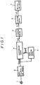
- Fig. 1 showing one embodiment to which the method according to the invention is applied.
- the output signal from a detector 1 is successively collected by data collecting means 2 whose output signals are successively input into data storing means 3 and stored therein as being past value data which is to be output to processing means 4.
- the processing means 4 receives the output signal from the data collecting means 2 as the newest value (Snew) of the detector 1, receives an output signal from the data storing means 3 as a preceding time value (Sold) of the detector 1, the preceding time value being used as the past value obtained a predetermined period of time before, which is stored in and successively renewed by the data storing means 3, successively performs the calculation of the absolute value of a difference as shown in the following equation (1) at each data collection time, and outputs the result (A) into counter means 5.
- A
- Limiter means 6 receives an output signal (C) from the counter means 5 and compares the output signal with a preset value (Cset) (a set period of time, by which noise disappearance can be decided). When the output signal (C) of the counter means 5 exceeds the preset value (Cset), a trigger signal (T) is turned “ON”. When the output signal (C) of the counter means 5 is smaller than the preset value (Cset), the trigger signal (T) if turned “OFF”. When the trigger output signal (T) of the limitter means 6 is "ON", notifying means 7 notifies the operator of the result, i.e. an occurance of noise reduction (or disappearance) phenomenon by means of a CRT, a printer, an annunciator or the like.
- Cset a preset value
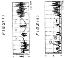
- Figs. 2(A) through 2(D) show examples of the output signals having various arrangements as shown in Fig. 1.
- Fig. 2(A) shows an example of the output signal (Snew) from the data collecting means 2, corresponding to the fluctuation with time of the output signal of the detector 1.
- 1 of Fig. 2(B) shows an example of the output signal (A) from the processing means 4, which is obtained by the absolute value of the difference between the newest value from the data collecting means 2 and the proceeding time value from the data storing means 3 which is successively renewed, to the output signal of the detector 1 shown in Fig. 2(A), 2 of Fig. 2(B) an example of a preset value (Aset) of the counter means 5.
- 1 of Fig. 2(C) shows an example of the output signal (C) of the counter means 5, when the input signal of the counter means 5 which is output signal 1 of Fig.
- Fig. 2(B) becomes smaller than the preset value
- 2 of Fig. 2(C) an example of the threshold value (Cset) of the limiter means 6
- Fig. 2(D) an example of the trigger output signal (T) of the limiter menns 6, when the counter number as shown in Fig. 2(C) exceeds the threshold value.
- the absolute value of a difference (A) between the present time value and the preceding time value, which are the output signals from the processing means 4 is larger than the preset value (Aset), whereby the output (C) from the counter means 5 is small and does not exceed the preset value (Cset).
- the absolute value of the difference (A) between the newest time value and the preceding time value, which are the output signals from the processing means 4 becomes sufficiently smaller than the preset value (Aset), whereby the output (C) from the counter means 5 increases and exceeds the threshold value (Cset).
- the trigger signal (T) is output into the notifying means 7 by the limiter means 6, to thereby notify the operator of the occurance of noise disappearance phenomena.
- the trigger signal (T) is turned off and the alarm is released.
- the absolute value of the difference between the preceding time value and the newest time value of the detected values is calculated by the processing means 4 and it is decided whether the absolute value of the difference is larger than the preset value or not, so that, even if only noise component of the detected value signal having a tendency of increasing or decreasing in the regions ⁇ , ⁇ and ⁇ shown in Fig. 2(A) is descreased, the detection of it can be made in high accuracy.
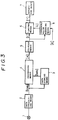
- this embodiment features in that there is additionally provided threshold value renewing means 8 which receives the output from the counter means 5 and a threshold value renewal request signal (R), and outputs a threshold renewed value (u) to the limiter means 6.
- the threshold value of the limiter means 6 is determined based on the threshold value renewal request signal (R) to the threshold value renewing means 8 such that the integrated value of the counter means 5 is statistically observed over a relatively long period of time and the threshold value is determined on the basis of the maximum value, so that such a meritorious effect can be added that a noise reduction detecting device having higher reliability is obtained.
- a reset signal is output from the processing means 4 to the data storing means 3, a detected value from the data collecting means 2, which is given to the data storing means 3 when this reset signal is received, is stored and renewed as a past value, and output to the processing means 4.
- the normal range can be empirically determined by taking in data in association with the characteristics of the respective detectors and the changes in the operating conditions, etc. Further, on the basis of the interrelations between the magnitudes of fluctuations of the detection signals and the threshold values of the count numbers, it becomes possible to examine what kind of result follows when one of the parameters is determined, and thereafter, the other is changed. Since this method of detecting a noise reduction and the detecting device therefor adopt a simple logic, the logic can be included in a computer assembled in the plant, monitoring of the noise reduction of the detection values in a large quantity can be performed without requiring so much load of the computer, and a period of time for observing detection values necessary for determining the noise disappearance can be automatically determined.
Landscapes
- Physics & Mathematics (AREA)
- General Physics & Mathematics (AREA)
- Engineering & Computer Science (AREA)
- Automation & Control Theory (AREA)
- Measurement Of Mechanical Vibrations Or Ultrasonic Waves (AREA)
Claims (4)
- Procédé pour détecter une réduction substantielle d'une composante de bruit dans des signaux émis par un détecteur, comprenant les étapes suivantes :
recueillir successivement les signaux émis par le détecteur dans un collecteur de données,
stocker les signaux recueillis dans une mémoire,
détecter la valeur absolue de la différence entre le signal couramment émis par le collecteur de données et l'un des signaux stockés, qui a été émis une période de temps prédéterminée auparavant,
comparer cette valeur absolue à une valeur préalablement fixée et incrémenter un nombre de comptes lorsque cette différence absolue est plus petite que ladite valeur préalablement fixée, mais effacer le nombre de comptes lorsque cette valeur absolue est supérieure à la valeur préalablement fixée, et
émettre une alarme lorsque le nombre de comptes est supérieur à une valeur de seuil préalablement fixée pour indiquer la réduction substantielle de la composante de bruit dans le signal émis par le détecteur. - Procédé selon la revendication 1, dans lequel la valeur de seuil est changée pour être une valeur maximale du nombre de comptes survenant pendant une période de temps prédéterminée après réception d'un signal de demande de renouvellement de la valeur de seuil.
- Dispositif de détection pour détecter une réduction notable d'une composante de bruit dans des signaux émis par un détecteur, comprenant :
des moyens de collecte des données (2) pour recueillir successivement lesdits signaux du détecteur (1),
des moyens de stockage des données (3) pour stocker les signaux de sortie émis par les moyens de collecte de données (2),
des moyens de traitement (4) pour traiter et émettre la valeur absolue de la différence entre le signal de sortie (Sn) sortant couramment des moyens de collecte des données (2) et l'un (Sp) des signaux de sortie stockés dans les moyens de stockage des données (3), qui a été émis une période de temps prédéterminée auparavant,
des moyens de compteur (5) pour y incrémenter un nombre de comptes lorsque la valeur absolue est inférieure à une valeur préalablement fixée, mais pour effacer ce nombre de comptes lorsque cette valeur absolue est supérieure à la valeur préalablement fixée,
des moyens limiteurs (6) sensibles au nombre de comptes pour émettre un signal de déclenchement lorsque ce nombre de comptes est supérieur à une valeur de seuil préalablement fixée, et
des moyens de notification (7) pour émettre une alarme en réponse à ce signal de déclenchement. - Dispositif de détection selon la revendication 3, comprenant en outre des moyens de renouvellement des valeurs de seuil (8) sensibles à un signal de demande de renouvellement de la valeur de seuil pour changer la valeur de seuil pour une valeur maximale du nombre de comptes survenant pendant une période de temps prédéterminée après réception de ce signal de demande de renouvellement de la valeur de seuil.
Applications Claiming Priority (4)
| Application Number | Priority Date | Filing Date | Title |
|---|---|---|---|
| JP26505/88 | 1988-02-09 | ||
| JP2650588 | 1988-02-09 | ||
| JP46224/88U | 1988-04-07 | ||
| JP4622488 | 1988-04-07 |
Publications (3)
| Publication Number | Publication Date |
|---|---|
| EP0328066A2 EP0328066A2 (fr) | 1989-08-16 |
| EP0328066A3 EP0328066A3 (en) | 1990-05-02 |
| EP0328066B1 true EP0328066B1 (fr) | 1994-12-07 |
Family
ID=26364291
Family Applications (1)
| Application Number | Title | Priority Date | Filing Date |
|---|---|---|---|
| EP89102145A Expired - Lifetime EP0328066B1 (fr) | 1988-02-09 | 1989-02-08 | Procédé de détection de la disparition de bruit et dispositif de détection |
Country Status (4)
| Country | Link |
|---|---|
| US (1) | US5016186A (fr) |
| EP (1) | EP0328066B1 (fr) |
| CA (1) | CA1318951C (fr) |
| DE (1) | DE68919720T2 (fr) |
Families Citing this family (4)
| Publication number | Priority date | Publication date | Assignee | Title |
|---|---|---|---|---|
| JP3324805B2 (ja) * | 1992-12-04 | 2002-09-17 | 住友化学工業株式会社 | 配管用閉塞検知装置 |
| US5394341A (en) * | 1993-03-25 | 1995-02-28 | Ford Motor Company | Apparatus for detecting the failure of a sensor |
| WO2004013715A1 (fr) * | 2002-08-01 | 2004-02-12 | Applied Materials, Inc. | Procede, systeme et support de manipulation de donnees de metrologie a mauvaise representation dans un systeme de commande de procede d'avant-garde |
| WO2013124903A1 (fr) * | 2012-02-24 | 2013-08-29 | 旭化成エレクトロニクス株式会社 | Dispositif de type capteur à fonction d'échantillonnage et système de traitement de données de capteur l'utilisant |
Family Cites Families (15)
| Publication number | Priority date | Publication date | Assignee | Title |
|---|---|---|---|---|
| JPS55138616A (en) * | 1979-04-16 | 1980-10-29 | Kansai Electric Power Co Inc:The | Bearing fault discriminating device |
| US4408294A (en) * | 1981-03-27 | 1983-10-04 | General Electric Company | Method for on-line detection of incipient cracks in turbine-generator rotors |
| US4587620A (en) * | 1981-05-09 | 1986-05-06 | Nippon Gakki Seizo Kabushiki Kaisha | Noise elimination device |
| US4462081A (en) * | 1982-04-05 | 1984-07-24 | System Development Corporation | Signal processing system |
| US4514797A (en) * | 1982-09-03 | 1985-04-30 | Gte Valeron Corporation | Worn tool detector utilizing normalized vibration signals |
| JPS5963344A (ja) * | 1982-10-01 | 1984-04-11 | Fuji Heavy Ind Ltd | 内燃機関の自己診断方式 |
| US4617630A (en) * | 1982-12-28 | 1986-10-14 | United Technologies Corporation | System fault discriminating electrostatic engine diagnostics |
| US4562548A (en) * | 1983-05-12 | 1985-12-31 | At&T Bell Laboratories | Alarm limit recentering arrangement for maintaining uniform alarm limit tolerances about a sloping regulation characteristic |
| JPH0619666B2 (ja) * | 1983-06-30 | 1994-03-16 | 富士通株式会社 | 故障診断処理方式 |
| US4635217A (en) * | 1984-10-09 | 1987-01-06 | Gte Government Systems Corporation | Noise threshold estimator for multichannel signal processing |
| EP0182742B1 (fr) * | 1984-11-15 | 1989-08-02 | Ascom Autophon Ag | Circuit de production d'un critère de réception |
| GB8500595D0 (en) * | 1985-01-10 | 1985-02-13 | Brownell Ltd | Leak rate detector circuit |
| US4751657A (en) * | 1985-07-08 | 1988-06-14 | General Electric Company | Method and apparatus for detecting axial cracks in rotors for rotating machinery |
| US4684989A (en) * | 1986-02-07 | 1987-08-04 | Rca Corporation | Signal background noise detector |
| US4718028A (en) * | 1986-02-18 | 1988-01-05 | Hughes Aircraft Company | Extremely high speed, real-time background filter for radiation detectors |
-
1989
- 1989-02-07 US US07/307,872 patent/US5016186A/en not_active Expired - Fee Related
- 1989-02-08 DE DE68919720T patent/DE68919720T2/de not_active Expired - Fee Related
- 1989-02-08 EP EP89102145A patent/EP0328066B1/fr not_active Expired - Lifetime
- 1989-02-08 CA CA000590417A patent/CA1318951C/fr not_active Expired - Fee Related
Also Published As
| Publication number | Publication date |
|---|---|
| CA1318951C (fr) | 1993-06-08 |
| DE68919720D1 (de) | 1995-01-19 |
| DE68919720T2 (de) | 1995-04-20 |
| EP0328066A2 (fr) | 1989-08-16 |
| EP0328066A3 (en) | 1990-05-02 |
| US5016186A (en) | 1991-05-14 |
Similar Documents
| Publication | Publication Date | Title |
|---|---|---|
| US5388445A (en) | Method for determining arrival and amplitude of a wave front and apparatus therefor | |
| KR100755955B1 (ko) | 수배전 설비 고장 진단 시스템 | |
| US5680109A (en) | Impulse line blockage detector systems and methods | |
| KR970000636B1 (ko) | 베어링의 이상검출장치 | |
| JP2560978B2 (ja) | パイプラインの監視方法及びその監視装置 | |
| EP0951663B1 (fr) | Systeme de commande faisant appel a la detection de defaillances | |
| EP0351833B1 (fr) | Système de diagnostic de défauts pour usines | |
| KR100719138B1 (ko) | 수배전 설비 고장 진단 방법 | |
| US20050231350A1 (en) | Method and system for generating automatic alarms based on trends detected in machine operation | |
| JPH0658425B2 (ja) | 原子力発電所の液体流通系の監視方法 | |
| US6453279B1 (en) | Statistical trend generator for predictive instrument maintenance | |
| EP0328066B1 (fr) | Procédé de détection de la disparition de bruit et dispositif de détection | |
| US7249287B2 (en) | Methods and apparatus for providing alarm notification | |
| GB2291502A (en) | Detection of breaking glass | |
| JPH08220278A (ja) | プラント監視装置及び監視方法 | |
| EP0019398A1 (fr) | Dispositif de surveillance de machines rotatives | |
| US5172099A (en) | Self monitoring fire detection system | |
| JPH0468275A (ja) | ターボ冷凍機のサージ検出装置 | |
| JP2885109B2 (ja) | 警報情報収集方式 | |
| JPH08122142A (ja) | 判別装置及び判別方法 | |
| JPH0228514A (ja) | ノイズ消失検知方法およびその装置 | |
| JP3952242B2 (ja) | 原子炉内構造物監視装置 | |
| JPH08328651A (ja) | データ収集方法及び装置 | |
| JPH0658298B2 (ja) | 軸受の異常診断装置 | |
| JPH05322714A (ja) | キャビテーション現象検出装置 |
Legal Events
| Date | Code | Title | Description |
|---|---|---|---|
| PUAI | Public reference made under article 153(3) epc to a published international application that has entered the european phase |
Free format text: ORIGINAL CODE: 0009012 |
|
| AK | Designated contracting states |
Kind code of ref document: A2 Designated state(s): CH DE ES FR GB IT LI |
|
| PUAL | Search report despatched |
Free format text: ORIGINAL CODE: 0009013 |
|
| AK | Designated contracting states |
Kind code of ref document: A3 Designated state(s): CH DE ES FR GB IT LI |
|
| 17P | Request for examination filed |
Effective date: 19900830 |
|
| 17Q | First examination report despatched |
Effective date: 19930402 |
|
| GRAA | (expected) grant |
Free format text: ORIGINAL CODE: 0009210 |
|
| AK | Designated contracting states |
Kind code of ref document: B1 Designated state(s): CH DE ES FR GB IT LI |
|
| PG25 | Lapsed in a contracting state [announced via postgrant information from national office to epo] |
Ref country code: IT Free format text: LAPSE BECAUSE OF FAILURE TO SUBMIT A TRANSLATION OF THE DESCRIPTION OR TO PAY THE FEE WITHIN THE PRE;WARNING: LAPSES OF ITALIAN PATENTS WITH EFFECTIVE DATE BEFORE 2007 MAY HAVE OCCURRED AT ANY TIME BEFORE 2007. THE CORRECT EFFECTIVE DATE MAY BE DIFFERENT FROM THE ONE RECORDED.SCRIBED TIME-LIMIT Effective date: 19941207 Ref country code: LI Effective date: 19941207 Ref country code: CH Effective date: 19941207 Ref country code: ES Free format text: THE PATENT HAS BEEN ANNULLED BY A DECISION OF A NATIONAL AUTHORITY Effective date: 19941207 |
|
| ET | Fr: translation filed | ||
| REF | Corresponds to: |
Ref document number: 68919720 Country of ref document: DE Date of ref document: 19950119 |
|
| REG | Reference to a national code |
Ref country code: CH Ref legal event code: PL |
|
| PLBE | No opposition filed within time limit |
Free format text: ORIGINAL CODE: 0009261 |
|
| STAA | Information on the status of an ep patent application or granted ep patent |
Free format text: STATUS: NO OPPOSITION FILED WITHIN TIME LIMIT |
|
| 26N | No opposition filed | ||
| PGFP | Annual fee paid to national office [announced via postgrant information from national office to epo] |
Ref country code: GB Payment date: 19970121 Year of fee payment: 9 |
|
| PGFP | Annual fee paid to national office [announced via postgrant information from national office to epo] |
Ref country code: FR Payment date: 19970214 Year of fee payment: 9 |
|
| PGFP | Annual fee paid to national office [announced via postgrant information from national office to epo] |
Ref country code: DE Payment date: 19970326 Year of fee payment: 9 |
|
| PG25 | Lapsed in a contracting state [announced via postgrant information from national office to epo] |
Ref country code: GB Free format text: LAPSE BECAUSE OF NON-PAYMENT OF DUE FEES Effective date: 19980208 |
|
| PG25 | Lapsed in a contracting state [announced via postgrant information from national office to epo] |
Ref country code: FR Free format text: THE PATENT HAS BEEN ANNULLED BY A DECISION OF A NATIONAL AUTHORITY Effective date: 19980228 |
|
| GBPC | Gb: european patent ceased through non-payment of renewal fee |
Effective date: 19980208 |
|
| PG25 | Lapsed in a contracting state [announced via postgrant information from national office to epo] |
Ref country code: DE Free format text: LAPSE BECAUSE OF NON-PAYMENT OF DUE FEES Effective date: 19981103 |
|
| REG | Reference to a national code |
Ref country code: FR Ref legal event code: ST |