EP0328034A2 - Rectifieuse d'outillage - Google Patents
Rectifieuse d'outillage Download PDFInfo
- Publication number
- EP0328034A2 EP0328034A2 EP19890102053 EP89102053A EP0328034A2 EP 0328034 A2 EP0328034 A2 EP 0328034A2 EP 19890102053 EP19890102053 EP 19890102053 EP 89102053 A EP89102053 A EP 89102053A EP 0328034 A2 EP0328034 A2 EP 0328034A2
- Authority
- EP
- European Patent Office
- Prior art keywords
- grinding
- axis
- machine
- tool
- machine according
- Prior art date
- Legal status (The legal status is an assumption and is not a legal conclusion. Google has not performed a legal analysis and makes no representation as to the accuracy of the status listed.)
- Withdrawn
Links
- 238000003754 machining Methods 0.000 claims abstract description 3
- 230000005540 biological transmission Effects 0.000 description 2
- 238000011161 development Methods 0.000 description 1
- 230000018109 developmental process Effects 0.000 description 1
- 238000004519 manufacturing process Methods 0.000 description 1
Images

Classifications
-
- B—PERFORMING OPERATIONS; TRANSPORTING
- B24—GRINDING; POLISHING
- B24B—MACHINES, DEVICES, OR PROCESSES FOR GRINDING OR POLISHING; DRESSING OR CONDITIONING OF ABRADING SURFACES; FEEDING OF GRINDING, POLISHING, OR LAPPING AGENTS
- B24B41/00—Component parts such as frames, beds, carriages, headstocks
- B24B41/02—Frames; Beds; Carriages
Definitions
- the invention relates to a tool grinding machine with a machine frame, a table which can be moved horizontally along the x-axis on the frame, a first dividing device with a chuck for clamping a workpiece, a horizontally along the y-axis and vertically along the z-axis movable grinding head, and a grinding spindle which can be driven and protrudes from the grinding head and to which a grinding wheel can be attached for machining a clamped workpiece.
- the grinding head is seated on a cylindrical column of height, which is slidably mounted in a corresponding cylindrical bearing bush and can be moved vertically along the z-axis.
- the diameter of the height column and the corresponding bearing bush must be as large as possible.
- the distance between the vertical column and the work table or the workpiece must not be too large in order not to impair the precision of the tool production.
- the large diameter of the height column and the small distance of the height column from the workpiece considerably restrict the free space on the workpiece, as a result of which the possibilities of movement of the grinding head and thus the possible uses of the grinding machine are limited.
- the object of the invention is therefore to provide a tool grinding machine of the type mentioned in the introduction to further develop that a slight play in the vertical movement of the grinding head, a sufficiently rigid attachment of the grinding head and a sufficiently large free space on the workpiece are realized.
- This task is characterized according to the invention in the tool grinding machine of the type mentioned at the outset by a vertical machine stand which can be moved along the y axis, and a support which can be moved vertically on the machine stand and to which the grinding head is about an axis lying in a vertical plane (C axis ) is rotatably mounted.
- a vertical machine stand which carries vertical guides in which a support carrying the grinding head can be moved vertically. Since the machine stand - like the well-known height column - can also be moved along the y-axis, and since the grinding head on the support is rotatably supported about an axis lying in a vertical plane, the grinding machine according to the invention, which is available in known grinding machines, Axis path control also implemented (x-axis horizontally in the direction of the table, y-axis horizontally perpendicular to the table, z-axis vertical movement, A-axis: rotation of the workpiece around the axis of the first sub-apparatus, C-axis: rotation around a vertical axis) .
- the vertical guide for the support is particularly preferably arranged on the outer surface of the machine stand facing the table.
- the support preferably contains a base part which can be moved in this guide and a table which is rotatably mounted on the base part about a horizontal axis (B axis) and on which the grinding head is arranged, preferably by means of a second part apparatus fastened to a vertical outer surface of the turntable.
- the grinding head is preferably rotatably mounted in the bearing of the second sub-apparatus, which normally receives the chuck of the sub-apparatus.
- This embodiment of the invention has the essential advantage that a unit known per se, namely a dividing device, can be used to hold the grinding head, and that, in particular, by splitting the support into a base part and a rotary table, an additional rotary movement about the B axis, therefore allows a 6-axis path control. It is therefore also possible to grind complicated tools with the grinding machine according to the invention, which were previously lacking in clearance and ins particular were not feasible due to the lack of sufficient mobility of the grinding head.
- the grinding machine according to the invention is provided with a hydraulic system which is designed such that the rotary table is sucked hydraulically against the base part of the support in the grinding operation, that is to say it is hydraulically clamped.
- the grinding head for the grinding operation can be clamped hydraulically against the second dividing head. In this way, a particularly rigid, almost backlash-free connection between the grinding head and the machine stand is established as soon as the grinding operation begins.
- the machine stand can preferably be moved in a horizontal guide which is attached to the machine frame.
- Appropriately spaced guide rails with ground-in ball grooves, in which the corresponding ball bearings fastened to the machine stand or to the support run, are preferably used as a guide for the machine stand and as a vertical guide for the support.
- the first sub-apparatus in the grinding machine according to the invention is advantageously seen by the user on the table to the right of the workpiece, and the associated tailstock to the left of the workpiece or grinding head. Since the tools to be produced usually all have a chip space with a right-hand twist, the cutting edges of these tools are then - seen from the user of the machine - in front of the grinding wheel of the grinding machine, ie they are visible to the user, so that the user can control the grinding wheel and the Can keep oil release etc. visually under control.
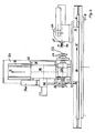
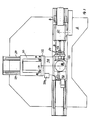
- the tool grinding machine shown in FIGS. 1 to 3 has a machine frame 2, on which two parallel guide rails 8 are fastened along an x-axis with ground ball grooves.
- a table 4 has on its underside at a corresponding distance from each other ball bearings 6 which run in the grooves of the guide rails 8, so that the table 4 can be moved along the x-axis on the horizontal working surface of the machine frame 2.
- a first sub-apparatus 60 is fastened on the table 4 and carries a chuck 61 for receiving a workpiece 70 to be machined. If necessary, a tailstock can be clamped onto the table 4 at a predetermined distance from the first sub-apparatus 60 in order to support the free end of the workpiece 70.
- two guide rails 24 are fastened, which also have ground ball grooves.
- a vertical machine stand 20 is fastened on a base plate 22. Below the base plate 22, ball bearings 23 are arranged at a predetermined distance from one another, which run in the ball grooves of the guide rails 24.
- the machine stand 20 can be moved horizontally along a y-axis by means of the guide formed from ball bearings 23 and guide rails 24.
- the support 30 consists of a base part 32, to which a plurality of ball bearings 33 are fastened at a predetermined distance from one another and run in the ball grooves of the guide rails 34.
- a rotary table 36 is arranged on the base part 32 and is rotatably mounted on the base part 32 about a horizontal axis, the so-called B axis, and can be rotated by means of a drive motor 36a.
- the support also includes a second dividing head 38, which is on a vertical outer surface 37 of the turntable 36 is increasing.
- a grinding head 50 is rotatably mounted about an axis lying in a vertical plane, the so-called C-axis.
- a drivable grinding spindle 52 is mounted in the grinding head, transverse to the C axis, which receives one or more grinding wheels 54 at a free end protruding from the grinding head, by means of which the workpiece 70 is machined.
- a drive motor 42 is attached above the grinding head 50 at a predetermined distance and with a shaft running parallel to the grinding head 50, which drives the grinding spindle 52 via suitable transmission elements, for example a belt drive.
- the grinding machine contains a hydraulic system (not shown), which serves to move the various structural units, such as the machine stand, support, table and / or rotary table and grinding head.
- a hydraulic system (not shown), which serves to move the various structural units, such as the machine stand, support, table and / or rotary table and grinding head.
- electric drive motors for driving these machine units are possible, in which case the rotary movement of the drive motors can then be converted into the required translational movements by means of spindle drives.
Landscapes
- Engineering & Computer Science (AREA)
- Mechanical Engineering (AREA)
- Constituent Portions Of Griding Lathes, Driving, Sensing And Control (AREA)
- Grinding Of Cylindrical And Plane Surfaces (AREA)
Applications Claiming Priority (2)
| Application Number | Priority Date | Filing Date | Title |
|---|---|---|---|
| DE3804010 | 1988-02-10 | ||
| DE19883804010 DE3804010A1 (de) | 1988-02-10 | 1988-02-10 | Werkzeug-schleifmaschine |
Publications (2)
| Publication Number | Publication Date |
|---|---|
| EP0328034A2 true EP0328034A2 (fr) | 1989-08-16 |
| EP0328034A3 EP0328034A3 (fr) | 1991-05-02 |
Family
ID=6347045
Family Applications (1)
| Application Number | Title | Priority Date | Filing Date |
|---|---|---|---|
| EP19890102053 Withdrawn EP0328034A3 (fr) | 1988-02-10 | 1989-02-07 | Rectifieuse d'outillage |
Country Status (3)
| Country | Link |
|---|---|
| EP (1) | EP0328034A3 (fr) |
| JP (1) | JPH01316157A (fr) |
| DE (1) | DE3804010A1 (fr) |
Cited By (7)
| Publication number | Priority date | Publication date | Assignee | Title |
|---|---|---|---|---|
| EP0424815A1 (fr) * | 1989-10-23 | 1991-05-02 | Z. BAVELLONI S.p.A. | Machine de gravure automatique, en particulier pour graver les faces de pièces plates en général et des plaques de verre en particulier |
| WO1995004629A1 (fr) * | 1993-08-07 | 1995-02-16 | Strausak Ag Maschinenfabrik | Station universelle de meulage |
| CN104044077A (zh) * | 2013-03-15 | 2014-09-17 | 昆山齐升磨料磨具有限公司 | 一种新型的平面磨床 |
| CN105479287A (zh) * | 2016-01-15 | 2016-04-13 | 商丘金振源电子科技有限公司 | 三轴去毛刺系统 |
| CN107414188A (zh) * | 2017-09-22 | 2017-12-01 | 苏州欣航微电子有限公司 | 一种用于机械加工的机用铰刀旋转装置 |
| CN108705415A (zh) * | 2018-07-03 | 2018-10-26 | 杨真 | 一种卧式汽车配件加工用打磨装置 |
| US10421172B2 (en) * | 2015-12-01 | 2019-09-24 | Tokyo Seimitsu Co. Ltd. | Processing device |
Families Citing this family (4)
| Publication number | Priority date | Publication date | Assignee | Title |
|---|---|---|---|---|
| CN100537140C (zh) * | 2008-03-28 | 2009-09-09 | 重庆三磨海达磨床有限公司 | 一种适用于自由曲面的磨削装置 |
| CN103753364A (zh) * | 2014-01-14 | 2014-04-30 | 苏州苏铸重工有限公司 | 数控磨削机床 |
| CN105458862A (zh) * | 2015-12-16 | 2016-04-06 | 江苏森莱浦光电科技有限公司 | 一种uhp球泡打磨机 |
| CN106141822A (zh) * | 2016-08-26 | 2016-11-23 | 马鞍山俊强精密机械设备有限公司 | 一种圆盘刀数控研磨机及其磨削方法 |
Family Cites Families (5)
| Publication number | Priority date | Publication date | Assignee | Title |
|---|---|---|---|---|
| FR1355181A (fr) * | 1962-04-16 | 1964-03-13 | Hammond Machinery Builders Inc | Procédé de polissage et machine à polir pour sa mise en oeuvre |
| SE316706B (fr) * | 1964-04-06 | 1969-10-27 | Ulvsunda Verkstaeder Ab | |
| US4186529A (en) * | 1977-06-28 | 1980-02-05 | S. E. Huffman Corporation | Programmably controlled method for grinding end cutting tools and the like |
| FR2462232A1 (fr) * | 1979-08-02 | 1981-02-13 | Treuillet Bernard | Perfectionnements aux machines pour l'affutage des outils d'usinage |
| DE3538795A1 (de) * | 1985-10-31 | 1987-05-07 | Volker Zang | Schleifkopf fuer eine werkzeugschleifmaschine fuer wendelgenutete schneidwerkzeuge |
-
1988
- 1988-02-10 DE DE19883804010 patent/DE3804010A1/de not_active Withdrawn
-
1989
- 1989-02-07 EP EP19890102053 patent/EP0328034A3/fr not_active Withdrawn
- 1989-02-10 JP JP3253989A patent/JPH01316157A/ja active Pending
Cited By (8)
| Publication number | Priority date | Publication date | Assignee | Title |
|---|---|---|---|---|
| EP0424815A1 (fr) * | 1989-10-23 | 1991-05-02 | Z. BAVELLONI S.p.A. | Machine de gravure automatique, en particulier pour graver les faces de pièces plates en général et des plaques de verre en particulier |
| WO1995004629A1 (fr) * | 1993-08-07 | 1995-02-16 | Strausak Ag Maschinenfabrik | Station universelle de meulage |
| CN104044077A (zh) * | 2013-03-15 | 2014-09-17 | 昆山齐升磨料磨具有限公司 | 一种新型的平面磨床 |
| US10421172B2 (en) * | 2015-12-01 | 2019-09-24 | Tokyo Seimitsu Co. Ltd. | Processing device |
| CN105479287A (zh) * | 2016-01-15 | 2016-04-13 | 商丘金振源电子科技有限公司 | 三轴去毛刺系统 |
| CN107414188A (zh) * | 2017-09-22 | 2017-12-01 | 苏州欣航微电子有限公司 | 一种用于机械加工的机用铰刀旋转装置 |
| CN107414188B (zh) * | 2017-09-22 | 2019-02-22 | 广东泓睿科技有限公司 | 一种用于机械加工的机用铰刀旋转装置 |
| CN108705415A (zh) * | 2018-07-03 | 2018-10-26 | 杨真 | 一种卧式汽车配件加工用打磨装置 |
Also Published As
| Publication number | Publication date |
|---|---|
| JPH01316157A (ja) | 1989-12-21 |
| DE3804010A1 (de) | 1989-08-24 |
| EP0328034A3 (fr) | 1991-05-02 |
Similar Documents
| Publication | Publication Date | Title |
|---|---|---|
| EP1338376B1 (fr) | Fraiseuse pour fraisage et tournage de pièces en forme de barre | |
| DE3005606C2 (de) | Numerisch gesteuerte Maschine zum Schleifen mehrerer unterschiedlicher Flächen an ein- und demselben Werkstück | |
| DE3502328C2 (fr) | ||
| DE3511614A1 (de) | Werkzeugmaschine zur mehrfachen flaechenbearbeitung | |
| WO2001083159A1 (fr) | Dispositif de pre-usinage et/ou de finition d'usinage mecanique de pieces moulees en fonte | |
| DE4444614A1 (de) | Werkzeugmaschine | |
| DE3917913A1 (de) | Drahterodiereinrichtung | |
| DE3315948C2 (fr) | ||
| EP1525065B1 (fr) | Machine-outil dotee de deux broches porte-pieces | |
| DE69114514T2 (de) | Schneid- und schleifvorrichtung für einen glasscheibenrand. | |
| EP0328034A2 (fr) | Rectifieuse d'outillage | |
| DE3904686C1 (en) | CNC-machine for grinding workpieces with curved surfaces, in particular turbine blades, and also for grinding and polishing decorative grooves on hollow glassware or similar workpieces | |
| DE69126135T2 (de) | Portalwerkzeugmaschine | |
| DE880836C (de) | Vorrichtung zur Bearbeitung langgestreckter ebener oder leicht balliger, beliebig geneigter Flaechen | |
| EP4058237A1 (fr) | Machine à meuler circulaire dotée d'une unité de dressage | |
| DE202004016057U1 (de) | Miniatur-Bearbeitungszentrum mit vielachsigem Bohr- und Fräswerkzeug | |
| DE3707230C2 (fr) | ||
| AT398051B (de) | Laufdraht-schneidmaschine | |
| DE2620477C2 (de) | Gleitschleif- oder -poliermaschine | |
| DE2217352A1 (de) | Werkstueckaufspanntisch | |
| DE3401086C2 (fr) | ||
| DE4211738C2 (de) | Vorrichtung zum stationären Betrieb motorgetriebener spanabhebender Handarbeitsgeräte | |
| DE8801687U1 (de) | Werkzeug-Schleifmaschine | |
| EP0316742A2 (fr) | Machine pour la finition de pièces | |
| DE3930071A1 (de) | Werkzeugmaschine |
Legal Events
| Date | Code | Title | Description |
|---|---|---|---|
| PUAI | Public reference made under article 153(3) epc to a published international application that has entered the european phase |
Free format text: ORIGINAL CODE: 0009012 |
|
| AK | Designated contracting states |
Kind code of ref document: A2 Designated state(s): AT BE CH DE ES FR GB GR IT LI LU NL SE |
|
| RAP1 | Party data changed (applicant data changed or rights of an application transferred) |
Owner name: BREMER VULKAN AG SCHIFFBAU UND MASCHINENFABRIK |
|
| RIN1 | Information on inventor provided before grant (corrected) |
Inventor name: BUESSENSCHUETT, HEINZ |
|
| PUAL | Search report despatched |
Free format text: ORIGINAL CODE: 0009013 |
|
| AK | Designated contracting states |
Kind code of ref document: A3 Designated state(s): AT BE CH DE ES FR GB GR IT LI LU NL SE |
|
| RAP1 | Party data changed (applicant data changed or rights of an application transferred) |
Owner name: H. WOHLENBERG KG GMBH & CO. |
|
| 17P | Request for examination filed |
Effective date: 19911031 |
|
| RAP1 | Party data changed (applicant data changed or rights of an application transferred) |
Owner name: GUEHRING AUTOMATION GMBH |
|
| 17Q | First examination report despatched |
Effective date: 19920916 |
|
| STAA | Information on the status of an ep patent application or granted ep patent |
Free format text: STATUS: THE APPLICATION HAS BEEN WITHDRAWN |
|
| 18W | Application withdrawn |
Withdrawal date: 19930123 |