EP0327277A1 - Un assemblage de siège - Google Patents
Un assemblage de siège Download PDFInfo
- Publication number
- EP0327277A1 EP0327277A1 EP89300847A EP89300847A EP0327277A1 EP 0327277 A1 EP0327277 A1 EP 0327277A1 EP 89300847 A EP89300847 A EP 89300847A EP 89300847 A EP89300847 A EP 89300847A EP 0327277 A1 EP0327277 A1 EP 0327277A1
- Authority
- EP
- European Patent Office
- Prior art keywords
- cushion
- shell
- seat assembly
- framework
- assembly according
- Prior art date
- Legal status (The legal status is an assumption and is not a legal conclusion. Google has not performed a legal analysis and makes no representation as to the accuracy of the status listed.)
- Withdrawn
Links
Images


Classifications
-
- A—HUMAN NECESSITIES
- A47—FURNITURE; DOMESTIC ARTICLES OR APPLIANCES; COFFEE MILLS; SPICE MILLS; SUCTION CLEANERS IN GENERAL
- A47C—CHAIRS; SOFAS; BEDS
- A47C31/00—Details or accessories for chairs, beds, or the like, not provided for in other groups of this subclass, e.g. upholstery fasteners, mattress protectors, stretching devices for mattress nets
- A47C31/02—Upholstery attaching means
-
- A—HUMAN NECESSITIES
- A47—FURNITURE; DOMESTIC ARTICLES OR APPLIANCES; COFFEE MILLS; SPICE MILLS; SUCTION CLEANERS IN GENERAL
- A47C—CHAIRS; SOFAS; BEDS
- A47C3/00—Chairs characterised by structural features; Chairs or stools with rotatable or vertically-adjustable seats
- A47C3/12—Chairs characterised by structural features; Chairs or stools with rotatable or vertically-adjustable seats with shell-shape seat and back-rest unit, e.g. having arm rests
-
- A—HUMAN NECESSITIES
- A47—FURNITURE; DOMESTIC ARTICLES OR APPLIANCES; COFFEE MILLS; SPICE MILLS; SUCTION CLEANERS IN GENERAL
- A47C—CHAIRS; SOFAS; BEDS
- A47C7/00—Parts, details, or accessories of chairs or stools
- A47C7/02—Seat parts
- A47C7/18—Seat parts having foamed material included in cushioning part
- A47C7/185—Seat parts having foamed material included in cushioning part with a stiff, rigid support
-
- A—HUMAN NECESSITIES
- A47—FURNITURE; DOMESTIC ARTICLES OR APPLIANCES; COFFEE MILLS; SPICE MILLS; SUCTION CLEANERS IN GENERAL
- A47C—CHAIRS; SOFAS; BEDS
- A47C7/00—Parts, details, or accessories of chairs or stools
- A47C7/02—Seat parts
- A47C7/18—Seat parts having foamed material included in cushioning part
- A47C7/20—Seat parts having foamed material included in cushioning part with reinforcement in the foam layer
-
- Y—GENERAL TAGGING OF NEW TECHNOLOGICAL DEVELOPMENTS; GENERAL TAGGING OF CROSS-SECTIONAL TECHNOLOGIES SPANNING OVER SEVERAL SECTIONS OF THE IPC; TECHNICAL SUBJECTS COVERED BY FORMER USPC CROSS-REFERENCE ART COLLECTIONS [XRACs] AND DIGESTS
- Y10—TECHNICAL SUBJECTS COVERED BY FORMER USPC
- Y10S—TECHNICAL SUBJECTS COVERED BY FORMER USPC CROSS-REFERENCE ART COLLECTIONS [XRACs] AND DIGESTS
- Y10S160/00—Flexible or portable closure, partition, or panel
- Y10S160/15—Web-to-tube fasteners
-
- Y—GENERAL TAGGING OF NEW TECHNOLOGICAL DEVELOPMENTS; GENERAL TAGGING OF CROSS-SECTIONAL TECHNOLOGIES SPANNING OVER SEVERAL SECTIONS OF THE IPC; TECHNICAL SUBJECTS COVERED BY FORMER USPC CROSS-REFERENCE ART COLLECTIONS [XRACs] AND DIGESTS
- Y10—TECHNICAL SUBJECTS COVERED BY FORMER USPC
- Y10S—TECHNICAL SUBJECTS COVERED BY FORMER USPC CROSS-REFERENCE ART COLLECTIONS [XRACs] AND DIGESTS
- Y10S297/00—Chairs and seats
- Y10S297/01—Foam
-
- Y—GENERAL TAGGING OF NEW TECHNOLOGICAL DEVELOPMENTS; GENERAL TAGGING OF CROSS-SECTIONAL TECHNOLOGIES SPANNING OVER SEVERAL SECTIONS OF THE IPC; TECHNICAL SUBJECTS COVERED BY FORMER USPC CROSS-REFERENCE ART COLLECTIONS [XRACs] AND DIGESTS
- Y10—TECHNICAL SUBJECTS COVERED BY FORMER USPC
- Y10S—TECHNICAL SUBJECTS COVERED BY FORMER USPC CROSS-REFERENCE ART COLLECTIONS [XRACs] AND DIGESTS
- Y10S297/00—Chairs and seats
- Y10S297/02—Molded
Definitions
- the present invention relates to a novel seat assembly. More particularly, the invention is directed to a seat assembly that permits the fast and economical fabrication and assembly of an upholstered foam cushion to a rigid support shell. Such seat assemblies are commonly used in lawn and garden vehicles and in small recreational vehicles.
- the present invention overcomes the above described problems by providing a novel seat construction that permits simple and economical assembly. Moreover, the seat assembly has a clean and uncluttered appearance that is aesthetically appealing.
- a seat assembly having a cushion assembly, a rigid shell, a cover and means to attach the cushion assembly to the shell.
- the cushion assembly includes a foam cushion and an internal rigid framework molded integrally within the foam cushion.
- the cushion has a side portion with a lip having a predetermined configuration, and the shell has a matching edge which mates with the cushion lip when the seat is assembled.
- the rigid framework is located within the cushion in close proximity to the side portion.
- the rigid framework comprises a tubular member.
- These embodiments also include a variety of means to attach the shell to the tubular member and access passages in the cushion permitting that attachment.
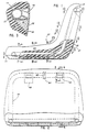
- a seat assembly designated generally as 20, is shown having a cushion assembly 22 and a shell 24.
- the cushion assembly comprises a foam cushion 26 and a rigid internal framework 28 that is integrally molded within the cushion.
- the foam cushion includes front and back portions, 30 and 32 respectively, and a side portion 34 having a lip 36.
- the lip 36 extends entirely around the perimeter of the cushion 26 along the sides of the seat and backrest. Thus, the lip has a predetermined dimension and shape for any given seat design.
- the shell 24 is constructed from metal, plastic or other rigid material and includes a peripheral edge 38 configured to align and mate with cushion lip 36 when the shell is attached to the back portion of cushion 26.
- the seat assembly of the present invention also includes a cover 40 comprising sheet vinyl, fabric or other conventional upholstery goods.
- the cover 40 overlies the front portion 30 of cushion 26 and is typically bonded to front portion 30 and part of the side portion 34 by any one of various techniques well known to those of skill in the art.
- the cover also includes a free peripheral section 42 that extends from the front portion of the cushion and between the lip 36 and shell edge 38. As a result, the free peripheral section 42 of the cover is mechanically secured between the shell 24 and cushion 26 when the seat assembly is completed.
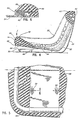
- the internal framework of the cushion assembly comprises a tubular member 44 which extends completely around the cushion 26 in close proximity to side portion 34 and lip 36.
- the purpose of the framework and tubular member 44 is to maintain the predetermined dimension and shape of the cushion lip 36 which would otherwise vary to an unacceptable degree because of the inherent dimensional variance in molded cushions of this size.
- This shrink factor can vary between 1 to 2 percent.
- the variance in shrink must be accommodated in any joint or interface between hard and soft goods. For example, on an 18 inch seat dimension the cushion shrink can vary from 0.18 to 0.36 inches.
- the shrinkage range will amount to only 0.01 to 0.02 inches. This small variance (0.01 inches) is within acceptable, predetermined manufacturing tolerances and is easily accounted for in the design of the seat. In other words, if properly positioned in proximity to the side of the cushion, the rigid internal framework will maintain the desired predetermined manufacturing tolerance. As a result, the interface between the cushion lip 36 and shell edge 38 is substantially uniform and aesthetically pleasing.
- the tubular member 44 is positioned as close to the lip 36 as is possible without causing voids to form during molding and without being noticeable to the user or occupant of the seat.
- the precise spacing will vary depending upon the formulation of the foam used in cushion 26 and the shape of the cushion and shell 24.
- FIGURE 7-13 show a typical placement of the tubular member relative to the cushion side portion 34 and lip 36. While the tubular member 44 is spaced from the outer surface of the cushion 26, i.e. it is encapsulated by foam, it is nevertheless sufficiently close to side portion 34 in order to maintain the shape and dimensions of lip 36. Of course, it is also desireable to position the tubular member 44 close to the back portion 32 and away from the front portion 30 of the cushion.
- the cushion assembly is pivotally or rotatably mounted to shell 24.
- the shell 24 includes means for fastening the cushion assembly framework to the shell, such as brackets 46 which extend through passages 48 in cushion 26 and which rotatably support the tubular member 44 by means of upwardly opening bearings 50.
- access passages 48 include an expanded rear opening 52 to facilitate insertion of brackets 46 and rotation of the cushion assembly to its final position where it nests within shell 24.
- Framework 28 may also include plate 56 which bridges the framework across the seat of cushion 26.
- Plate 56 also includes fastening means, such as threaded fasteners 58, which align with holes 60 in shell 24.
- fastening means such as threaded fasteners 58
- a force transmitting strut 62 which extends from the centerline of shell 24 to the tubular member 44 through passage 64. In this way, any force applied to the upper rear portion of the seat assembly will be transmitted directly to the framework and, via fasteners 58, to the vehicle frame. Also, temporary retaining elements 66 may be employed to engage plate 56 and hold the seat assembly in its assembled condition prior to installation into a vehicle.
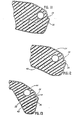
- Figures 14-17 depict alternative embodiments for various means to attach the shell 24 to the internal framework 28 including tubular member 44.
- Figure 14 illustrates an interior shoulder 72A of the shell 24 that mates with the member 44 and is secured by threaded fastener 74A.
- Recess 76A permits fastener 74A to remain flush with or below the surface of shell 24.
- Figure 15 similarly shows a threaded fastener 74B, shoulder 72B, and recess 76B.
- fastener 74A merely passes through the wall of member 44.
- a solid interior portion 45 of tubular member 44 allows more threads of the fastener to hold the tubular member 44.
- Edges 47 and 77 provide an additional interlocking feature of the attachment means of Figure 15.
- Figures 16 and 17 show two ways of clipping the shell 24 to the tubular member 44.
- shoulder 72C extends into the interior of member 44 by a pair of interior clips 75A.
- exterior clips 75B are secured around the outside of member 44.
- access passages 48 and rear openings 52 may be incorporated into the structures to facilitate the attachment of the framework 28 and the shell 24.
- the degree of rotation, if any, of the cushion assembly necessary to securely set the assembly into its final nested position in the shell will be determined by the particular embodiment and method of manufacture chosen.
- brackets or shoulders positioned on the shell can be easily indexed with the access passages molded in the cushion to facilitate proper location of the cushion and shell in the assembly operation.
Landscapes
- Seats For Vehicles (AREA)
Applications Claiming Priority (4)
| Application Number | Priority Date | Filing Date | Title |
|---|---|---|---|
| US152108 | 1988-02-04 | ||
| US07/152,108 US4792189A (en) | 1988-02-04 | 1988-02-04 | Seat assembly |
| US07/286,470 US4880276A (en) | 1988-02-04 | 1988-12-19 | Seat assembly |
| US286470 | 1988-12-19 |
Publications (1)
| Publication Number | Publication Date |
|---|---|
| EP0327277A1 true EP0327277A1 (fr) | 1989-08-09 |
Family
ID=22541538
Family Applications (1)
| Application Number | Title | Priority Date | Filing Date |
|---|---|---|---|
| EP89300847A Withdrawn EP0327277A1 (fr) | 1988-02-04 | 1989-01-27 | Un assemblage de siège |
Country Status (2)
| Country | Link |
|---|---|
| US (2) | US4792189A (fr) |
| EP (1) | EP0327277A1 (fr) |
Families Citing this family (28)
| Publication number | Priority date | Publication date | Assignee | Title |
|---|---|---|---|---|
| US5405178A (en) * | 1990-01-18 | 1995-04-11 | C.A. Greiner & Sohne Gesellschaft M.B.H. | Fire resistant vehicle seat |
| US5067772A (en) * | 1990-03-29 | 1991-11-26 | Michigan Seat Company | Foam seat with insert |
| US5067773A (en) * | 1990-09-04 | 1991-11-26 | Michigan Seat Company | Foam seat cushion with clamped edges |
| US5318346A (en) * | 1991-05-30 | 1994-06-07 | Steelcase Inc. | Chair with zero front rise control |
| FR2696917B1 (fr) * | 1992-10-16 | 1995-01-06 | Chairtech | Perfectionnement pour siège. |
| US5395161A (en) * | 1992-11-12 | 1995-03-07 | Prince Corporation | Armrest |
| US5630643A (en) * | 1993-06-01 | 1997-05-20 | Steelcase Inc | Upholstered chair with two-piece shell |
| US5489145A (en) * | 1994-01-13 | 1996-02-06 | Westinghouse Electric Corporation | Chair cusion and upholstery assembly and method |
| US5551749A (en) * | 1996-01-11 | 1996-09-03 | Reher; Judy M. | Child support cushion |
| US5671978A (en) * | 1996-06-28 | 1997-09-30 | Lear Corporation | Vehicle seat cushion |
| US5879055A (en) * | 1996-09-24 | 1999-03-09 | Lear Corporation | Automative seat back panel |
| US5826946A (en) * | 1997-10-30 | 1998-10-27 | Lear Corp. | Vehicle seat support panel |
| US6106071A (en) * | 1998-05-12 | 2000-08-22 | Johnson Controls Technology Company | Twin frame seat assembly |
| US6149240A (en) * | 1998-12-04 | 2000-11-21 | Pietrzak; Joseph J. | Shroud for the underside of a chair, and a molded seat frame for use therewith |
| US5997096A (en) * | 1999-03-05 | 1999-12-07 | Chen; Su-Ming | Chair with a seat-supporting unit capable of resisting left and right tilting of a seat supported thereon |
| US6425637B1 (en) * | 1999-04-19 | 2002-07-30 | Steelcase Development Corporation | Cushion construction for furniture |
| US6536844B2 (en) * | 1999-11-18 | 2003-03-25 | Moeller Marine Products | Blow-molded seat assembly and method of making same |
| US6523900B1 (en) | 2000-09-01 | 2003-02-25 | Irwin Seating Company | Chair seat |
| NL1021674C1 (nl) * | 2002-10-17 | 2004-04-20 | Edwin Johannus Niekel | Lichtgewicht zitmeubelconstructie met zgn. memory werking. |
| US7396078B2 (en) | 2004-02-05 | 2008-07-08 | Wenger Corporation | Music posture chair |
| US7510244B1 (en) | 2005-12-01 | 2009-03-31 | Shin Justin H | Event chair construction |
| US7427107B2 (en) * | 2006-08-10 | 2008-09-23 | Po Hsuan Yang | Movable backrest for a chair |
| US8128175B2 (en) | 2008-06-04 | 2012-03-06 | Herman Miller, Inc. | Suspension seating |
| US8991930B2 (en) * | 2008-09-22 | 2015-03-31 | Johnson Controls Technology Company | Closed cell foam vehicle interior component and method of making same |
| US20110018221A1 (en) * | 2009-07-27 | 2011-01-27 | Benjamin A Anooshian | Wheelchair having reversible seat rail support structure |
| US9580001B2 (en) | 2014-10-20 | 2017-02-28 | Toyota Motor Engineering & Manuufacturing North America, Inc. | Side shield trench on seat cushion |
| US10507922B2 (en) * | 2017-02-03 | 2019-12-17 | Jamco Corporation | Energy absorbing backshell |
| US11242118B1 (en) * | 2020-07-23 | 2022-02-08 | Wieland Designs, Inc. | Seat with reclining mechanism for marine vessel |
Citations (4)
| Publication number | Priority date | Publication date | Assignee | Title |
|---|---|---|---|---|
| GB895911A (en) * | 1957-08-27 | 1962-05-09 | Tan Sad Chair Co 1931 Ltd | An improved seat bottom |
| US3669499A (en) * | 1970-12-30 | 1972-06-13 | Steelcase Inc | Chair |
| FR2229368A1 (fr) * | 1973-05-16 | 1974-12-13 | Turcksin C | |
| FR2447166A1 (fr) * | 1979-01-23 | 1980-08-22 | Vogel Ignaz Fahrzeugsitze | Siege pour passager de vehicule de transport en commun |
Family Cites Families (22)
| Publication number | Priority date | Publication date | Assignee | Title |
|---|---|---|---|---|
| US2979119A (en) * | 1958-09-29 | 1961-04-11 | Kramer Hyman | Web-to-tube fastenings |
| US3300251A (en) * | 1965-06-10 | 1967-01-24 | Knoll Associates | Upholstery cover-frame connection |
| US3298743A (en) * | 1965-06-10 | 1967-01-17 | Knoll Associates | Connector means for upholstery-frame connection |
| US3281185A (en) * | 1965-06-24 | 1966-10-25 | Miller Herman Inc | Furniture construction |
| GB1131107A (en) * | 1965-12-17 | 1968-10-23 | Bostrom Mfg Company Ltd | Improvements in and relating to seats and seat cover fixing means |
| US3328085A (en) * | 1966-02-09 | 1967-06-27 | Gen Tire & Rubber Co | Seat suspension |
| US3521929A (en) * | 1967-11-09 | 1970-07-28 | Art Metal Knoll Corp | Furniture construction |
| US3647260A (en) * | 1970-08-13 | 1972-03-07 | Gen Tire & Rubber Co | Replaceable seat insert and process of making |
| US3713697A (en) * | 1971-05-04 | 1973-01-30 | Gen Fireproofing Co | Chair cushion and method of making same |
| DE2233389A1 (de) * | 1972-07-07 | 1974-01-24 | Eiselt Guenter | Polsterkoerper mit einem kern aus duennwandigem kunststoff und einer polsterauflage aus schaumstoff |
| US3823980A (en) * | 1973-05-14 | 1974-07-16 | Blair Mfg Co | Chair |
| US3904242A (en) * | 1973-12-28 | 1975-09-09 | Harter Corp | Chair construction and method for producing same |
| GB1478793A (en) * | 1975-01-25 | 1977-07-06 | Uop Inc | Vehicle seats |
| US4123105A (en) * | 1975-10-29 | 1978-10-31 | Interroyal Corporation | Chair construction |
| US4018479A (en) * | 1975-11-03 | 1977-04-19 | Sunar Limited | Office chair |
| US4357723A (en) * | 1979-05-18 | 1982-11-09 | Knoll International, Inc. | Apparatus and method for upholstering a rigid chair shell |
| US4275925A (en) * | 1979-07-10 | 1981-06-30 | Coach And Car Equipment Corporation | Back shroud for seat |
| US4390210A (en) * | 1980-12-15 | 1983-06-28 | Haworth Mfg., Inc. | Blind connecting structure for inner and outer shells of chair back |
| US4452488A (en) * | 1981-12-11 | 1984-06-05 | General Motors Corporation | Seat assembly |
| JPS6145893U (ja) * | 1984-08-27 | 1986-03-27 | 株式会社タチエス | 座席 |
| US4577907A (en) * | 1984-10-19 | 1986-03-25 | Air-Lock Plastics, Inc. | Seat assembly |
| US4671570A (en) * | 1985-11-20 | 1987-06-09 | Wenger Corporation | Stackable adjustable musician's chair |
-
1988
- 1988-02-04 US US07/152,108 patent/US4792189A/en not_active Expired - Fee Related
- 1988-12-19 US US07/286,470 patent/US4880276A/en not_active Expired - Fee Related
-
1989
- 1989-01-27 EP EP89300847A patent/EP0327277A1/fr not_active Withdrawn
Patent Citations (4)
| Publication number | Priority date | Publication date | Assignee | Title |
|---|---|---|---|---|
| GB895911A (en) * | 1957-08-27 | 1962-05-09 | Tan Sad Chair Co 1931 Ltd | An improved seat bottom |
| US3669499A (en) * | 1970-12-30 | 1972-06-13 | Steelcase Inc | Chair |
| FR2229368A1 (fr) * | 1973-05-16 | 1974-12-13 | Turcksin C | |
| FR2447166A1 (fr) * | 1979-01-23 | 1980-08-22 | Vogel Ignaz Fahrzeugsitze | Siege pour passager de vehicule de transport en commun |
Also Published As
| Publication number | Publication date |
|---|---|
| US4880276A (en) | 1989-11-14 |
| US4792189A (en) | 1988-12-20 |
Similar Documents
| Publication | Publication Date | Title |
|---|---|---|
| EP0327277A1 (fr) | Un assemblage de siège | |
| CA1133376A (fr) | Methode de fabrication de chaises | |
| CA2273692C (fr) | Methode de fabrication d'une piece interieure de vehicule et composants fabriques selon cette methode | |
| US5437498A (en) | Vehicle seat with side bolster reinforcement | |
| US5139310A (en) | Headrest | |
| US5738810A (en) | Manufacturing method of a motor vehicle component | |
| GB2194882A (en) | Vehicle seat | |
| US4686741A (en) | Padded automotive casket handle | |
| CA2030751C (fr) | Siege avec appui-bras | |
| EP0899153B1 (fr) | Siège de véhicule | |
| US3508788A (en) | Vehicle headrest | |
| EP0020137A1 (fr) | Ensemble de dossier pour une chaise | |
| US4893873A (en) | Seat cushion assembly | |
| JP3018278B2 (ja) | 椅子の背杆カバー装置 | |
| JPH0211218Y2 (fr) | ||
| JP3059103B2 (ja) | 自動車シートのリクライナーカバー | |
| JP2675959B2 (ja) | 椅 子 | |
| JPH0130919Y2 (fr) | ||
| JP3042282B2 (ja) | 自動車用座席 | |
| JP4040744B2 (ja) | 椅子の座板の取付構造 | |
| JPS6132531Y2 (fr) | ||
| JP2596012Y2 (ja) | 座席用クッション体 | |
| JPH0545536Y2 (fr) | ||
| JPH0729894Y2 (ja) | ヘッドレスト | |
| JPH0572253U (ja) | 車両用シートのアームレスト固定構造 |
Legal Events
| Date | Code | Title | Description |
|---|---|---|---|
| PUAI | Public reference made under article 153(3) epc to a published international application that has entered the european phase |
Free format text: ORIGINAL CODE: 0009012 |
|
| AK | Designated contracting states |
Kind code of ref document: A1 Designated state(s): DE FR GB IT |
|
| 17P | Request for examination filed |
Effective date: 19890817 |
|
| 17Q | First examination report despatched |
Effective date: 19920114 |
|
| STAA | Information on the status of an ep patent application or granted ep patent |
Free format text: STATUS: THE APPLICATION IS DEEMED TO BE WITHDRAWN |
|
| 18D | Application deemed to be withdrawn |
Effective date: 19920831 |