EP0326833B1 - Verdunstungskühler - Google Patents
Verdunstungskühler Download PDFInfo
- Publication number
- EP0326833B1 EP0326833B1 EP89100595A EP89100595A EP0326833B1 EP 0326833 B1 EP0326833 B1 EP 0326833B1 EP 89100595 A EP89100595 A EP 89100595A EP 89100595 A EP89100595 A EP 89100595A EP 0326833 B1 EP0326833 B1 EP 0326833B1
- Authority
- EP
- European Patent Office
- Prior art keywords
- liquid
- evaporative cooler
- duct
- capillary
- capillary layer
- Prior art date
- Legal status (The legal status is an assumption and is not a legal conclusion. Google has not performed a legal analysis and makes no representation as to the accuracy of the status listed.)
- Expired - Lifetime
Links
- 238000001704 evaporation Methods 0.000 title description 9
- 230000008020 evaporation Effects 0.000 title description 5
- 239000007788 liquid Substances 0.000 claims description 61
- 230000004888 barrier function Effects 0.000 claims description 18
- 238000001816 cooling Methods 0.000 claims description 16
- 239000012530 fluid Substances 0.000 claims description 10
- 239000004744 fabric Substances 0.000 claims description 7
- 239000000463 material Substances 0.000 claims description 4
- 239000000126 substance Substances 0.000 claims description 4
- 230000000717 retained effect Effects 0.000 claims description 3
- 238000009826 distribution Methods 0.000 claims description 2
- 239000011148 porous material Substances 0.000 claims 2
- 238000004026 adhesive bonding Methods 0.000 claims 1
- 239000011248 coating agent Substances 0.000 claims 1
- 238000000576 coating method Methods 0.000 claims 1
- 238000005470 impregnation Methods 0.000 claims 1
- 238000005476 soldering Methods 0.000 claims 1
- 229920002994 synthetic fiber Polymers 0.000 claims 1
- BFKJFAAPBSQJPD-UHFFFAOYSA-N tetrafluoroethene Chemical group FC(F)=C(F)F BFKJFAAPBSQJPD-UHFFFAOYSA-N 0.000 claims 1
- 238000003466 welding Methods 0.000 claims 1
- QGZKDVFQNNGYKY-UHFFFAOYSA-N Ammonia Chemical compound N QGZKDVFQNNGYKY-UHFFFAOYSA-N 0.000 description 2
- 239000004809 Teflon Substances 0.000 description 2
- 229920006362 Teflon® Polymers 0.000 description 2
- 208000027418 Wounds and injury Diseases 0.000 description 2
- 239000010720 hydraulic oil Substances 0.000 description 2
- 238000000034 method Methods 0.000 description 2
- 238000005192 partition Methods 0.000 description 2
- XLYOFNOQVPJJNP-UHFFFAOYSA-N water Substances O XLYOFNOQVPJJNP-UHFFFAOYSA-N 0.000 description 2
- 239000003570 air Substances 0.000 description 1
- 238000004378 air conditioning Methods 0.000 description 1
- 239000012080 ambient air Substances 0.000 description 1
- 229910021529 ammonia Inorganic materials 0.000 description 1
- TZCXTZWJZNENPQ-UHFFFAOYSA-L barium sulfate Chemical compound [Ba+2].[O-]S([O-])(=O)=O TZCXTZWJZNENPQ-UHFFFAOYSA-L 0.000 description 1
- 230000033228 biological regulation Effects 0.000 description 1
- 230000015572 biosynthetic process Effects 0.000 description 1
- 208000002352 blister Diseases 0.000 description 1
- 238000010276 construction Methods 0.000 description 1
- 230000008602 contraction Effects 0.000 description 1
- 239000000498 cooling water Substances 0.000 description 1
- 230000017525 heat dissipation Effects 0.000 description 1
- 230000002706 hydrostatic effect Effects 0.000 description 1
- 238000012423 maintenance Methods 0.000 description 1
- 238000004519 manufacturing process Methods 0.000 description 1
- 239000002184 metal Substances 0.000 description 1
- 239000004033 plastic Substances 0.000 description 1
- 230000005855 radiation Effects 0.000 description 1
- 230000001105 regulatory effect Effects 0.000 description 1
- 239000007787 solid Substances 0.000 description 1
- 230000003068 static effect Effects 0.000 description 1
- 238000009827 uniform distribution Methods 0.000 description 1
Images

Classifications
-
- B—PERFORMING OPERATIONS; TRANSPORTING
- B64—AIRCRAFT; AVIATION; COSMONAUTICS
- B64G—COSMONAUTICS; VEHICLES OR EQUIPMENT THEREFOR
- B64G1/00—Cosmonautic vehicles
- B64G1/22—Parts of, or equipment specially adapted for fitting in or to, cosmonautic vehicles
- B64G1/46—Arrangements or adaptations of devices for control of environment or living conditions
- B64G1/50—Arrangements or adaptations of devices for control of environment or living conditions for temperature control
-
- B—PERFORMING OPERATIONS; TRANSPORTING
- B64—AIRCRAFT; AVIATION; COSMONAUTICS
- B64G—COSMONAUTICS; VEHICLES OR EQUIPMENT THEREFOR
- B64G1/00—Cosmonautic vehicles
- B64G1/22—Parts of, or equipment specially adapted for fitting in or to, cosmonautic vehicles
- B64G1/52—Protection, safety or emergency devices; Survival aids
- B64G1/58—Thermal protection, e.g. heat shields
-
- F—MECHANICAL ENGINEERING; LIGHTING; HEATING; WEAPONS; BLASTING
- F25—REFRIGERATION OR COOLING; COMBINED HEATING AND REFRIGERATION SYSTEMS; HEAT PUMP SYSTEMS; MANUFACTURE OR STORAGE OF ICE; LIQUEFACTION SOLIDIFICATION OF GASES
- F25D—REFRIGERATORS; COLD ROOMS; ICE-BOXES; COOLING OR FREEZING APPARATUS NOT OTHERWISE PROVIDED FOR
- F25D7/00—Devices using evaporation effects without recovery of the vapour
-
- F—MECHANICAL ENGINEERING; LIGHTING; HEATING; WEAPONS; BLASTING
- F28—HEAT EXCHANGE IN GENERAL
- F28D—HEAT-EXCHANGE APPARATUS, NOT PROVIDED FOR IN ANOTHER SUBCLASS, IN WHICH THE HEAT-EXCHANGE MEDIA DO NOT COME INTO DIRECT CONTACT
- F28D5/00—Heat-exchange apparatus having stationary conduit assemblies for one heat-exchange medium only, the media being in contact with different sides of the conduit wall, using the cooling effect of natural or forced evaporation
Definitions
- the invention relates to an evaporative cooler with the features of the preamble of claim 1.
- the line is laid outside the channel and parallel to it.
- the capillary layer surrounds both the channel and the line.
- the liquid substance for example water, exits the line through holes and fills the gap between the capillary layer and the channel wall.
- the educated one Liquid jacket in the intermediate space hinders heat dissipation from the duct wall to the outside.
- the arrangement is bulky and is difficult to surround with the capillary layer.
- the invention has for its object to provide an evaporative cooler with the features of the preamble of claim 1, which is simple in construction, and used alone or can be combined into larger units and has low weight and low volume.
- An evaporative cooler according to the invention is particularly suitable for use in space vehicles where weight, volume and safe function are particularly important.
- a channel 1 and 2 is a channel 1, which, as a circular tube with a relatively small wall thickness, has a high pressure of the fluid to be cooled flowing in it, e.g. Hydraulic oil, cooling water or another heat transfer medium, surrounded by a porous capillary layer 2, which in turn is surrounded by a liquid barrier layer 3.
- the capillary layer can consist of fine-meshed wire mesh (mesh size and wire thickness generally less than 1 mm), which is stretched in a ring on the channel 1, wound helically on the channel or "shrunk” onto the channel by a suitable weave by longitudinal expansion and transverse contraction.
- the wire of the tissue can be soldered or glued in places where it contacts the channel wall.
- the capillary layer is divided into individual rings 4 so that gravitational forces or inertial forces acting along the channel 1 cannot build up any major static pressure differences in the liquid which is in the capillary layer 2. So that such pressure differences cannot arise from liquid columns in the liquid feed lines, the channels 1 are advantageously mounted so that their longitudinal axes are perpendicular to the expected gravitational and inertial forces.
- a fabric made of a material that cannot be wetted by the liquid is stretched in a ring shape as a liquid barrier layer 3, wound like a bandage or stretched like a tube by longitudinal expansion. Water is considered to be evaporated If liquid is used, which lends itself particularly to use in space, this fabric consists, for example, of Teflon threads or threads coated with Teflon.
- ammonia is advantageously used as the substance to be evaporated and a plastic that is not wettable and vulnerable to attack for the tissue of the liquid barrier layer 3.
- the liquid barrier layer 3 can be fixed at the borders by threads or wires 5 to the channel wall exposed there or to the capillary layer 2 compactly compressed there.
- a duct 6 is provided in channel 1 for the supply of the liquid to be evaporated.
- the line 6 is connected, at least in the region of its outlet opening, to the channel wall, for example soldered, in such a way that the fluid to be cooled and the liquid to be evaporated remain separate.
- 6 capillary tubes 7 of appropriate diameter and length are inserted into the outlet openings of the line.
- Baffles 8 made of sheet metal, which are fixed on the channel wall, direct the escaping liquid flow in the direction in which the capillary layer 2 runs on the outer surface of the channel 1.
- channels 1, lines 6 etc. form cooling elements, which are connected finger-shaped at one of their ends (as shown), an additional pipe 9 is integrated, which - open at the end - feeds or discharges the fluid to be cooled.
- Such a finger-shaped cooling element of, for example, 12 mm outer diameter and, for example, 300 mm in length is to be used to form an evaporating cooling surface of, for example, 1 m2
- approximately 90 cooling elements must be connected to form a unit.
- These elements can be arranged in such a way that they allow the resulting steam to flow off easily and that they form a unit or several sub-units which, with a small total volume, are adapted in shape to the external conditions and which are advantageously arranged such that the longitudinal axes of the Elements have a desired direction in order to avoid higher hydrostatic pressure differences in the liquid.
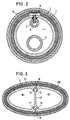
- Fig. 2 shows a cooling element in an embodiment in which an extruded profile 100 forms two channels 10, 10 ', which are separated by a partition 15.
- the channels 10 and 10 ' can be used, for example, to supply the liquid to be cooled or to discharge it.
- lines 11, 11 ' are integrated for supplying the liquid to be evaporated, which also lead in this example via capillary tubes 17 to a capillary layer 12 which is widened in the area of the outlet openings of the capillary tubes 17 and there guide plates 18 to has uniform distribution of the emerging liquid over the capillary layer 12.
- the capillary layer 12 is surrounded by a liquid barrier layer 13 of the same structure as the layer 3 in the exemplary embodiment according to FIGS. 1 and 2, and this in turn is surrounded by a support fabric corresponding to the support fabric 14 (FIG. 2) (in FIG. 3 not drawn).
- FIG. 3 shows only one of the manifold design options with regard to the cross-sectional configuration of a cooling element working with evaporative cooling according to the invention.
- This design option is also available in the longitudinal direction of the cooling elements, so that they can also be adapted to limited spatial conditions, such as are particularly present in spacecraft.
- the liquid barrier layer 3 or 13 can be dispensed with entirely if the capillary layer 2 or 12 and the liquid connector 7, 17 are designed such that the outer surface of the channels 1 is wetted solely by the capillary forces of liquid to be evaporated and the liquid is retained in the capillaries of the porous capillary layer 2 or 12 by the capillary forces.
Landscapes
- Engineering & Computer Science (AREA)
- Thermal Sciences (AREA)
- Physics & Mathematics (AREA)
- Mechanical Engineering (AREA)
- Health & Medical Sciences (AREA)
- General Engineering & Computer Science (AREA)
- General Health & Medical Sciences (AREA)
- Remote Sensing (AREA)
- Aviation & Aerospace Engineering (AREA)
- Emergency Medicine (AREA)
- Biodiversity & Conservation Biology (AREA)
- Environmental & Geological Engineering (AREA)
- Environmental Sciences (AREA)
- Toxicology (AREA)
- Life Sciences & Earth Sciences (AREA)
- Critical Care (AREA)
- Chemical & Material Sciences (AREA)
- Combustion & Propulsion (AREA)
- Heat-Exchange Devices With Radiators And Conduit Assemblies (AREA)
Applications Claiming Priority (2)
| Application Number | Priority Date | Filing Date | Title |
|---|---|---|---|
| DE3803534 | 1988-02-05 | ||
| DE3803534A DE3803534C1 (enExample) | 1988-02-05 | 1988-02-05 |
Publications (2)
| Publication Number | Publication Date |
|---|---|
| EP0326833A1 EP0326833A1 (de) | 1989-08-09 |
| EP0326833B1 true EP0326833B1 (de) | 1991-09-11 |
Family
ID=6346741
Family Applications (1)
| Application Number | Title | Priority Date | Filing Date |
|---|---|---|---|
| EP89100595A Expired - Lifetime EP0326833B1 (de) | 1988-02-05 | 1989-01-13 | Verdunstungskühler |
Country Status (4)
| Country | Link |
|---|---|
| US (1) | US4935169A (enExample) |
| EP (1) | EP0326833B1 (enExample) |
| JP (1) | JPH01310295A (enExample) |
| DE (2) | DE3803534C1 (enExample) |
Families Citing this family (22)
| Publication number | Priority date | Publication date | Assignee | Title |
|---|---|---|---|---|
| EP0458560B1 (en) * | 1990-05-21 | 1994-10-26 | Ishikawajima-Harima Jukogyo Kabushiki Kaisha | Heat protection element |
| US5050391A (en) * | 1991-01-18 | 1991-09-24 | Ari-Tec Marketing, Inc. | Method and apparatus for gas cooling |
| DE4130692C2 (de) * | 1991-09-14 | 1993-10-07 | Erno Raumfahrttechnik Gmbh | Verdampfungswärmetauscher |
| US5374381A (en) * | 1992-11-10 | 1994-12-20 | Rps Products, Inc. | Evaporative element for a humidifier and method of making the same |
| US5389311A (en) * | 1993-11-01 | 1995-02-14 | Hetzel; Henry T. | Atmometer covering and method |
| US6223548B1 (en) | 1998-03-20 | 2001-05-01 | General Shelters Of Texas, S.B., Inc. | Cooler housing apparatus and method of making the same |
| US6050101A (en) * | 1998-10-05 | 2000-04-18 | Nutec Electrical Engineering Co., Ltd. | High EER air conditioning apparatus with special heat exchanger |
| KR100409265B1 (ko) * | 2001-01-17 | 2003-12-18 | 한국과학기술연구원 | 재생형 증발식 냉방기 |
| GB0410850D0 (en) * | 2004-05-14 | 2004-06-16 | Cambridge Consultants | Cooling |
| US20070138662A1 (en) * | 2005-12-19 | 2007-06-21 | Chiu Peng C | Closed evaporative cooling tower |
| US20100032850A1 (en) * | 2008-08-05 | 2010-02-11 | Lin sui-ming | De-Fouling Tubes for Cooling Tower |
| US8943851B2 (en) | 2012-02-17 | 2015-02-03 | United Technologies Corporation | Evaporative cooler including one or more rotating cooler louvers |
| US9429346B2 (en) * | 2012-03-07 | 2016-08-30 | Aermist Llc | Evaporative chiller |
| US9599354B2 (en) | 2013-03-07 | 2017-03-21 | Aermist Llc | Evaporative HVAC apparatus |
| US9845960B2 (en) | 2012-03-07 | 2017-12-19 | Aermist Llc | Evaporative HVAC apparatus |
| US10343489B2 (en) | 2012-03-07 | 2019-07-09 | Nano Evaporative Technologies, Inc. | Evaporative HVAC apparatus |
| JP6130998B2 (ja) * | 2012-03-30 | 2017-05-17 | 三菱重工業株式会社 | 宇宙用冷却器 |
| US10704794B2 (en) | 2015-04-07 | 2020-07-07 | Brown University | Apparatus and method for passively cooling an interior |
| EP3844353A1 (en) | 2018-08-31 | 2021-07-07 | Techstyle Materials, Inc. | Multifunctional system for passive heat and water management |
| US20210300603A1 (en) * | 2020-03-25 | 2021-09-30 | Hamilton Sundstrand Corporation | Evaporators, liquid cooling ventilation garments with evaporators, and environmental control methods |
| CN115096017B (zh) * | 2022-05-30 | 2023-03-17 | 南京航空航天大学 | 一种结合毛细管的露点蒸发冷却器及方法 |
| CN116045704A (zh) * | 2023-03-03 | 2023-05-02 | 深圳市英维克科技股份有限公司 | 一种换热芯体片材及间接蒸发冷却板式换热器 |
Family Cites Families (8)
| Publication number | Priority date | Publication date | Assignee | Title |
|---|---|---|---|---|
| US1272937A (en) * | 1916-12-06 | 1918-07-16 | Samuel M Fulton | Refrigerator. |
| US2182788A (en) * | 1935-08-24 | 1939-12-12 | American Radiator & Standard | Means of cooling thermal medium |
| US2766597A (en) * | 1954-03-22 | 1956-10-16 | J F Pritchard Company | Heat exchange device for the evaporative cooling of a liquid |
| US3180111A (en) * | 1962-11-05 | 1965-04-27 | United Aircraft Corp | Combined insulating and cooling blanket |
| US3362186A (en) * | 1966-03-10 | 1968-01-09 | Albert S. Patterson | Cooling device for fluids |
| US4161212A (en) * | 1977-01-28 | 1979-07-17 | Martin Marietta Corporation | Pneumatically controlled wide heat load space radiator |
| GB2129924B (en) * | 1982-09-14 | 1986-03-05 | David Randolph Hine | Improvements in cooling apparatus for motor vehicles |
| US4674295A (en) * | 1983-03-14 | 1987-06-23 | Curtis Sr Thad C | Evaporative air conditioner and method |
-
1988
- 1988-02-05 DE DE3803534A patent/DE3803534C1/de not_active Expired
-
1989
- 1989-01-13 EP EP89100595A patent/EP0326833B1/de not_active Expired - Lifetime
- 1989-01-13 DE DE8989100595T patent/DE58900264D1/de not_active Expired - Lifetime
- 1989-01-25 US US07/301,141 patent/US4935169A/en not_active Expired - Fee Related
- 1989-02-06 JP JP1027345A patent/JPH01310295A/ja active Pending
Also Published As
| Publication number | Publication date |
|---|---|
| DE3803534C1 (enExample) | 1989-09-07 |
| DE58900264D1 (de) | 1991-10-17 |
| EP0326833A1 (de) | 1989-08-09 |
| JPH01310295A (ja) | 1989-12-14 |
| US4935169A (en) | 1990-06-19 |
Similar Documents
| Publication | Publication Date | Title |
|---|---|---|
| EP0326833B1 (de) | Verdunstungskühler | |
| DE3650658T2 (de) | Wärmetauscher | |
| DE69624984T2 (de) | Wärmeaustauschvorrichtung mit, mit Längslöchern versehenem, Metallband | |
| DE102005052683B4 (de) | Mehrkanalflachrohr für Wärmeübertrager | |
| DE2808854A1 (de) | Ein mit einbauten versehener stroemungskanal fuer ein an einem indirekten austausch, insbesondere waermeaustausch beteiligtes medium | |
| DE102010051517A1 (de) | Flugzeugaußenhautwärmetauscher, Flugzeugkühlsystem und Verfahren zum Betreiben eines Flugzeugaußenhautwärmetauschers | |
| DE10123456A1 (de) | Wärmetauscher | |
| EP0389623A1 (de) | Apparat zur indirekten verdampfungskühlung eines gases | |
| EP0029573A2 (de) | Wärmetauscher, deren Ausbildung und Anordnung in einer Einrichtung zur Wärmerückgewinnung durch Luftaustausch, insbesondere für Wohnhäuser und vergleichbare Anlagen | |
| EP3489603A1 (de) | Wärmetauscher | |
| DE69007709T2 (de) | Stapelverdampfer. | |
| DE4416616C2 (de) | Gehäuse | |
| EP0061697B1 (de) | Kältespeicherelement, Halterungen und Luftregellamellen dafür | |
| EP3249341B2 (de) | Wärmeaustauscher und verfahren zur benetzung von wärmeaustauschern | |
| DE3536316A1 (de) | Oelkuehler in scheibenbauweise | |
| DE10316073A1 (de) | Eine Hochtemperatur-Wärmeaustauschervorrichtung | |
| AT519899B1 (de) | Kühldeckenelement | |
| DE10328458A1 (de) | Niedrigtemperatur-Kühler für ein Kraftfahrzeug zur Kühlung mehrerer Bauteile | |
| DE102016216245A1 (de) | Anordnung zur Fluidtemperierung | |
| EP2562485A2 (de) | Medienheizer | |
| DE2219083C3 (de) | Absorptionskälteanlage | |
| EP3569953B1 (de) | Kältekreislaufvorrichtung und verfahren zum betrieb einer kältekreislaufvorrichtung mit einem hybridverdampfer | |
| EP0394758B1 (de) | Wärmetauscher | |
| DE102011082204A1 (de) | Thermoelektrische Einheit | |
| EP3161402B1 (de) | Wärmeübertrager |
Legal Events
| Date | Code | Title | Description |
|---|---|---|---|
| PUAI | Public reference made under article 153(3) epc to a published international application that has entered the european phase |
Free format text: ORIGINAL CODE: 0009012 |
|
| AK | Designated contracting states |
Kind code of ref document: A1 Designated state(s): DE FR GB IT |
|
| 17P | Request for examination filed |
Effective date: 19900206 |
|
| 17Q | First examination report despatched |
Effective date: 19901009 |
|
| GRAA | (expected) grant |
Free format text: ORIGINAL CODE: 0009210 |
|
| AK | Designated contracting states |
Kind code of ref document: B1 Designated state(s): DE FR GB IT |
|
| ITF | It: translation for a ep patent filed | ||
| REF | Corresponds to: |
Ref document number: 58900264 Country of ref document: DE Date of ref document: 19911017 |
|
| GBT | Gb: translation of ep patent filed (gb section 77(6)(a)/1977) | ||
| ET | Fr: translation filed | ||
| PLBE | No opposition filed within time limit |
Free format text: ORIGINAL CODE: 0009261 |
|
| STAA | Information on the status of an ep patent application or granted ep patent |
Free format text: STATUS: NO OPPOSITION FILED WITHIN TIME LIMIT |
|
| 26N | No opposition filed | ||
| PGFP | Annual fee paid to national office [announced via postgrant information from national office to epo] |
Ref country code: GB Payment date: 19960109 Year of fee payment: 8 |
|
| PGFP | Annual fee paid to national office [announced via postgrant information from national office to epo] |
Ref country code: DE Payment date: 19960110 Year of fee payment: 8 |
|
| PGFP | Annual fee paid to national office [announced via postgrant information from national office to epo] |
Ref country code: FR Payment date: 19960125 Year of fee payment: 8 |
|
| PG25 | Lapsed in a contracting state [announced via postgrant information from national office to epo] |
Ref country code: GB Effective date: 19970113 |
|
| GBPC | Gb: european patent ceased through non-payment of renewal fee |
Effective date: 19970113 |
|
| PG25 | Lapsed in a contracting state [announced via postgrant information from national office to epo] |
Ref country code: FR Effective date: 19970930 |
|
| PG25 | Lapsed in a contracting state [announced via postgrant information from national office to epo] |
Ref country code: DE Effective date: 19971001 |
|
| REG | Reference to a national code |
Ref country code: FR Ref legal event code: ST |
|
| PG25 | Lapsed in a contracting state [announced via postgrant information from national office to epo] |
Ref country code: IT Free format text: LAPSE BECAUSE OF NON-PAYMENT OF DUE FEES;WARNING: LAPSES OF ITALIAN PATENTS WITH EFFECTIVE DATE BEFORE 2007 MAY HAVE OCCURRED AT ANY TIME BEFORE 2007. THE CORRECT EFFECTIVE DATE MAY BE DIFFERENT FROM THE ONE RECORDED. Effective date: 20050113 |