EP0325548B1 - Faucheuse rotative comportant des organes de coupe s'étendant au-dessus d'un carter par l'intermédiaire de paliers de guidage et d'entraînement - Google Patents
Faucheuse rotative comportant des organes de coupe s'étendant au-dessus d'un carter par l'intermédiaire de paliers de guidage et d'entraînement Download PDFInfo
- Publication number
- EP0325548B1 EP0325548B1 EP89440003A EP89440003A EP0325548B1 EP 0325548 B1 EP0325548 B1 EP 0325548B1 EP 89440003 A EP89440003 A EP 89440003A EP 89440003 A EP89440003 A EP 89440003A EP 0325548 B1 EP0325548 B1 EP 0325548B1
- Authority
- EP
- European Patent Office
- Prior art keywords
- housing
- mower according
- casing
- holding element
- guiding
- Prior art date
- Legal status (The legal status is an assumption and is not a legal conclusion. Google has not performed a legal analysis and makes no representation as to the accuracy of the status listed.)
- Expired - Lifetime
Links
- 238000005520 cutting process Methods 0.000 title claims description 22
- 238000003466 welding Methods 0.000 description 6
- 230000002950 deficient Effects 0.000 description 5
- 239000000314 lubricant Substances 0.000 description 5
- 210000000056 organ Anatomy 0.000 description 5
- 238000000034 method Methods 0.000 description 3
- 230000000712 assembly Effects 0.000 description 2
- 238000000429 assembly Methods 0.000 description 2
- 239000002184 metal Substances 0.000 description 2
- 229910052751 metal Inorganic materials 0.000 description 2
- 238000003860 storage Methods 0.000 description 2
- 229910000746 Structural steel Inorganic materials 0.000 description 1
- 238000003287 bathing Methods 0.000 description 1
- 239000000470 constituent Substances 0.000 description 1
- 238000010276 construction Methods 0.000 description 1
- 230000006866 deterioration Effects 0.000 description 1
- 230000000694 effects Effects 0.000 description 1
- 239000000463 material Substances 0.000 description 1
- 238000012986 modification Methods 0.000 description 1
- 230000004048 modification Effects 0.000 description 1
- 238000003825 pressing Methods 0.000 description 1
- 230000001681 protective effect Effects 0.000 description 1
- 238000005096 rolling process Methods 0.000 description 1
- 125000006850 spacer group Chemical group 0.000 description 1
Images

Classifications
-
- A—HUMAN NECESSITIES
- A01—AGRICULTURE; FORESTRY; ANIMAL HUSBANDRY; HUNTING; TRAPPING; FISHING
- A01D—HARVESTING; MOWING
- A01D34/00—Mowers; Mowing apparatus of harvesters
- A01D34/01—Mowers; Mowing apparatus of harvesters characterised by features relating to the type of cutting apparatus
- A01D34/412—Mowers; Mowing apparatus of harvesters characterised by features relating to the type of cutting apparatus having rotating cutters
- A01D34/63—Mowers; Mowing apparatus of harvesters characterised by features relating to the type of cutting apparatus having rotating cutters having cutters rotating about a vertical axis
- A01D34/64—Mowers; Mowing apparatus of harvesters characterised by features relating to the type of cutting apparatus having rotating cutters having cutters rotating about a vertical axis mounted on a vehicle, e.g. a tractor, or drawn by an animal or a vehicle
- A01D34/66—Mowers; Mowing apparatus of harvesters characterised by features relating to the type of cutting apparatus having rotating cutters having cutters rotating about a vertical axis mounted on a vehicle, e.g. a tractor, or drawn by an animal or a vehicle with two or more cutters
- A01D34/664—Disc cutter bars
-
- F—MECHANICAL ENGINEERING; LIGHTING; HEATING; WEAPONS; BLASTING
- F16—ENGINEERING ELEMENTS AND UNITS; GENERAL MEASURES FOR PRODUCING AND MAINTAINING EFFECTIVE FUNCTIONING OF MACHINES OR INSTALLATIONS; THERMAL INSULATION IN GENERAL
- F16B—DEVICES FOR FASTENING OR SECURING CONSTRUCTIONAL ELEMENTS OR MACHINE PARTS TOGETHER, e.g. NAILS, BOLTS, CIRCLIPS, CLAMPS, CLIPS OR WEDGES; JOINTS OR JOINTING
- F16B39/00—Locking of screws, bolts or nuts
- F16B39/22—Locking of screws, bolts or nuts in which the locking takes place during screwing down or tightening
- F16B39/28—Locking of screws, bolts or nuts in which the locking takes place during screwing down or tightening by special members on, or shape of, the nut or bolt
-
- F—MECHANICAL ENGINEERING; LIGHTING; HEATING; WEAPONS; BLASTING
- F16—ENGINEERING ELEMENTS AND UNITS; GENERAL MEASURES FOR PRODUCING AND MAINTAINING EFFECTIVE FUNCTIONING OF MACHINES OR INSTALLATIONS; THERMAL INSULATION IN GENERAL
- F16L—PIPES; JOINTS OR FITTINGS FOR PIPES; SUPPORTS FOR PIPES, CABLES OR PROTECTIVE TUBING; MEANS FOR THERMAL INSULATION IN GENERAL
- F16L55/00—Devices or appurtenances for use in, or in connection with, pipes or pipe systems
- F16L55/18—Appliances for use in repairing pipes
Definitions
- the present invention relates to a mower provided with a cutter bar comprising cutting members extending above a casing and each of which is guided and rotated around an axis directed upwards by a bearing of guide and drive which comprises a housing centered in a corresponding bore in the upper part of the housing, a guide bearing mounted in said housing and a shaft guided in said housing using the guide bearing, said shaft being provided at its upper end with a fixing part for fixing the corresponding cutting member and at its lower end with a toothed wheel extending inside the casing and meshing with at least one other toothed wheel also housed inside said casing, said first toothed wheel having an outside diameter less than the diameter of the corresponding bore formed in the upper part of the casing, each of said guide and drive bearings being fixed to the upper part of the casing by assembly members comprising screws whose rod comes out of the upper part of the casing and nuts screwed onto said rods, said casing being formed by said upper part and a lower part removably assembled by assembly elements.
- This known mower comprises a cutter bar provided with rotary cutting discs which extend above a casing formed by two parts: an upper part and a lower part removably assembled to each other by means of assembly elements. Each rotary cutting disc is guided and rotated around an axis directed upwards by a guide and drive bearing (see Spare Parts catalog, pages 10 to 13).
- Each guide and drive bearing comprises a housing centered in a corresponding bore made in the upper part of the housing, a bearing guide mounted in said housing and consisting of two bearings, and a shaft guided in the housing using the guide bearing, this shaft being provided at its upper end with a fixing part for fixing the corresponding cutting disc and at its lower end of a toothed wheel having an outside diameter less than the diameter of the corresponding bore formed in the upper part of the casing.
- Each guide and drive bearing is fixed to the upper part of the housing by assembly members of the screw-nut type, comprising screws the head of which extends inside the housing and the stem of which comes out of the upper part of the casing through holes provided for this purpose.
- the rod of each screw also passes through a respective hole provided in the flange of the guide and drive bearing, and on its end emerging from the flange is screwed a nut after interposition of a support washer. Since the screws are not kept rotating, it is necessary, to effect the change of a guide and drive bearing, to disassemble the lower part of the casing to block the rotation of the screws, in order to be able to loosen, then tighten the nuts screwed onto the rod of said screws.
- the sheet constituting the upper part of the casing can deform during welding, so that after welding, the rods of the screws are not parallel to each other, which will cause problems in passing them through the through holes in the housing of the corresponding guide and drive bearing.
- a second drawback is that, given the length of the upper parts of the casing, handling them to weld the screws is not easy.
- each guide and drive bearing is fixed to the casing by assembly members of the screw-nut type. These each include a "JAPY” type screw provided with a round head under which is provided a square section flange intended to immobilize the rotating screw. The head of the screw extends at the end of the casing and rests on the bottom of the lower part of the casing while its square flange is housed in a hole of similar shape made in the lower part of the casing.
- the screw rod then passes through a spacer extending inside the housing between the lower part and the upper part of the housing, then a hole provided in the upper part of the housing and finally a hole provided in the flange of the housing of the guide and drive bearing.
- a nut On the end of the rod leaving the flange is screwed a nut after interposition of a support washer.
- each guide and drive bearing is as well attached to the upper part as to the lower part of the casing.
- This binding is therefore particularly resistant.
- it gives very good rigidity to the casing so that this method of construction is particularly suitable for mower cutter bars intended to be heavily stressed during work.
- This arrangement also makes it possible to change a guide and drive bearing without it being necessary, for this to open the casing. Besides, it will also be very easy to replace an accidentally damaged screw.
- This arrangement however requires the provision of through holes for the screws in the lower part of the casing. As the sump contains a lubricant in which bathe the gears, it will therefore also be necessary to provide a seal at each screw to avoid leakage of lubricant.
- a mounting device using screw-nut assemblies of objects on the walls of plastic parts in particular for mounting casters on the bottom of rolling bins.
- Each roller has at its upper part a plate pierced with four holes which coincide with four corresponding holes made in the bottom of the tank.
- Each screw-nut assembly is according to a first embodiment consisting of a rod folded at a right angle at its ends, the folded parts comprising threads.
- a metal plate is provided on one face of which are fixed by welding threaded rods.
- a metal plate is provided in which two holes have been made in which engage and are fixed by welding screws having a head and a threaded body.
- an angle iron having holes in which screws are mounted, each comprising a hexagonal head and a threaded part.
- the screw heads are not fixed to the angle, but their dimensions are adapted to the spacing between the vertical wings of the angle.
- the screws used to fix the guide and drive bearings on the upper part of the housing will only be put in place when the cutter bar is assembled. Consequently, these screws cannot be damaged during storage or handling of the upper part of the housing. It is then possible to loosen and tighten the nuts screwed onto these screws without it being necessary to disassemble the lower part of the casing, since the holding member prevents rotation of the corresponding screw.
- the holding member maintains the corresponding screw substantially in its appropriate position so that the guide and drive bearing can be easily mounted and that the screw does not risk falling into the casing when the guide and drive bearing has been dismantled.
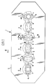
- FIG 1 a mower (1) which comprises a cutter bar (2) extending in a known manner under a protective device (3).
- the device for linking said cutter bar (2) has not been shown to a tractor vehicle. Such devices are in fact within the reach of those skilled in the art.
- the cutter bar (2) comprises in a nonlimiting manner six cutting members (4, 5) each rotating around an axis (450) (see FIGS. 2 and 3) directed upwards, for example in the directions (6 , 7).
- Each cutting member (4, 5) is provided with two knives (8) and extends above a casing (9) in which it is guided in rotation and which contains drive members (10) ( Figures 2 and 3) for driving in rotation of said cutting members (4, 5).
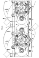
- the casing (9) is formed by an upper part (11) and a lower part (12) which are assembled to one another by means of assembly elements ( 13). After assembly, the two parts (11, 12) determine a substantially rectangular space (14) which contains the drive members (10).
- These drive members (10) are, in the example shown, constituted by a cascade of cylindrical toothed wheels (15) and intermediate cylindrical toothed wheels (16) meshing with each other and rotating in a lubricant.
- Each toothed wheel (15) is linked at the lower end (17) of a shaft (18) by means of grooves (19) and a nut (20).
- the shaft (18) is linked to a fixing part (22).
- This fixing part (22) makes it possible to fix the cutting member (4, 5) corresponding to the shaft (18) and this by means of screws (23).
- the shaft (18) is guided in rotation in a guide bearing (24) which is, in the example shown, constituted by a bearing with two rows of angular contact balls.
- This guide bearing (24) is itself mounted in a housing (25) and is connected to it in translation by a shoulder (26) and a circlip (27).
- the housing (25) is centered in a corresponding bore (28) formed in the upper part (11) of the casing (9) and is fixed to said upper part (11) by means of assembly members (29).
- the diameter of the bore (28) is larger than the outside diameter of the corresponding toothed wheel (15), but smaller than the outside diameter of the flange (25) of the housing (25).
- the assembly consisting of a housing (25), the corresponding guide bearing (24), the circlip (27) serving to link this guide bearing (24) to the housing (25), the corresponding shaft (18), the corresponding fixing part (22), the corresponding toothed wheel (15) and the nut (20), therefore forms a guide and drive bearing (30) which can be mounted or removed from the casing (9) from above since the outside diameter of the toothed wheel (15) is smaller than the diameter of the corresponding bore (28).
- the assembly members (29) serving to fix a housing (25) on the upper part (11) of the casing (9) notably comprise screws (31) and nuts (32) .
- each housing (25) is fixed by means of four sets of screws (31) - nut (32).
- Each screw (31) has its head (33) which extends inside the parallelepipedal space (14) and its rod (34) which exits from the upper part (11) of the casing (9) by passing through a hole (35) corresponding for this purpose in the upper part (11).
- the screws (31) are fixed (in the example shown by welding) to holding members (36).
- each holding member (36) is provided with two screws (31) so that by housing (25), there are two holding members (36).
- Each holding member (36) is constituted by a bracket, one wing (37) of which extends substantially horizontally and supports the screws (31) and the other wing (38) of which extends substantially vertically between the upper part (11 ) and the lower part (12) of the casing (9).
- the height of the holding member (36) that is to say in the example shown, the length of the vertical wing (38), is substantially equal to the internal thickness of the casing (9).
- each holding member (36) is provided with two screws (31) and the fixing of each guide and drive bearing (30) therefore requires two sets of holding member (36) - screw (31).
- these retaining members (36) extend substantially parallel to the longitudinal axis of the casing (9), so as to allow engagement between the corresponding toothed wheel (15) and the intermediate wheels (16) neighbors.
- the horizontal wing (37) of a holding member (36) has a circular recess (39) centered on the axis of rotation (450) of the toothed wheel (15 ) corresponding and of a radius slightly larger than the radius of said toothed wheel (15).
- the rod (34) of a screw (31) exits from the upper part (11) of the casing (9) said rod (34) is provided with 'a groove (340) approximately semi-circular in which is mounted an O-ring (341).
- the corresponding passage hole (251) provided in the flange (250) of the corresponding housing (25) comprises, at the point where it opens onto the face of said flange (250) intended to come into contact with the upper part (11) of the casing (9), an important chamfer (252).
- the O-ring (341) fills the space created between the groove (340) and the corresponding chamfer. (252) and thereby provides a perfect seal preventing any leakage of lubricant contained in the housing (9).
- the fixing part (22) of each guide and drive bearing (30) allowing the fixing of the corresponding cutting member (4, 5).
- this shape is such that the nuts (32) used for fixing a guide and drive bearing (30) on the upper part (11) of the casing (9) are easily accessible from above.
- the fixing part (22) has four flats (40) which give said fixing part (22) in top view a generally substantially square shape.
- This special shape allows simultaneous access to the four nuts (32) so that it will be possible to use special screwdrivers with four tightening heads for simultaneous tightening of the four nuts (32).
- the cutter bar (2) which has just been described above can be used in a conventional mower, in a mower-swather or in a mower-conditioner.
Landscapes
- Engineering & Computer Science (AREA)
- General Engineering & Computer Science (AREA)
- Mechanical Engineering (AREA)
- Life Sciences & Earth Sciences (AREA)
- Environmental Sciences (AREA)
- Harvester Elements (AREA)
Priority Applications (1)
| Application Number | Priority Date | Filing Date | Title |
|---|---|---|---|
| AT89440003T ATE80969T1 (de) | 1988-01-22 | 1989-01-18 | Kreiselmaeher mit maehorganen, die mittels lagern an der oberseite eines gehaeuses angeordnet sind. |
Applications Claiming Priority (2)
| Application Number | Priority Date | Filing Date | Title |
|---|---|---|---|
| FR8800901A FR2626137B1 (fr) | 1988-01-22 | 1988-01-22 | Faucheuse rotative comportant des organes de coupe s'etendant au-dessus d'un carter par l'intermediaire de paliers de guidage et d'entrainement |
| FR8800901 | 1988-01-22 |
Publications (2)
| Publication Number | Publication Date |
|---|---|
| EP0325548A1 EP0325548A1 (fr) | 1989-07-26 |
| EP0325548B1 true EP0325548B1 (fr) | 1992-09-30 |
Family
ID=9362669
Family Applications (1)
| Application Number | Title | Priority Date | Filing Date |
|---|---|---|---|
| EP89440003A Expired - Lifetime EP0325548B1 (fr) | 1988-01-22 | 1989-01-18 | Faucheuse rotative comportant des organes de coupe s'étendant au-dessus d'un carter par l'intermédiaire de paliers de guidage et d'entraînement |
Country Status (8)
| Country | Link |
|---|---|
| US (1) | US4922693A (da) |
| EP (1) | EP0325548B1 (da) |
| JP (1) | JP2753515B2 (da) |
| AT (1) | ATE80969T1 (da) |
| DE (1) | DE68902997T2 (da) |
| DK (1) | DK174154B1 (da) |
| ES (1) | ES2034733T3 (da) |
| FR (1) | FR2626137B1 (da) |
Families Citing this family (16)
| Publication number | Priority date | Publication date | Assignee | Title |
|---|---|---|---|---|
| FR2638056B1 (fr) * | 1988-10-26 | 1991-06-07 | Kuhn Sa | Faucheuse avec montage perfectionne des organes de coupe |
| US5012635A (en) * | 1990-06-01 | 1991-05-07 | Deere & Company | Modular cutterbar for rotary mower |
| FR2675980B1 (fr) * | 1991-04-30 | 1998-07-03 | Kuhn Sa | Machine de coupe perfectionnee avec structure d'attelage pivotante. |
| FR2724689B1 (fr) * | 1994-09-16 | 1997-01-24 | Kuhn Sa | Mecanisme de verrouillage destine a equiper principalement une machine agricole |
| FR2736505B1 (fr) * | 1995-07-13 | 1997-09-26 | Kuhn Sa | Faucheuse avec un dispositif d'andainage perfectionne |
| FR2743978B1 (fr) * | 1996-01-31 | 1998-04-17 | Kuhn Sa | Faucheuse avec organe de depose perfectionne |
| FR2748187B1 (fr) * | 1996-05-02 | 1998-07-31 | Kuhn Sa | Machine de coupe comportant des moyens simplifies permettant de la deposer et de l'atteler a un vehicule moteur |
| FR2767633B1 (fr) * | 1997-09-02 | 1999-10-08 | Kuhn Sa | Dispositif de conditionnement ameliore, machine pour le conditionnement et faucheuse conditionneuse comportant un tel dispositif |
| DE19827072A1 (de) * | 1998-06-18 | 1999-12-30 | Krone Bernhard Gmbh Maschf | Mähmaschine |
| FR2774853B1 (fr) | 1999-02-15 | 2001-02-16 | Kuhn Sa | Organe de coupe pour une machine de coupe notamment une faucheuse |
| FR2794934B1 (fr) | 1999-06-17 | 2001-08-10 | Kuhn Sa | Machine agricole du type faucheuse ou faucheuse- conditionnneuse comportant un organe d'amortissement |
| FR2802766B1 (fr) | 1999-12-23 | 2002-09-27 | Kuhn Sa | Element de coupe d'une machine de coupe de vegetaux rotative et machine de coupe de vegetaux rotative comportant un tel element de coupe |
| FR2830167B1 (fr) * | 2001-10-03 | 2004-07-30 | Kuhn Sa | Machine agricole, notamment du type faucheuse rotative, comportant un dispositif de coupe ameliore |
| FR2913301B1 (fr) * | 2007-03-05 | 2011-07-15 | Alain Quenard | Broyeur de paille a six rotors a axes verticaux disposes en ligne |
| US7661253B2 (en) * | 2007-12-19 | 2010-02-16 | Agco Corporation | Modular rotary cutterbar |
| US7730703B1 (en) | 2009-08-24 | 2010-06-08 | Cnh America Llc | Modular disc cutterbar |
Citations (1)
| Publication number | Priority date | Publication date | Assignee | Title |
|---|---|---|---|---|
| FR2518672A1 (fr) * | 1981-12-18 | 1983-06-24 | Plastic Omnium Cie | Dispositif de montage a l'aide d'ensembles vis-ecrou d'objets sur des parois de pieces en matiere plastique et bacs roulants utilisant un tel dispositif pour le montage de roulettes |
Family Cites Families (14)
| Publication number | Priority date | Publication date | Assignee | Title |
|---|---|---|---|---|
| US593505A (en) * | 1897-11-09 | Rail joint | ||
| US2568928A (en) * | 1949-12-29 | 1951-09-25 | Deere Mfg Co | Bolt retainer and attaching structure for agricultural tractors and implements |
| FR1483721A (fr) * | 1965-04-09 | 1967-06-09 | Appareil faucheur | |
| NL171319B (nl) | 1973-12-28 | 1982-10-18 | Multinorm Bv | Aan een voertuig te bevestigen maaiinrichting. |
| GB2002622B (en) * | 1977-08-18 | 1982-01-20 | Sperry Rand Ltd | Disc mowers |
| FR2474811A1 (fr) * | 1980-02-04 | 1981-08-07 | Kuhn Sa | Barre de coupe perfectionnee |
| FR2496391A1 (fr) * | 1980-12-19 | 1982-06-25 | Kuhn Sa | Perfectionnement aux faucheuses |
| US4740124A (en) * | 1981-12-28 | 1988-04-26 | United Technologies Corporation | Threaded insert |
| NL8203461A (nl) * | 1982-09-06 | 1984-04-02 | Lely Nv C Van Der | Maaiinrichting voor landbouwdoeleinden. |
| US4466234A (en) * | 1982-11-22 | 1984-08-21 | Sasaki Nouki Kabushiki Kaisha | Disk mower |
| DE3243351A1 (de) * | 1982-11-24 | 1984-05-24 | Friedrich Mörtl Schleppergerätebau GmbH & Co KG, 8780 Gemünden | Traggehaeuse fuer tellermaeher |
| FR2570248B1 (fr) * | 1984-09-19 | 1990-06-29 | Kuhn Sa | Faucheuse rotative |
| US4787196A (en) * | 1986-03-31 | 1988-11-29 | New Holland Inc. | Self-cleaning rotor assembly |
| EP0240084B1 (en) * | 1986-03-31 | 1992-09-02 | FORD NEW HOLLAND, INC. (a Delaware corp.) | Gear mounting apparatus and disc cutter rotor assembly |
-
1988
- 1988-01-22 FR FR8800901A patent/FR2626137B1/fr not_active Expired - Fee Related
-
1989
- 1989-01-18 DK DK198900201A patent/DK174154B1/da not_active IP Right Cessation
- 1989-01-18 EP EP89440003A patent/EP0325548B1/fr not_active Expired - Lifetime
- 1989-01-18 AT AT89440003T patent/ATE80969T1/de not_active IP Right Cessation
- 1989-01-18 DE DE8989440003T patent/DE68902997T2/de not_active Expired - Fee Related
- 1989-01-18 ES ES198989440003T patent/ES2034733T3/es not_active Expired - Lifetime
- 1989-01-23 US US07/299,450 patent/US4922693A/en not_active Expired - Lifetime
- 1989-01-23 JP JP1013888A patent/JP2753515B2/ja not_active Expired - Fee Related
Patent Citations (1)
| Publication number | Priority date | Publication date | Assignee | Title |
|---|---|---|---|---|
| FR2518672A1 (fr) * | 1981-12-18 | 1983-06-24 | Plastic Omnium Cie | Dispositif de montage a l'aide d'ensembles vis-ecrou d'objets sur des parois de pieces en matiere plastique et bacs roulants utilisant un tel dispositif pour le montage de roulettes |
Non-Patent Citations (1)
| Title |
|---|
| Catalogue Massey-Fergusson, MF 51, 1730670 M1, 5/70 * |
Also Published As
| Publication number | Publication date |
|---|---|
| US4922693A (en) | 1990-05-08 |
| EP0325548A1 (fr) | 1989-07-26 |
| DK174154B1 (da) | 2002-07-29 |
| DE68902997D1 (de) | 1992-11-05 |
| DK20189A (da) | 1989-07-23 |
| JP2753515B2 (ja) | 1998-05-20 |
| ES2034733T3 (es) | 1993-04-01 |
| DK20189D0 (da) | 1989-01-18 |
| ATE80969T1 (de) | 1992-10-15 |
| DE68902997T2 (de) | 1993-09-16 |
| FR2626137B1 (fr) | 1991-09-06 |
| FR2626137A1 (fr) | 1989-07-28 |
| JPH01225414A (ja) | 1989-09-08 |
Similar Documents
| Publication | Publication Date | Title |
|---|---|---|
| EP0325548B1 (fr) | Faucheuse rotative comportant des organes de coupe s'étendant au-dessus d'un carter par l'intermédiaire de paliers de guidage et d'entraînement | |
| EP0171341B1 (fr) | Faucheuse rotative | |
| EP0408088B1 (fr) | Faucheuse rotative | |
| FR2474811A1 (fr) | Barre de coupe perfectionnee | |
| FR2739059A1 (fr) | Moyeu de roue notamment pour cycle | |
| FR2466669A2 (fr) | Roue libre de cycle, ainsi que la roue de cycle pour son montage | |
| FR2680746A1 (fr) | Moyeu arriere en plusieurs parties pour bicyclettes. | |
| FR2565311A1 (fr) | Raccordement de chaine directrice sur une roue d'entrainement orientable d'un chariot de manutention | |
| FR2785561A1 (fr) | Compresseur de ressort pour ressorts helicoidaux avec au moins un disque de ressort | |
| EP0839558B1 (fr) | Patin à roulettes en ligne | |
| EP0299859B1 (fr) | Dispositif de commande de direction arrière pour véhicule automobile à quatre roues directrices | |
| EP4171888B1 (fr) | Outillage pour permettre la fixation d'un moyen de protection sous un véhicule et procédé de montage associé | |
| EP0135459A1 (fr) | Faucheuse à disques perfectionnée | |
| EP0677404B1 (fr) | Essieu d'entraînement et de réglage en hauteur des roues motrices d'une machine autotractée à paliers démontables et machine équipée de cet essieu | |
| FR3051427A1 (fr) | Berceau de vehicule automobile comprenant une premiere partie et une seconde partie et des moyens de fixation | |
| FR2669502A1 (fr) | Machine pour travailler le sol a unites de travail entrainees en rotation par des arbres verticaux, et comprenant une dent elastique centrale. | |
| CH691323A5 (fr) | Etai. | |
| FR2825320A1 (fr) | Moyeu de roue et roue ayant un tel moyeu | |
| FR2735819A1 (fr) | Dispositif de liaison mecanique entre une barre tubulaire et une piece d'ancrage et son application a une structure de satellitte artificiel | |
| FR2562841A1 (fr) | Tableau d'ecriture utilisant des feuilles de papier | |
| FR2712767A1 (fr) | Machine de fenaison transposable dans plusieurs positions de travail. | |
| FR2754233A1 (fr) | Volant de direction et colonne adaptee au montage d'un tel volant | |
| BE835126A (fr) | Manchon adaptateur notamment pour le montage de roues de vehicules automobiles | |
| FR2858029A1 (fr) | Ecrou a grande flottabilite | |
| FR2613580A1 (fr) | Faucheuse rotative |
Legal Events
| Date | Code | Title | Description |
|---|---|---|---|
| PUAI | Public reference made under article 153(3) epc to a published international application that has entered the european phase |
Free format text: ORIGINAL CODE: 0009012 |
|
| AK | Designated contracting states |
Kind code of ref document: A1 Designated state(s): AT BE DE ES FR GB IT NL |
|
| 17P | Request for examination filed |
Effective date: 19891207 |
|
| 17Q | First examination report despatched |
Effective date: 19910318 |
|
| GRAA | (expected) grant |
Free format text: ORIGINAL CODE: 0009210 |
|
| AK | Designated contracting states |
Kind code of ref document: B1 Designated state(s): AT BE DE ES FR GB IT NL |
|
| REF | Corresponds to: |
Ref document number: 80969 Country of ref document: AT Date of ref document: 19921015 Kind code of ref document: T |
|
| ITF | It: translation for a ep patent filed | ||
| REF | Corresponds to: |
Ref document number: 68902997 Country of ref document: DE Date of ref document: 19921105 |
|
| GBT | Gb: translation of ep patent filed (gb section 77(6)(a)/1977) | ||
| REG | Reference to a national code |
Ref country code: ES Ref legal event code: FG2A Ref document number: 2034733 Country of ref document: ES Kind code of ref document: T3 |
|
| PLBE | No opposition filed within time limit |
Free format text: ORIGINAL CODE: 0009261 |
|
| STAA | Information on the status of an ep patent application or granted ep patent |
Free format text: STATUS: NO OPPOSITION FILED WITHIN TIME LIMIT |
|
| 26N | No opposition filed | ||
| REG | Reference to a national code |
Ref country code: GB Ref legal event code: IF02 |
|
| PGFP | Annual fee paid to national office [announced via postgrant information from national office to epo] |
Ref country code: IT Payment date: 20060131 Year of fee payment: 18 |
|
| PGFP | Annual fee paid to national office [announced via postgrant information from national office to epo] |
Ref country code: NL Payment date: 20061227 Year of fee payment: 19 Ref country code: DE Payment date: 20061227 Year of fee payment: 19 Ref country code: AT Payment date: 20061227 Year of fee payment: 19 |
|
| PGFP | Annual fee paid to national office [announced via postgrant information from national office to epo] |
Ref country code: GB Payment date: 20061228 Year of fee payment: 19 |
|
| PGFP | Annual fee paid to national office [announced via postgrant information from national office to epo] |
Ref country code: BE Payment date: 20070105 Year of fee payment: 19 |
|
| PGFP | Annual fee paid to national office [announced via postgrant information from national office to epo] |
Ref country code: ES Payment date: 20070116 Year of fee payment: 19 |
|
| PGFP | Annual fee paid to national office [announced via postgrant information from national office to epo] |
Ref country code: FR Payment date: 20070129 Year of fee payment: 19 |
|
| BERE | Be: lapsed |
Owner name: S.A. *KUHN Effective date: 20080131 |
|
| GBPC | Gb: european patent ceased through non-payment of renewal fee |
Effective date: 20080118 |
|
| NLV4 | Nl: lapsed or anulled due to non-payment of the annual fee |
Effective date: 20080801 |
|
| PG25 | Lapsed in a contracting state [announced via postgrant information from national office to epo] |
Ref country code: DE Free format text: LAPSE BECAUSE OF NON-PAYMENT OF DUE FEES Effective date: 20080801 Ref country code: NL Free format text: LAPSE BECAUSE OF NON-PAYMENT OF DUE FEES Effective date: 20080801 |
|
| PG25 | Lapsed in a contracting state [announced via postgrant information from national office to epo] |
Ref country code: AT Free format text: LAPSE BECAUSE OF NON-PAYMENT OF DUE FEES Effective date: 20080118 |
|
| REG | Reference to a national code |
Ref country code: FR Ref legal event code: ST Effective date: 20081029 |
|
| PG25 | Lapsed in a contracting state [announced via postgrant information from national office to epo] |
Ref country code: GB Free format text: LAPSE BECAUSE OF NON-PAYMENT OF DUE FEES Effective date: 20080118 |
|
| PG25 | Lapsed in a contracting state [announced via postgrant information from national office to epo] |
Ref country code: BE Free format text: LAPSE BECAUSE OF NON-PAYMENT OF DUE FEES Effective date: 20080131 |
|
| REG | Reference to a national code |
Ref country code: ES Ref legal event code: FD2A Effective date: 20080119 |
|
| PG25 | Lapsed in a contracting state [announced via postgrant information from national office to epo] |
Ref country code: FR Free format text: LAPSE BECAUSE OF NON-PAYMENT OF DUE FEES Effective date: 20080131 |
|
| PG25 | Lapsed in a contracting state [announced via postgrant information from national office to epo] |
Ref country code: ES Free format text: LAPSE BECAUSE OF NON-PAYMENT OF DUE FEES Effective date: 20080119 |
|
| PG25 | Lapsed in a contracting state [announced via postgrant information from national office to epo] |
Ref country code: IT Free format text: LAPSE BECAUSE OF NON-PAYMENT OF DUE FEES Effective date: 20070118 |