EP0325064B1 - Verbesserung der Stabilität von Gabelhubwagen mit einem teleskopischen Arm - Google Patents
Verbesserung der Stabilität von Gabelhubwagen mit einem teleskopischen Arm Download PDFInfo
- Publication number
- EP0325064B1 EP0325064B1 EP19880403018 EP88403018A EP0325064B1 EP 0325064 B1 EP0325064 B1 EP 0325064B1 EP 19880403018 EP19880403018 EP 19880403018 EP 88403018 A EP88403018 A EP 88403018A EP 0325064 B1 EP0325064 B1 EP 0325064B1
- Authority
- EP
- European Patent Office
- Prior art keywords
- telescopic arm
- arm
- stability
- forklift truck
- telescopic
- Prior art date
- Legal status (The legal status is an assumption and is not a legal conclusion. Google has not performed a legal analysis and makes no representation as to the accuracy of the status listed.)
- Expired - Lifetime
Links
- 238000010586 diagram Methods 0.000 description 6
- 230000005484 gravity Effects 0.000 description 6
- 230000005540 biological transmission Effects 0.000 description 3
- 238000006073 displacement reaction Methods 0.000 description 3
- 230000009286 beneficial effect Effects 0.000 description 1
- 108010066057 cabin-1 Proteins 0.000 description 1
- 230000008878 coupling Effects 0.000 description 1
- 238000010168 coupling process Methods 0.000 description 1
- 238000005859 coupling reaction Methods 0.000 description 1
- 230000002706 hydrostatic effect Effects 0.000 description 1
- 238000009434 installation Methods 0.000 description 1
- 230000003068 static effect Effects 0.000 description 1
Images


Classifications
-
- B—PERFORMING OPERATIONS; TRANSPORTING
- B66—HOISTING; LIFTING; HAULING
- B66F—HOISTING, LIFTING, HAULING OR PUSHING, NOT OTHERWISE PROVIDED FOR, e.g. DEVICES WHICH APPLY A LIFTING OR PUSHING FORCE DIRECTLY TO THE SURFACE OF A LOAD
- B66F9/00—Devices for lifting or lowering bulky or heavy goods for loading or unloading purposes
- B66F9/06—Devices for lifting or lowering bulky or heavy goods for loading or unloading purposes movable, with their loads, on wheels or the like, e.g. fork-lift trucks
- B66F9/065—Devices for lifting or lowering bulky or heavy goods for loading or unloading purposes movable, with their loads, on wheels or the like, e.g. fork-lift trucks non-masted
- B66F9/0655—Devices for lifting or lowering bulky or heavy goods for loading or unloading purposes movable, with their loads, on wheels or the like, e.g. fork-lift trucks non-masted with a telescopic boom
Definitions
- the present invention relates to self-propelled forklifts of the type comprising a single telescopic arm, articulated in the rear half of the chassis (see Figures 1 and 2).
- This telescopic arm is provided with a hydraulic lifting cylinder which is, in general, placed under the telescopic beam, between the beam and the structure of the machine.
- the front end of said telescopic arm comprises means for coupling specific tools for handling loads, such as forks, skips, jibs, etc.
- Trolleys of this type are mostly equipped with an oscillating landing axle, which is used to improve comfort and stability in dynamics, in particular in all terrains.
- a bracket is provided formed by two fixed pillars articulated around the articulation axis on which the telescopic beam is hung.
- Said telescopic beam can be positioned around the articulation axis as in French patent n ° 2 287 413 or immediately below (see FIG. 1) in order to facilitate the installation of the foot of a jack, called telescoping, which allows you to exit and return the telescopic element of the beam.
- the telescopic beam is therefore characterized by the raised position of its rear part and the bottom of its front part. This arrangement has two drawbacks.
- the first is that the telescopic beam largely crosses the driver's lateral field of vision (see Figure 1) in the natural position of transporting a load, thus dangerously affecting the driver's visibility.
- the second is that it causes a large displacement, in rotation towards the rear of the center of gravity of the telescopic beam during lifting at great height. This significant displacement of the masses of the telescope towards the rear of the machine is unfavorable to its transverse stability towards the rear. Now, the transverse backward stability obeys a standard and tests aimed at giving these machines an abacus of lifting capacities acceptable for their safety of use.
- the invention aims to remedy these drawbacks and to provide a new arrangement of the telescopic arm of a forklift which thus improves the lifting performance for a given power.
- the self-propelled carriage of the telescopic arm type articulated under a bracket formed by two pillars articulated around an articulation axis is characterized in that the telescopic arm is offset downward relative to the articulation axis of a distance (d) substantially equal to 40% of the height of the articulation axis relative to the ground.
- d a distance substantially equal to 40% of the height of the articulation axis relative to the ground.
- the elevation axis of the beam meanwhile, will remain at a height substantially as high as that of traditional telehandlers. Only the telescopic arm will be lowered very significantly with respect to its axis of articulation by means of a structure in the form of a butt whose upper end is crossed by the axis of articulation of elevation.
- the latter will be in the low position below the driver's field of vision, thereby improving its lateral visibility.
- the telescopic lifting cylinder (s) can be placed on the sides of the telescopic beam, thus freeing up additional space, space which, in a traditional design , is occupied by the lifting cylinder.
- the invention can be applied to forklifts with traditional architecture in which the telescopic arm passes over the powertrain centered on the chassis. In this case, a significant improvement in stability and visibility is already obtained.
- the gain in stability and visibility is increased when the invention is applied to forklifts in which all the bulky members (powerplant, transmission, cabin) have been arranged so as to release entirely the median longitudinal axis of the carriage to accommodate the telescopic arm.
- the cabin 1 is arranged on one side of the carriage between the front 9 and rear wheels 10
- the motor 2 is arranged between the opposite wheels 9 and 10 of the on the other side of the chassis, the assembly completely freeing a central platform for the arm 6 which can thus be arranged as low as possible.
- the telescopic arm 6 generally consists of 2 to 3 sections, the end of the internal section carrying an apron 7 for attaching tools such as forks (shown in this example), buckets, concrete buckets, etc. ..
- the transmission between the engine and the front axle 11 is a hydrostatic transmission.
- the bracket 4 is disposed substantially at the level of the rear axle 11.
- the arm 6 is pendulous under the upper end of the bracket 4 which is made up of two pillars 17 supporting a transverse shaft 18.
- the offset between the articulation axis 18 and with the longitudinal axis of the telescopic arm 3 is represented by the arrow d in FIG. 3. It is obtained by the general structure of the arm 6 in the form of a butt at the rear end of the external telescope.
- This offset structure d makes it possible to considerably increase the stability of the trolley for identical lifting heights and loads and, as a corollary, it makes it possible to increase the lifting capacities, with identical safety coefficient.
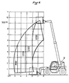
- This improvement in capacities clearly appears during the comparison of FIGS. 5 and 6 where FIG. 5 represents the load chart of a current carriage and FIG. 6 that of a carriage of the same dimension produced according to the invention.
- each amount of said bracket carries a point of articulation 19 for a jack 20 whose end of the rod is articulated on a yoke 21 fixed on the top of the outer tube of the arm 6
- this arrangement ensures a lowering of the center of gravity of the arm, which further enhances the improvement in lifting performance.
- the center of gravity G2 of the beam according to the invention is constantly lower or more advanced than the center of gravity G1 of a conventional beam, throughout the elevation movement.
- FIG. 7 shows the gains in stability induced by a telescopic beam according to the invention during a complete lifting movement.
- a i (initial) represents the difference between G2 and G1 in the low position.
- a 1, A 2 ... A 6 represent the gains obtained during the elevation and ⁇ f (final) the gain of lifting, at maximum height.
Landscapes
- Engineering & Computer Science (AREA)
- Transportation (AREA)
- Structural Engineering (AREA)
- Civil Engineering (AREA)
- Life Sciences & Earth Sciences (AREA)
- Geology (AREA)
- Mechanical Engineering (AREA)
- Forklifts And Lifting Vehicles (AREA)
Claims (6)
Applications Claiming Priority (2)
| Application Number | Priority Date | Filing Date | Title |
|---|---|---|---|
| FR8717728A FR2624842B1 (fr) | 1987-12-18 | 1987-12-18 | Amelioration a la stabilite des chariots elevateurs a bras telescopique |
| FR8717728 | 1987-12-18 |
Publications (2)
| Publication Number | Publication Date |
|---|---|
| EP0325064A1 EP0325064A1 (de) | 1989-07-26 |
| EP0325064B1 true EP0325064B1 (de) | 1990-08-08 |
Family
ID=9358045
Family Applications (1)
| Application Number | Title | Priority Date | Filing Date |
|---|---|---|---|
| EP19880403018 Expired - Lifetime EP0325064B1 (de) | 1987-12-18 | 1988-11-30 | Verbesserung der Stabilität von Gabelhubwagen mit einem teleskopischen Arm |
Country Status (4)
| Country | Link |
|---|---|
| EP (1) | EP0325064B1 (de) |
| DE (1) | DE3860446D1 (de) |
| ES (1) | ES2017797B3 (de) |
| FR (1) | FR2624842B1 (de) |
Cited By (2)
| Publication number | Priority date | Publication date | Assignee | Title |
|---|---|---|---|---|
| DE102004018644A1 (de) * | 2004-04-16 | 2005-11-03 | Liebherr-Werk Nenzing Gmbh, Nenzing | Telelader, insbesondere Reachstacker |
| KR20160037765A (ko) * | 2014-09-29 | 2016-04-06 | 제이씨 뱀포드 엑스카베이터즈 리미티드 | 요 방향 조정 수단을 가진 붐 조립체 |
Families Citing this family (10)
| Publication number | Priority date | Publication date | Assignee | Title |
|---|---|---|---|---|
| CA2009968C (en) * | 1990-02-13 | 1996-06-25 | Giovanni Bentivoglio | Boom operated fork truck |
| JPH04131574U (ja) * | 1991-05-29 | 1992-12-03 | 谷電機工業株式会社 | 重心保持と重心移動機能付運搬装置 |
| DE9114464U1 (de) * | 1991-11-21 | 1993-03-25 | Krupp Industrietechnik GmbH, 4100 Duisburg | Kranfahrzeug |
| DE9302376U1 (de) * | 1993-02-18 | 1993-06-24 | EC Engineering + Consulting Spezialmaschinen GmbH, 7900 Ulm | Kranfahrzeug |
| CA2153955C (en) * | 1994-07-15 | 2005-01-11 | John Moses | Material-handling vehicle |
| FR2724374B1 (fr) * | 1994-09-14 | 1996-10-25 | Manitou Bf | Chariot de manutention motorise apte a etre embarque a l'arriere d'un vehicule porteur |
| EP0701963B2 (de) * | 1994-09-14 | 2004-08-18 | Manitou Bf | Motorhubwagen mit teleskopischem Arm |
| FR2728884A1 (fr) * | 1995-01-04 | 1996-07-05 | Manitou Bf | Chariot de manutention motorise a bras telescopique |
| FR2788759B1 (fr) | 1999-01-27 | 2001-03-23 | Sambron | Dispositif de controle de deplacement d'une structure portante d'engin roulant et engin roulant incorporant ledit dispositif |
| DE102004021839A1 (de) | 2004-05-04 | 2005-12-01 | Liebherr-Werk Nenzing Gmbh, Nenzing | Telelader, insbesondere Reachstacker |
Family Cites Families (7)
| Publication number | Priority date | Publication date | Assignee | Title |
|---|---|---|---|---|
| US3270899A (en) * | 1964-04-17 | 1966-09-06 | Baldwin Lima Hamilton Corp | Load handling vehicle |
| FR2091898B1 (de) * | 1970-04-09 | 1978-01-13 | Potain Sa | |
| US3836025A (en) * | 1973-05-21 | 1974-09-17 | Loed Corp | Material-handling machine |
| US3985248A (en) * | 1974-09-25 | 1976-10-12 | Badger Dynamics, Inc. | Telescopic boom assembly |
| DE2545427B2 (de) * | 1974-10-12 | 1979-05-03 | Liner Concrete Machinery Co. Ltd., Gateshead, Durham (Grossbritannien) | Fahrzeug zum Umsetzen von Lasten |
| US4147263A (en) * | 1977-01-06 | 1979-04-03 | Lull Engineering Company, Inc. | High lift loader with extended transfer |
| IT1102219B (it) * | 1978-02-02 | 1985-10-07 | Comensoli Cormach | Apparecchiatura di sollevamento a due bracci |
-
1987
- 1987-12-18 FR FR8717728A patent/FR2624842B1/fr not_active Expired - Lifetime
-
1988
- 1988-11-30 ES ES88403018T patent/ES2017797B3/es not_active Expired - Lifetime
- 1988-11-30 EP EP19880403018 patent/EP0325064B1/de not_active Expired - Lifetime
- 1988-11-30 DE DE8888403018T patent/DE3860446D1/de not_active Expired - Lifetime
Cited By (2)
| Publication number | Priority date | Publication date | Assignee | Title |
|---|---|---|---|---|
| DE102004018644A1 (de) * | 2004-04-16 | 2005-11-03 | Liebherr-Werk Nenzing Gmbh, Nenzing | Telelader, insbesondere Reachstacker |
| KR20160037765A (ko) * | 2014-09-29 | 2016-04-06 | 제이씨 뱀포드 엑스카베이터즈 리미티드 | 요 방향 조정 수단을 가진 붐 조립체 |
Also Published As
| Publication number | Publication date |
|---|---|
| EP0325064A1 (de) | 1989-07-26 |
| DE3860446D1 (de) | 1990-09-13 |
| ES2017797B3 (es) | 1991-03-01 |
| FR2624842B1 (fr) | 1990-04-06 |
| FR2624842A1 (fr) | 1989-06-23 |
Similar Documents
| Publication | Publication Date | Title |
|---|---|---|
| EP0325064B1 (de) | Verbesserung der Stabilität von Gabelhubwagen mit einem teleskopischen Arm | |
| EP0440519B1 (de) | Hubwagen mit teleskopischem Ausleger | |
| EP0701963B2 (de) | Motorhubwagen mit teleskopischem Arm | |
| BE1014630A3 (fr) | Engin de manutention de type diable. | |
| EP0905083B1 (de) | Wagen mit Hubmast, geeignet zur Montage an das Ende eines Transportfahrzeugs | |
| FR2800363A1 (fr) | Chariot elevateur a fourche | |
| FR2472536A1 (fr) | Vehicule utilitaire a usages multiples | |
| EP0000295B1 (de) | Hubstapler | |
| EP0100926B1 (de) | Fahrzeug zur Handhabung von Materialien mit orientierbarem Ausleger und eingebautem Stabilisiergestell | |
| FR2681216A1 (fr) | Vehicule permettant d'assurer le prelevement (coupe, ramassage et stockage) d'herbes ou produits similaires, et enceinte de stockage adaptable a des vehicules existants. | |
| FR2690883A1 (fr) | Mécanisme d'actionnement pour le bras arrière basculant de levage/tractage d'un véhicule de dépannage. | |
| FR2615157A1 (fr) | Tracteur perfectionne notamment pour semi-remorque | |
| FR2536735A1 (fr) | Chariot de travail notamment pour la pose des vitres de toitures des serres agricoles | |
| FR2480209A1 (fr) | Vehicule pour le transport de bois en grume | |
| FR2765865A1 (fr) | Vehicule de manutention de materiaux | |
| FR2768422A1 (fr) | Structure de support pour vehicule monte sur roues | |
| FR2509114A1 (fr) | Perfectionnements aux machines a vendanger automotrices | |
| FR2791049A1 (fr) | Porte equipement pour engin de levage, mat d'un engin de levage comprenant un tel porte equipement et engin de levage tel que chariot a fourches pourvu dudit mat | |
| EP0012095B1 (de) | Selbststabilisierendes Fahrzeug zum Heben und zur Handhabung von Lasten | |
| FR2580563A1 (fr) | Dispositif pour manipuler une charge notamment pour vehicules de transport | |
| CH350781A (fr) | Grue | |
| FR2782949A1 (fr) | Dispositif de roulement pour engin agricole | |
| FR2810613A1 (fr) | Dispositif a leviers de renvoi pour le relevage des fourches d'un chariot de type transpalette | |
| FR2458508A1 (fr) | Chariot elevateur a fourche muni de moyens de transfert horizontal longitudinal | |
| EP4635894A1 (de) | Kran mit aufhebbarem ausleger |
Legal Events
| Date | Code | Title | Description |
|---|---|---|---|
| PUAI | Public reference made under article 153(3) epc to a published international application that has entered the european phase |
Free format text: ORIGINAL CODE: 0009012 |
|
| AK | Designated contracting states |
Kind code of ref document: A1 Designated state(s): BE DE ES GB IT LU NL |
|
| 17P | Request for examination filed |
Effective date: 19890619 |
|
| 17Q | First examination report despatched |
Effective date: 19891017 |
|
| GRAA | (expected) grant |
Free format text: ORIGINAL CODE: 0009210 |
|
| AK | Designated contracting states |
Kind code of ref document: B1 Designated state(s): BE DE ES GB IT LU NL |
|
| REF | Corresponds to: |
Ref document number: 3860446 Country of ref document: DE Date of ref document: 19900913 |
|
| ITF | It: translation for a ep patent filed | ||
| GBT | Gb: translation of ep patent filed (gb section 77(6)(a)/1977) | ||
| PLBE | No opposition filed within time limit |
Free format text: ORIGINAL CODE: 0009261 |
|
| STAA | Information on the status of an ep patent application or granted ep patent |
Free format text: STATUS: NO OPPOSITION FILED WITHIN TIME LIMIT |
|
| 26N | No opposition filed | ||
| PGFP | Annual fee paid to national office [announced via postgrant information from national office to epo] |
Ref country code: LU Payment date: 19921014 Year of fee payment: 5 |
|
| PGFP | Annual fee paid to national office [announced via postgrant information from national office to epo] |
Ref country code: BE Payment date: 19921029 Year of fee payment: 5 |
|
| PGFP | Annual fee paid to national office [announced via postgrant information from national office to epo] |
Ref country code: GB Payment date: 19921120 Year of fee payment: 5 Ref country code: ES Payment date: 19921120 Year of fee payment: 5 |
|
| PGFP | Annual fee paid to national office [announced via postgrant information from national office to epo] |
Ref country code: DE Payment date: 19921126 Year of fee payment: 5 |
|
| ITTA | It: last paid annual fee | ||
| PGFP | Annual fee paid to national office [announced via postgrant information from national office to epo] |
Ref country code: NL Payment date: 19921130 Year of fee payment: 5 |
|
| EPTA | Lu: last paid annual fee | ||
| PG25 | Lapsed in a contracting state [announced via postgrant information from national office to epo] |
Ref country code: LU Free format text: LAPSE BECAUSE OF NON-PAYMENT OF DUE FEES Effective date: 19931130 Ref country code: GB Effective date: 19931130 Ref country code: BE Effective date: 19931130 |
|
| PG25 | Lapsed in a contracting state [announced via postgrant information from national office to epo] |
Ref country code: ES Free format text: LAPSE BECAUSE OF THE APPLICANT RENOUNCES Effective date: 19931201 |
|
| BERE | Be: lapsed |
Owner name: MANITOU BF Effective date: 19931130 |
|
| PG25 | Lapsed in a contracting state [announced via postgrant information from national office to epo] |
Ref country code: NL Effective date: 19940601 |
|
| NLV4 | Nl: lapsed or anulled due to non-payment of the annual fee | ||
| GBPC | Gb: european patent ceased through non-payment of renewal fee |
Effective date: 19931130 |
|
| PG25 | Lapsed in a contracting state [announced via postgrant information from national office to epo] |
Ref country code: DE Effective date: 19940802 |
|
| REG | Reference to a national code |
Ref country code: ES Ref legal event code: FD2A Effective date: 20010402 |
|
| PG25 | Lapsed in a contracting state [announced via postgrant information from national office to epo] |
Ref country code: IT Free format text: LAPSE BECAUSE OF NON-PAYMENT OF DUE FEES Effective date: 20051130 |