EP0325064A1 - Verbesserung der Stabilität von Gabelhubwagen mit einem teleskopischen Arm - Google Patents
Verbesserung der Stabilität von Gabelhubwagen mit einem teleskopischen Arm Download PDFInfo
- Publication number
- EP0325064A1 EP0325064A1 EP88403018A EP88403018A EP0325064A1 EP 0325064 A1 EP0325064 A1 EP 0325064A1 EP 88403018 A EP88403018 A EP 88403018A EP 88403018 A EP88403018 A EP 88403018A EP 0325064 A1 EP0325064 A1 EP 0325064A1
- Authority
- EP
- European Patent Office
- Prior art keywords
- telescopic arm
- arm
- forklift
- telescopic
- stability
- Prior art date
- Legal status (The legal status is an assumption and is not a legal conclusion. Google has not performed a legal analysis and makes no representation as to the accuracy of the status listed.)
- Granted
Links
Images
Classifications
-
- B—PERFORMING OPERATIONS; TRANSPORTING
- B66—HOISTING; LIFTING; HAULING
- B66F—HOISTING, LIFTING, HAULING OR PUSHING, NOT OTHERWISE PROVIDED FOR, e.g. DEVICES WHICH APPLY A LIFTING OR PUSHING FORCE DIRECTLY TO THE SURFACE OF A LOAD
- B66F9/00—Devices for lifting or lowering bulky or heavy goods for loading or unloading purposes
- B66F9/06—Devices for lifting or lowering bulky or heavy goods for loading or unloading purposes movable, with their loads, on wheels or the like, e.g. fork-lift trucks
- B66F9/065—Devices for lifting or lowering bulky or heavy goods for loading or unloading purposes movable, with their loads, on wheels or the like, e.g. fork-lift trucks non-masted
- B66F9/0655—Devices for lifting or lowering bulky or heavy goods for loading or unloading purposes movable, with their loads, on wheels or the like, e.g. fork-lift trucks non-masted with a telescopic boom
Definitions
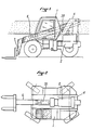
- the present invention relates to self-propelled forklifts of the type comprising a single telescopic arm, articulated in the rear half of the frame (see Figures 1 and 2).
- This telescopic arm is provided with a hydraulic lift cylinder which is, in general, placed under the telescopic beam, between the beam and the structure of the machine.
- the front end of said telescopic arm comprises means for hitching specific tools for handling loads, such as forks, buckets, stems, etc.
- Trucks of this type are for the most part equipped with an oscillating rear axle, which serves to improve comfort and stability in dynamics, especially in all terrains.
- the present trolleys are characterized in that, in order to improve the lifting heights while maintaining a reasonable overall length, the lifting hinge pin of the telescopic beam is in an elevated position relative to the rest of the machine, sometimes even above the level of the driver's head.
- the telescopic beam meanwhile, is positioned immediately above or below this axis, and this to allow the implantation of the foot of the cylinder, said telescoping, which allows exit and retract the telescopic element of the beam.
- the telescopic beam is therefore characterized by the raised position of its rear and lower part of its front part. This arrangement has two disadvantages.
- the first is that the telescopic beam extensively crosses the lateral field of view of the driver (see Figure 1) in the natural position of transport of a load, thus dangerously affecting the visibility of the driver.
- the second is that it causes a large displacement, rotating backwards of the center of gravity of the telescopic beam during lifts high.
- This significant displacement of the masses of the telescope towards the rear of the machine is unfavorable to its transverse stability towards the rear.
- the transverse stability towards the rear obeys a standard and tests aiming at conferring on these machines an abacus of lifting capacities acceptable for their safety of use.
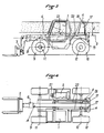
- the telescopic arm carriage which comprises in a known manner a frame, a heat engine and a transmission, a cockpit and a lifting arm hinged to the rear of the frame, is characterized in that the arm is offset downwardly relative to the hinge pin lift.
- the arm is offset downwardly relative to the hinge pin lift.
- the telescope lifting jack (s) can be placed on the sides of the telescopic beam, thus freeing up additional space, space which, in a traditional design , is occupied by the lift cylinder.
- the hinge axis of elevation of the beam meanwhile, will remain at a height substantially as high as that of traditional telescopic carriages. Only the telescopic arm will be lowered significantly relative to its axis of articulation by means of a butt-shaped structure whose upper end is traversed by the axis of articulation of elevation.
- the invention is therefore characterized by a significant offset of the telescopic beam relative to its axis of articulation. This offset can reach or even exceed 40% of the height of the axis of articulation relative to the ground.
- the invention can be applied to traditionally-built lift trucks in which the telescopic arm passes over the power train centered on the chassis. In this case we already obtain a significant improvement in stability as well as visibility.
- the gain in stability and visibility is increased when the invention is applied to lift trucks in which all the bulky members (powertrain, transmission, cab) have been arranged in such a way as to disengage completely.
- the median longitudinal axis of the carriage to accommodate the telescopic arm.
- the cab 1 is disposed on one side of the carriage between the front wheels 9 and rear 10
- the motor 2 is disposed between the opposite wheels 9 and 10 of the other side of the frame, the assembly completely releasing a central platform for the arm 6 which can be arranged as low as possible.
- the telescopic arm 6 is generally constituted of 2 to 3 sections, the end of the inner section carrying an attachment apron 7 of tools such as forks (shown in this example), buckets, concrete buckets, etc. ..
- the transmission between the engine and the front axle 11 is a hydrostatic transmission.
- the stem 4 is disposed substantially at the level of the rear axle 11.
- the arm 6 is pendulum under the upper end of the bracket 4 which consists of two pillars 17 articulated around a transverse shaft 18.
- the offset between the axis of articulation 18 and with the longitudinal axis of the telescopic arm 3 is represented by the arrow d in FIG. 3. It is obtained by the general structure of the arm 6 in the shape of a stick at the rear end. of the external telescope.
- each upright of said bracket carries a hinge point 19 for a cylinder 20 whose end of the rod is articulated on a yoke 21 fixed on the top of the outer tube of the arm 6
- this arrangement ensures a lowering of the center of gravity of the arm, which further enhances the improvement of lifting performance.
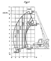
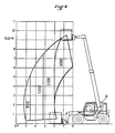
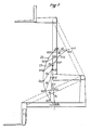
- FIG. 7 is a schematic diagram showing the trajectories of the centers of gravity of the two types of telescopic beams: . a traditional beam (reference 22) . a beam according to the invention (reference 23)
- the center of gravity G2 of the beam according to the invention is constantly lower or more advanced than the center of gravity G1 of a conventional beam during the entire lifting movement.
- FIG. 7 shows the stability gains induced by a telescopic beam according to the invention during a movement complete lifting.
- ⁇ i (initial) represents the difference between G2 and G1 in the low position.
- ⁇ 1, ⁇ 2 ... ⁇ 6 represent the gains obtained during the elevation and ⁇ f (final) the lift gain finally, at maximum height.
Landscapes
- Engineering & Computer Science (AREA)
- Transportation (AREA)
- Structural Engineering (AREA)
- Civil Engineering (AREA)
- Life Sciences & Earth Sciences (AREA)
- Geology (AREA)
- Mechanical Engineering (AREA)
- Forklifts And Lifting Vehicles (AREA)
Applications Claiming Priority (2)
| Application Number | Priority Date | Filing Date | Title |
|---|---|---|---|
| FR8717728 | 1987-12-18 | ||
| FR8717728A FR2624842B1 (fr) | 1987-12-18 | 1987-12-18 | Amelioration a la stabilite des chariots elevateurs a bras telescopique |
Publications (2)
| Publication Number | Publication Date |
|---|---|
| EP0325064A1 true EP0325064A1 (de) | 1989-07-26 |
| EP0325064B1 EP0325064B1 (de) | 1990-08-08 |
Family
ID=9358045
Family Applications (1)
| Application Number | Title | Priority Date | Filing Date |
|---|---|---|---|
| EP19880403018 Expired - Lifetime EP0325064B1 (de) | 1987-12-18 | 1988-11-30 | Verbesserung der Stabilität von Gabelhubwagen mit einem teleskopischen Arm |
Country Status (4)
| Country | Link |
|---|---|
| EP (1) | EP0325064B1 (de) |
| DE (1) | DE3860446D1 (de) |
| ES (1) | ES2017797B3 (de) |
| FR (1) | FR2624842B1 (de) |
Cited By (10)
| Publication number | Priority date | Publication date | Assignee | Title |
|---|---|---|---|---|
| EP0543276A1 (de) * | 1991-11-21 | 1993-05-26 | Krupp Industrietechnik Gmbh | Fahrzeugkran |
| AU647625B2 (en) * | 1991-05-29 | 1994-03-24 | Tani Electronics Industry Co., Ltd. | Transporter with function of maintaining and moving centre of gravity |
| EP0611725A1 (de) * | 1993-02-18 | 1994-08-24 | EC Engineering + Consulting Spezialmaschinen GmbH | Kranfahrzeug |
| EP0692448A1 (de) * | 1994-07-15 | 1996-01-17 | J.C. Bamford Excavators Limited | Handhabungsfahrzeug für Material |
| FR2724374A1 (fr) * | 1994-09-14 | 1996-03-15 | Manitou Bf | Chariot de manutention motorise apte a etre embarque a l'arriere d'un vehicule porteur |
| EP0701963A1 (de) * | 1994-09-14 | 1996-03-20 | Manitou Bf | Motorhubwagen mit teleskopischem Arm |
| FR2728884A1 (fr) * | 1995-01-04 | 1996-07-05 | Manitou Bf | Chariot de manutention motorise a bras telescopique |
| EP1024108A1 (de) | 1999-01-27 | 2000-08-02 | Sambron | Vorrichtung zur Umstellungskontrolle einer Tragstruktur eines Wagens |
| EP1593643A2 (de) | 2004-05-04 | 2005-11-09 | Liebherr-Werk Nenzing GmbH | Telelader, insbesondere Reachstacker |
| US20160090282A1 (en) * | 2014-09-29 | 2016-03-31 | J. C. Bamford Excavators Limited | Boom assembly with yaw adjustment |
Families Citing this family (2)
| Publication number | Priority date | Publication date | Assignee | Title |
|---|---|---|---|---|
| CA2009968C (en) * | 1990-02-13 | 1996-06-25 | Giovanni Bentivoglio | Boom operated fork truck |
| DE102004018644A1 (de) * | 2004-04-16 | 2005-11-03 | Liebherr-Werk Nenzing Gmbh, Nenzing | Telelader, insbesondere Reachstacker |
Citations (7)
| Publication number | Priority date | Publication date | Assignee | Title |
|---|---|---|---|---|
| FR1435214A (fr) * | 1964-04-17 | 1966-04-15 | Baldwin Lima Hamilton Corp | Véhicule de manutention auto-chargeur |
| FR2091898A1 (de) * | 1970-04-09 | 1971-01-21 | Potain Sa | |
| FR2287413A1 (fr) * | 1974-10-12 | 1976-05-07 | Liner Concrete Machinery | Perfectionnements a des vehicules de manutention de charges |
| US3985248A (en) * | 1974-09-25 | 1976-10-12 | Badger Dynamics, Inc. | Telescopic boom assembly |
| US4147263A (en) * | 1977-01-06 | 1979-04-03 | Lull Engineering Company, Inc. | High lift loader with extended transfer |
| USRE30021E (en) * | 1973-05-21 | 1979-06-05 | Loed Corporation | Material handling machine |
| GB2013616A (en) * | 1978-02-02 | 1979-08-15 | Comensoli Cormach | Double slewing crane |
-
1987
- 1987-12-18 FR FR8717728A patent/FR2624842B1/fr not_active Expired - Lifetime
-
1988
- 1988-11-30 ES ES88403018T patent/ES2017797B3/es not_active Expired - Lifetime
- 1988-11-30 EP EP19880403018 patent/EP0325064B1/de not_active Expired - Lifetime
- 1988-11-30 DE DE8888403018T patent/DE3860446D1/de not_active Expired - Lifetime
Patent Citations (7)
| Publication number | Priority date | Publication date | Assignee | Title |
|---|---|---|---|---|
| FR1435214A (fr) * | 1964-04-17 | 1966-04-15 | Baldwin Lima Hamilton Corp | Véhicule de manutention auto-chargeur |
| FR2091898A1 (de) * | 1970-04-09 | 1971-01-21 | Potain Sa | |
| USRE30021E (en) * | 1973-05-21 | 1979-06-05 | Loed Corporation | Material handling machine |
| US3985248A (en) * | 1974-09-25 | 1976-10-12 | Badger Dynamics, Inc. | Telescopic boom assembly |
| FR2287413A1 (fr) * | 1974-10-12 | 1976-05-07 | Liner Concrete Machinery | Perfectionnements a des vehicules de manutention de charges |
| US4147263A (en) * | 1977-01-06 | 1979-04-03 | Lull Engineering Company, Inc. | High lift loader with extended transfer |
| GB2013616A (en) * | 1978-02-02 | 1979-08-15 | Comensoli Cormach | Double slewing crane |
Cited By (18)
| Publication number | Priority date | Publication date | Assignee | Title |
|---|---|---|---|---|
| AU647625B2 (en) * | 1991-05-29 | 1994-03-24 | Tani Electronics Industry Co., Ltd. | Transporter with function of maintaining and moving centre of gravity |
| EP0543276A1 (de) * | 1991-11-21 | 1993-05-26 | Krupp Industrietechnik Gmbh | Fahrzeugkran |
| EP0611725A1 (de) * | 1993-02-18 | 1994-08-24 | EC Engineering + Consulting Spezialmaschinen GmbH | Kranfahrzeug |
| US5405028A (en) * | 1993-02-18 | 1995-04-11 | Ec Engineering+Consulting Spezialmaschinen Gmbh | Crane vehicle |
| EP0692448A1 (de) * | 1994-07-15 | 1996-01-17 | J.C. Bamford Excavators Limited | Handhabungsfahrzeug für Material |
| US5836733A (en) * | 1994-07-15 | 1998-11-17 | J.C. Bamford Excavators Limited | Material-handling vehicle |
| US5813821A (en) * | 1994-09-14 | 1998-09-29 | Manitou Bf | Motorized lift truck adapted to be loaded on the rear of a carrying vehicle |
| EP0701963A1 (de) * | 1994-09-14 | 1996-03-20 | Manitou Bf | Motorhubwagen mit teleskopischem Arm |
| FR2724374A1 (fr) * | 1994-09-14 | 1996-03-15 | Manitou Bf | Chariot de manutention motorise apte a etre embarque a l'arriere d'un vehicule porteur |
| FR2728884A1 (fr) * | 1995-01-04 | 1996-07-05 | Manitou Bf | Chariot de manutention motorise a bras telescopique |
| EP1024108A1 (de) | 1999-01-27 | 2000-08-02 | Sambron | Vorrichtung zur Umstellungskontrolle einer Tragstruktur eines Wagens |
| EP1593643A2 (de) | 2004-05-04 | 2005-11-09 | Liebherr-Werk Nenzing GmbH | Telelader, insbesondere Reachstacker |
| EP1593643A3 (de) * | 2004-05-04 | 2011-05-04 | Liebherr-Werk Nenzing GmbH | Telelader, insbesondere Reachstacker |
| US20160090282A1 (en) * | 2014-09-29 | 2016-03-31 | J. C. Bamford Excavators Limited | Boom assembly with yaw adjustment |
| KR20160037765A (ko) * | 2014-09-29 | 2016-04-06 | 제이씨 뱀포드 엑스카베이터즈 리미티드 | 요 방향 조정 수단을 가진 붐 조립체 |
| CN105460808A (zh) * | 2014-09-29 | 2016-04-06 | J.C.班福德挖掘机有限公司 | 具有偏转调节的吊臂组件 |
| US10106384B2 (en) * | 2014-09-29 | 2018-10-23 | J. C. Bamford Excavators Limited | Boom assembly with yaw adjustment |
| KR102139264B1 (ko) * | 2014-09-29 | 2020-07-29 | 제이씨 뱀포드 엑스카베이터즈 리미티드 | 요 방향 조정 수단을 가진 붐 조립체 |
Also Published As
| Publication number | Publication date |
|---|---|
| EP0325064B1 (de) | 1990-08-08 |
| ES2017797B3 (es) | 1991-03-01 |
| DE3860446D1 (de) | 1990-09-13 |
| FR2624842A1 (fr) | 1989-06-23 |
| FR2624842B1 (fr) | 1990-04-06 |
Similar Documents
| Publication | Publication Date | Title |
|---|---|---|
| EP0739286B1 (de) | Selbstlenkungsarm eines strassenfahrzeugs entlang einer leitschiene | |
| EP0325064B1 (de) | Verbesserung der Stabilität von Gabelhubwagen mit einem teleskopischen Arm | |
| EP0375705A1 (de) | Hebewagen mit einem teleskopischen hebearm. | |
| EP0440519B1 (de) | Hubwagen mit teleskopischem Ausleger | |
| EP0701963B2 (de) | Motorhubwagen mit teleskopischem Arm | |
| BE1014630A3 (fr) | Engin de manutention de type diable. | |
| EP1849744B1 (de) | Förderwagen mit mindestens drei Leiträdern | |
| EP0000295B1 (de) | Hubstapler | |
| FR2681216A1 (fr) | Vehicule permettant d'assurer le prelevement (coupe, ramassage et stockage) d'herbes ou produits similaires, et enceinte de stockage adaptable a des vehicules existants. | |
| EP0100926B1 (de) | Fahrzeug zur Handhabung von Materialien mit orientierbarem Ausleger und eingebautem Stabilisiergestell | |
| FR2690883A1 (fr) | Mécanisme d'actionnement pour le bras arrière basculant de levage/tractage d'un véhicule de dépannage. | |
| EP0414836B1 (de) | Fahrzeug mit verstellbarer lenkradgeometrie | |
| FR2670840A1 (fr) | Actionneur d'articulation pour la mise en óoeuvre de tous mouvements rectilignes ou rotatifs. | |
| FR2655921A1 (fr) | Vehicule bivalent apte a la marche sur route et sur rail. | |
| FR2765865A1 (fr) | Vehicule de manutention de materiaux | |
| EP2910513A1 (de) | Hebevorrichtung mit einer Regulierung der Höhenlage | |
| FR2509114A1 (fr) | Perfectionnements aux machines a vendanger automotrices | |
| FR2750125A1 (fr) | Chariot elevateur pour preparation de commandes | |
| FR2768422A1 (fr) | Structure de support pour vehicule monte sur roues | |
| FR2653294A1 (fr) | Attelage compose d'un tracteur et d'un chariot attele a l'avant de celui-ci. | |
| FR2810613A1 (fr) | Dispositif a leviers de renvoi pour le relevage des fourches d'un chariot de type transpalette | |
| FR2782949A1 (fr) | Dispositif de roulement pour engin agricole | |
| EP0012095B1 (de) | Selbststabilisierendes Fahrzeug zum Heben und zur Handhabung von Lasten | |
| CH350781A (fr) | Grue | |
| FR2755681A1 (fr) | Chariot elevateur a dispositif de stabilisateur |
Legal Events
| Date | Code | Title | Description |
|---|---|---|---|
| PUAI | Public reference made under article 153(3) epc to a published international application that has entered the european phase |
Free format text: ORIGINAL CODE: 0009012 |
|
| AK | Designated contracting states |
Kind code of ref document: A1 Designated state(s): BE DE ES GB IT LU NL |
|
| 17P | Request for examination filed |
Effective date: 19890619 |
|
| 17Q | First examination report despatched |
Effective date: 19891017 |
|
| GRAA | (expected) grant |
Free format text: ORIGINAL CODE: 0009210 |
|
| AK | Designated contracting states |
Kind code of ref document: B1 Designated state(s): BE DE ES GB IT LU NL |
|
| REF | Corresponds to: |
Ref document number: 3860446 Country of ref document: DE Date of ref document: 19900913 |
|
| ITF | It: translation for a ep patent filed | ||
| GBT | Gb: translation of ep patent filed (gb section 77(6)(a)/1977) | ||
| PLBE | No opposition filed within time limit |
Free format text: ORIGINAL CODE: 0009261 |
|
| STAA | Information on the status of an ep patent application or granted ep patent |
Free format text: STATUS: NO OPPOSITION FILED WITHIN TIME LIMIT |
|
| 26N | No opposition filed | ||
| PGFP | Annual fee paid to national office [announced via postgrant information from national office to epo] |
Ref country code: LU Payment date: 19921014 Year of fee payment: 5 |
|
| PGFP | Annual fee paid to national office [announced via postgrant information from national office to epo] |
Ref country code: BE Payment date: 19921029 Year of fee payment: 5 |
|
| PGFP | Annual fee paid to national office [announced via postgrant information from national office to epo] |
Ref country code: GB Payment date: 19921120 Year of fee payment: 5 Ref country code: ES Payment date: 19921120 Year of fee payment: 5 |
|
| PGFP | Annual fee paid to national office [announced via postgrant information from national office to epo] |
Ref country code: DE Payment date: 19921126 Year of fee payment: 5 |
|
| ITTA | It: last paid annual fee | ||
| PGFP | Annual fee paid to national office [announced via postgrant information from national office to epo] |
Ref country code: NL Payment date: 19921130 Year of fee payment: 5 |
|
| EPTA | Lu: last paid annual fee | ||
| PG25 | Lapsed in a contracting state [announced via postgrant information from national office to epo] |
Ref country code: LU Free format text: LAPSE BECAUSE OF NON-PAYMENT OF DUE FEES Effective date: 19931130 Ref country code: GB Effective date: 19931130 Ref country code: BE Effective date: 19931130 |
|
| PG25 | Lapsed in a contracting state [announced via postgrant information from national office to epo] |
Ref country code: ES Free format text: LAPSE BECAUSE OF THE APPLICANT RENOUNCES Effective date: 19931201 |
|
| BERE | Be: lapsed |
Owner name: MANITOU BF Effective date: 19931130 |
|
| PG25 | Lapsed in a contracting state [announced via postgrant information from national office to epo] |
Ref country code: NL Effective date: 19940601 |
|
| NLV4 | Nl: lapsed or anulled due to non-payment of the annual fee | ||
| GBPC | Gb: european patent ceased through non-payment of renewal fee |
Effective date: 19931130 |
|
| PG25 | Lapsed in a contracting state [announced via postgrant information from national office to epo] |
Ref country code: DE Effective date: 19940802 |
|
| REG | Reference to a national code |
Ref country code: ES Ref legal event code: FD2A Effective date: 20010402 |
|
| PG25 | Lapsed in a contracting state [announced via postgrant information from national office to epo] |
Ref country code: IT Free format text: LAPSE BECAUSE OF NON-PAYMENT OF DUE FEES Effective date: 20051130 |