EP0324899B1 - Badewanneneinsatz - Google Patents
Badewanneneinsatz Download PDFInfo
- Publication number
- EP0324899B1 EP0324899B1 EP88117429A EP88117429A EP0324899B1 EP 0324899 B1 EP0324899 B1 EP 0324899B1 EP 88117429 A EP88117429 A EP 88117429A EP 88117429 A EP88117429 A EP 88117429A EP 0324899 B1 EP0324899 B1 EP 0324899B1
- Authority
- EP
- European Patent Office
- Prior art keywords
- bath tub
- lifting plate
- pivot
- rod
- insert according
- Prior art date
- Legal status (The legal status is an assumption and is not a legal conclusion. Google has not performed a legal analysis and makes no representation as to the accuracy of the status listed.)
- Expired - Lifetime
Links
- 230000006835 compression Effects 0.000 claims description 15
- 238000007906 compression Methods 0.000 claims description 15
- 230000000694 effects Effects 0.000 abstract description 2
- XLYOFNOQVPJJNP-UHFFFAOYSA-N water Substances O XLYOFNOQVPJJNP-UHFFFAOYSA-N 0.000 description 2
- 238000003287 bathing Methods 0.000 description 1
- 238000009434 installation Methods 0.000 description 1
- 239000004033 plastic Substances 0.000 description 1
- 230000001360 synchronised effect Effects 0.000 description 1
Images


Classifications
-
- A—HUMAN NECESSITIES
- A61—MEDICAL OR VETERINARY SCIENCE; HYGIENE
- A61G—TRANSPORT, PERSONAL CONVEYANCES, OR ACCOMMODATION SPECIALLY ADAPTED FOR PATIENTS OR DISABLED PERSONS; OPERATING TABLES OR CHAIRS; CHAIRS FOR DENTISTRY; FUNERAL DEVICES
- A61G7/00—Beds specially adapted for nursing; Devices for lifting patients or disabled persons
- A61G7/10—Devices for lifting patients or disabled persons, e.g. special adaptations of hoists thereto
- A61G7/1001—Devices for lifting patients or disabled persons, e.g. special adaptations of hoists thereto specially adapted for specific applications
- A61G7/1003—Devices for lifting patients or disabled persons, e.g. special adaptations of hoists thereto specially adapted for specific applications mounted on or in combination with a bath-tub
-
- A—HUMAN NECESSITIES
- A61—MEDICAL OR VETERINARY SCIENCE; HYGIENE
- A61G—TRANSPORT, PERSONAL CONVEYANCES, OR ACCOMMODATION SPECIALLY ADAPTED FOR PATIENTS OR DISABLED PERSONS; OPERATING TABLES OR CHAIRS; CHAIRS FOR DENTISTRY; FUNERAL DEVICES
- A61G7/00—Beds specially adapted for nursing; Devices for lifting patients or disabled persons
- A61G7/10—Devices for lifting patients or disabled persons, e.g. special adaptations of hoists thereto
- A61G7/1013—Lifting of patients by
- A61G7/1019—Vertical extending columns or mechanisms
-
- A—HUMAN NECESSITIES
- A61—MEDICAL OR VETERINARY SCIENCE; HYGIENE
- A61G—TRANSPORT, PERSONAL CONVEYANCES, OR ACCOMMODATION SPECIALLY ADAPTED FOR PATIENTS OR DISABLED PERSONS; OPERATING TABLES OR CHAIRS; CHAIRS FOR DENTISTRY; FUNERAL DEVICES
- A61G7/00—Beds specially adapted for nursing; Devices for lifting patients or disabled persons
- A61G7/10—Devices for lifting patients or disabled persons, e.g. special adaptations of hoists thereto
- A61G7/1049—Attachment, suspending or supporting means for patients
- A61G7/1057—Supported platforms, frames or sheets for patient in lying position
-
- A—HUMAN NECESSITIES
- A61—MEDICAL OR VETERINARY SCIENCE; HYGIENE
- A61G—TRANSPORT, PERSONAL CONVEYANCES, OR ACCOMMODATION SPECIALLY ADAPTED FOR PATIENTS OR DISABLED PERSONS; OPERATING TABLES OR CHAIRS; CHAIRS FOR DENTISTRY; FUNERAL DEVICES
- A61G2200/00—Information related to the kind of patient or his position
- A61G2200/30—Specific positions of the patient
- A61G2200/32—Specific positions of the patient lying
-
- A—HUMAN NECESSITIES
- A61—MEDICAL OR VETERINARY SCIENCE; HYGIENE
- A61G—TRANSPORT, PERSONAL CONVEYANCES, OR ACCOMMODATION SPECIALLY ADAPTED FOR PATIENTS OR DISABLED PERSONS; OPERATING TABLES OR CHAIRS; CHAIRS FOR DENTISTRY; FUNERAL DEVICES
- A61G2200/00—Information related to the kind of patient or his position
- A61G2200/30—Specific positions of the patient
- A61G2200/34—Specific positions of the patient sitting
-
- A—HUMAN NECESSITIES
- A61—MEDICAL OR VETERINARY SCIENCE; HYGIENE
- A61G—TRANSPORT, PERSONAL CONVEYANCES, OR ACCOMMODATION SPECIALLY ADAPTED FOR PATIENTS OR DISABLED PERSONS; OPERATING TABLES OR CHAIRS; CHAIRS FOR DENTISTRY; FUNERAL DEVICES
- A61G7/00—Beds specially adapted for nursing; Devices for lifting patients or disabled persons
- A61G7/10—Devices for lifting patients or disabled persons, e.g. special adaptations of hoists thereto
- A61G7/1013—Lifting of patients by
- A61G7/1021—Inflatable cushions
Definitions
- the invention relates to a bathtub insert with a floor frame, a lifting plate, at least one guide device arranged in between, and lifting devices, the guide device each having two scissor-like pivot frames that each have two coaxial fixed bearings on the floor frame or lifting plate and two coaxial sliding bearings Have lifting plate or floor frame and wherein at least one pivot frame of the guide means engages a spring arrangement at least in the last pivoting phase of the pivot frame during the upward movement of the lifting plate.
- the lifting plate must be raised to the level of the bath tub rim if a physically disabled person wants to get onto the lifting plate. The lifting plate is then lowered into the bathing position with the person.
- Such bathtub inserts are shown in DE-A-3324294 and US-A-4,660,234. Deep bathtubs require a large lift of the lifting plate.
- the swivel frames come into such steep positions that self-clamping can occur, especially if the sliding bearings have slide elements guided in rails.
- the lifting plate is then no longer supported by the lifting device and can drop suddenly at any point in time if the movement of the person carried by the lifting plate loses self-locking.
- the object of the invention is to provide a bathtub insert in which the lifting plate can be lowered smoothly from the raised position with the swivel frame standing upright.
- a bathtub insert without a base frame and with a lifting device arranged horizontally under the lifting plate is known, in which a spring arrangement in the form of one or two tension springs is provided, which connects the upper sliding bearing ends of the swivel frame to the upper fixed bearing - Drag ends.
- the remote arrangement pulls the lifting plate up. In a steep position of the swivel frame, the spring arrangement would rather support self-clamping.
- a bathtub insert is known from US-A-3,106,723, in which the lower ends of the swivel frame are stationary and the upper ends are displaceable.
- the lifting plate is connected via a spring arrangement to the upper ends of both swivel frames so that it is held in a central position.
- the spring arrangement also pulls the lifting plate up here.
- the spring arrangement according to the invention is tensioned during the upward movement of the lifting plate.
- the greatest stored spring force is available at the start of the lowering movement of the lifting plate and acts in the direction of the downward swiveling of the swivel frame, preventing possible jamming of the sliding bearings.
- the force of the spring arrangement advantageously acts in the direction of the sliding movement of the sliding bearings, because then a maximum effect is achieved with the lowest spring force.
- the spring arrangement can, for example, be designed as a leaf or leg spring and be mounted in the joint area of the two swivel frames in such a way that the spring tensions between the two frames when the angle is reduced. It is also within the scope of the invention to use a tension spring, for example in the form of a strong rubber band, which is attached to the leg of a swivel frame associated with the sliding bearings and is attached with its other end to a fixed point on the lifting plate or the base frame, that the sliding bearings from their fixed bearings be pulled away.
- a tension spring for example in the form of a strong rubber band, which is attached to the leg of a swivel frame associated with the sliding bearings and is attached with its other end to a fixed point on the lifting plate or the base frame, that the sliding bearings from their fixed bearings be pulled away.
- a particularly preferred embodiment of the invention is that the spring arrangement has a straight rod, on which a helical compression spring is arranged, which presses at one end against a head of the rod, which forms a stop for the sliding bearing region of the pivot frame and that the other end of the Rod is axially displaceably guided in a bore or a channel of a fastening fitting, which has a front surface and a rear surface and the bore or the channel extends between the front and rear surfaces and that the other end of the helical compression spring is supported on the front surface and one on other end of the rod provided foot engages behind the rear surface of the mounting bracket.
- the helical compression spring is preferably pretensioned, so that the foot of the rod is also supported on the rear surface of the fastening fitting.
- This mounting bracket is preferably housed within a rail that also carries a sliding bearing of a swivel frame.
- the sliding bearing or a driver moved by it thus comes into contact with the head of the rod of the spring arrangement during the last pivoting phase of the pivoting frame and displaces the rod with axial compression of the helical compression spring.
- This version is advantageous because it only requires a small installation length. The space required for this is always available between the bearings of the two swivel frames of each guide device, which are on the same level, even if the swivel frames are very steep.
- a bathtub insert 10 consists of a floor frame 12, a lifting plate 14, two guide devices 16 in the form of two articulated swivel frames 18, 20, which are synchronized by means of handlebars 22 for joint movement, and two pressurized water hoses 24, the ends of which are on the floor frame 12 and are attached to the lifting plate 14.
- Both swivel frames 18, 20 are rectangular frames which are articulated to one another in the central region by an articulated rod.
- the swivel frame 20 is narrower than the swivel frame 18 so that it fits into the lifting plate 14 in the lowered position thereof.
- the outer pivot frame 18 has two upper fixed bearings 26 and two lower sliding bearings 28 which are guided in rails 30 on the base frame 12.
- the inner swivel frame 20 has two lower fixed bearings 32 and two upper sliding bearings 34 which are guided in corresponding rails on the underside of the lifting plate 14.
- a spring arrangement 36 is attached in the form of a strong rubber rope, the other end of which leads to the adjacent upper cross member between the fixed bearings 26 of the outer pivot frame 18 of the other guide device 16. This end of the rubber cord can also be attached directly to the underside of the lifting plate 14.
- each guide device 16 can be set very steeply without the sliding bearings 34 jamming in the rails 30 when the pressure water hoses 24 are subsequently relieved, since the spring arrangement 36 prevents or overcomes such jamming.
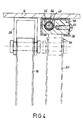
- FIGS. 3 and 4 illustrate a modified embodiment of a spring arrangement 36 which has a fastening fitting 38, the cross section of which corresponds approximately to the clear cross section of the rail 30 on the bottom side of the lifting plate 14 and which extends over a certain length within this rail 30.
- a straight rod 40 extends through the entire length of the fastening fitting 38 and passes through a bore 42 provided in the rear part of the fastening fitting 38 with sliding play.
- the bore 42 extends through a transverse wall of the fastening fitting 38, which is adjoined at the front by a channel-like opening 44 which is open at the top and which has a somewhat larger cross section than the bore 42.
- a cylindrical helical compression spring 46 is guided in a longitudinally displaceable manner on the rod 40, one end of which is supported on a nut screwed onto the rod 40, which forms a head 48 for the rod 40.
- the other end of the helical compression spring 46 rests on the front surface of the transverse wall having the bore 42.
- the helical compression spring 46 is installed with pretension so that a nut screwed onto the rear end of the rod 40 is supported on the rear surface of this transverse wall. This nut forms a foot 50 of the rod 40.
- the mounting bracket 38 is in the form of a plastic body which is screwed onto a side wall of the rail 30 by means of two screws 52.
- the inner swivel frame 20 pivots each of the two guide devices 16 in a clockwise direction upwards and the two sliding bearings 34 in the form of sliding pieces running in the rails 30 come into contact with the head 48 of the displaceable rod 40.
- the rod 40 is shifted to the left and the compression spring 46 is compressed.
- the force of the spring 46 is dimensioned such that the tendency of the sliding bearings 34 in the rails 30 to clamp due to the steep position of the swivel frames 18, 20 is overcome.
- the entire spring arrangement 36 then has approximately twice the length. Thanks to the significant length of the mounting bracket 38 within the rail 30, the compression spring 46 is positively guided, namely in that it is stabilized by the inner rod 40, which has a sliding guide in the bore 42 at the rear end, while the channel-like opening 44, the coil spring 46 leads directly to the front end of the mounting bracket 38.
Landscapes
- Health & Medical Sciences (AREA)
- Nursing (AREA)
- Life Sciences & Earth Sciences (AREA)
- Animal Behavior & Ethology (AREA)
- General Health & Medical Sciences (AREA)
- Public Health (AREA)
- Veterinary Medicine (AREA)
- Devices For Medical Bathing And Washing (AREA)
- Percussion Or Vibration Massage (AREA)
- Massaging Devices (AREA)
- Medicines Containing Plant Substances (AREA)
- Organic Low-Molecular-Weight Compounds And Preparation Thereof (AREA)
Priority Applications (1)
| Application Number | Priority Date | Filing Date | Title |
|---|---|---|---|
| AT88117429T ATE65904T1 (de) | 1987-12-19 | 1988-10-19 | Badewanneneinsatz. |
Applications Claiming Priority (2)
| Application Number | Priority Date | Filing Date | Title |
|---|---|---|---|
| DE3743193 | 1987-12-19 | ||
| DE19873743193 DE3743193A1 (de) | 1987-12-19 | 1987-12-19 | Badewanneneinsatz |
Publications (3)
| Publication Number | Publication Date |
|---|---|
| EP0324899A2 EP0324899A2 (de) | 1989-07-26 |
| EP0324899A3 EP0324899A3 (en) | 1989-11-02 |
| EP0324899B1 true EP0324899B1 (de) | 1991-08-07 |
Family
ID=6343037
Family Applications (1)
| Application Number | Title | Priority Date | Filing Date |
|---|---|---|---|
| EP88117429A Expired - Lifetime EP0324899B1 (de) | 1987-12-19 | 1988-10-19 | Badewanneneinsatz |
Country Status (6)
| Country | Link |
|---|---|
| EP (1) | EP0324899B1 (enExample) |
| JP (1) | JPH01170458A (enExample) |
| AT (1) | ATE65904T1 (enExample) |
| DE (2) | DE3743193A1 (enExample) |
| ES (1) | ES2023479B3 (enExample) |
| GR (1) | GR3002682T3 (enExample) |
Families Citing this family (8)
| Publication number | Priority date | Publication date | Assignee | Title |
|---|---|---|---|---|
| DE3931385A1 (de) * | 1989-09-20 | 1991-03-28 | Peter Heckmeier | Badewannenhebegeraet |
| WO1991015179A1 (de) * | 1990-04-11 | 1991-10-17 | Hans Fickler | Badelift |
| KR20000030608A (ko) * | 2000-03-08 | 2000-06-05 | 김종현 | 집진기용 분사노즐 |
| GB2474580B (en) * | 2009-10-19 | 2012-06-20 | Paul Martin Huband | An improved bath |
| CN101961214B (zh) * | 2010-11-03 | 2012-03-21 | 河南科技大学 | 个人卫生护理浴缸 |
| CN101966111B (zh) * | 2010-11-03 | 2012-06-13 | 河南科技大学 | 用于人体进出浴缸的人体转移装置 |
| CN109172190B (zh) * | 2018-09-25 | 2020-07-21 | 段长虹 | 一种瘫痪病人护理床 |
| KR20230154452A (ko) | 2021-03-09 | 2023-11-08 | 다이킨 고교 가부시키가이샤 | 용융성 불소 수지 프라이머 |
Family Cites Families (10)
| Publication number | Priority date | Publication date | Assignee | Title |
|---|---|---|---|---|
| FR712125A (fr) * | 1930-03-13 | 1931-09-25 | Tecalemit | Appareil de levage perfectionné, notamment pour véhicules automobiles |
| US3106723A (en) * | 1963-01-04 | 1963-10-15 | Theodore R Carpenter | Power elevatable bath tub seat |
| AU521977B2 (en) * | 1977-11-09 | 1982-05-13 | Wright, H.S. | Bathing or shower apparatus |
| DE8209606U1 (de) * | 1981-03-31 | 1984-10-11 | Schmidt, Peter, 7989 Argenbühl | Tragplatte eines Badewannen-Hubeinsatzes |
| DE3134513A1 (de) * | 1981-09-01 | 1983-03-17 | Peter 7989 Argenbühl Schmidt | "badewanneneinsatz" |
| JPS59174822U (ja) * | 1983-05-11 | 1984-11-22 | 株式会社佐藤鉄工所 | 昇降浴槽に装着した担架用台枠の昇降装置 |
| DE3324294A1 (de) * | 1983-07-06 | 1985-01-24 | Peter 7989 Argenbühl Schmidt | Badewanneneinsatz fuer behinderte |
| GB2156210B (en) * | 1984-03-29 | 1987-04-08 | John Alfred Hooker | Bath aid unit |
| JPH0133073Y2 (enExample) * | 1985-02-19 | 1989-10-06 | ||
| DE3508056A1 (de) * | 1985-03-07 | 1986-09-18 | Peter 7989 Eisenharz Schmidt | Badewanneneinsatz |
-
1987
- 1987-12-19 DE DE19873743193 patent/DE3743193A1/de not_active Withdrawn
-
1988
- 1988-10-19 DE DE8888117429T patent/DE3864138D1/de not_active Expired - Lifetime
- 1988-10-19 EP EP88117429A patent/EP0324899B1/de not_active Expired - Lifetime
- 1988-10-19 ES ES88117429T patent/ES2023479B3/es not_active Expired - Lifetime
- 1988-10-19 AT AT88117429T patent/ATE65904T1/de not_active IP Right Cessation
- 1988-11-18 JP JP63292255A patent/JPH01170458A/ja active Granted
-
1991
- 1991-09-10 GR GR91401293T patent/GR3002682T3/el unknown
Also Published As
| Publication number | Publication date |
|---|---|
| EP0324899A2 (de) | 1989-07-26 |
| DE3743193A1 (de) | 1989-06-29 |
| GR3002682T3 (en) | 1993-01-25 |
| JPH01170458A (ja) | 1989-07-05 |
| ES2023479B3 (es) | 1992-01-16 |
| DE3864138D1 (de) | 1991-09-12 |
| ATE65904T1 (de) | 1991-08-15 |
| EP0324899A3 (en) | 1989-11-02 |
| JPH0453546B2 (enExample) | 1992-08-26 |
Similar Documents
| Publication | Publication Date | Title |
|---|---|---|
| EP0589190B1 (de) | Armlehne für Sitzmöbel | |
| DE9406891U1 (de) | Klapp-Schwing-Dachfenster mit Ausstellhilfe | |
| DE102015102660A1 (de) | Tisch mit einer Tischplatte und einem Tischfuß, sowie in einem Reisemobil eingebauter Tisch | |
| DE3233569A1 (de) | Tisch-bett-kombinationsmoebel | |
| EP0324899B1 (de) | Badewanneneinsatz | |
| CH670555A5 (enExample) | ||
| DE4105528C2 (enExample) | ||
| DE20217975U1 (de) | Einzugsvorrichtung für Schubladen | |
| DE602004009547T2 (de) | Absperrschieber | |
| AT400795B (de) | Schublade | |
| DE69107734T2 (de) | Träger für eine Fahrzeughebevorrichtung. | |
| DE102005028573A1 (de) | Befestigungsanordnung für Möbelteile, insbesondere Tischmöbelteile | |
| DE29800097U1 (de) | Sicherungselement für Stützeinrichtungen an Fahrzeuganhängern | |
| DE4004158C2 (de) | Halteblock für Konsolen | |
| DE4204523A1 (de) | Abdeckvorrichtung fuer eine schiene eines fahrzeugsitzes, insbesondere eines kraftfahrzeugsitzes | |
| DE2821101A1 (de) | Moebel-auszugfuehrung | |
| AT402141B (de) | Arbeitspult, insbesondere schreibtisch | |
| DE202005009719U1 (de) | Befestigungsanordnung für Möbelteile, insbesondere Tischmöbelteile | |
| DE19800227C1 (de) | Sicherungselement für Stützeinrichtungen an Fahrzeuganhängern | |
| EP0916284A2 (de) | Höhenverstellbarer Arbeitstisch | |
| DE3325199C2 (enExample) | ||
| DE9207058U1 (de) | Fadenspannvorrichtung an einem Spulengatter | |
| DE1944023C3 (de) | Verstellbarer Gestellfuß mit einem beweglichen Fußstück für Schranke, Gestelle oder dergleichen | |
| DE10201105B4 (de) | Möbelbeschlag | |
| AT392767B (de) | Vorrichtung zur verlaengerung des mastes eines riggs fuer ein segelbrett oder segelboot |
Legal Events
| Date | Code | Title | Description |
|---|---|---|---|
| PUAI | Public reference made under article 153(3) epc to a published international application that has entered the european phase |
Free format text: ORIGINAL CODE: 0009012 |
|
| AK | Designated contracting states |
Kind code of ref document: A2 Designated state(s): AT BE CH DE ES FR GB GR IT LI LU NL SE |
|
| PUAL | Search report despatched |
Free format text: ORIGINAL CODE: 0009013 |
|
| AK | Designated contracting states |
Kind code of ref document: A3 Designated state(s): AT BE CH DE ES FR GB GR IT LI LU NL SE |
|
| 17P | Request for examination filed |
Effective date: 19890928 |
|
| 17Q | First examination report despatched |
Effective date: 19910125 |
|
| GRAA | (expected) grant |
Free format text: ORIGINAL CODE: 0009210 |
|
| AK | Designated contracting states |
Kind code of ref document: B1 Designated state(s): AT BE CH DE ES FR GB GR IT LI LU NL SE |
|
| REF | Corresponds to: |
Ref document number: 65904 Country of ref document: AT Date of ref document: 19910815 Kind code of ref document: T |
|
| REF | Corresponds to: |
Ref document number: 3864138 Country of ref document: DE Date of ref document: 19910912 |
|
| ET | Fr: translation filed | ||
| GBT | Gb: translation of ep patent filed (gb section 77(6)(a)/1977) | ||
| ITF | It: translation for a ep patent filed | ||
| REG | Reference to a national code |
Ref country code: GB Ref legal event code: 732 |
|
| ITPR | It: changes in ownership of a european patent |
Owner name: CESSIONE;SCHMIDT & LENHARDT GMBH & CO. OHG |
|
| REG | Reference to a national code |
Ref country code: CH Ref legal event code: PUE Owner name: SCHMIDT & LENHARDT GMBH & CO. OHG |
|
| NLS | Nl: assignments of ep-patents |
Owner name: SCHMIDT & LENHARDT GMBH & CO. OHG TE EISENHARZ, BO |
|
| PLBE | No opposition filed within time limit |
Free format text: ORIGINAL CODE: 0009261 |
|
| STAA | Information on the status of an ep patent application or granted ep patent |
Free format text: STATUS: NO OPPOSITION FILED WITHIN TIME LIMIT |
|
| REG | Reference to a national code |
Ref country code: FR Ref legal event code: TP |
|
| 26N | No opposition filed | ||
| REG | Reference to a national code |
Ref country code: GR Ref legal event code: FG4A Free format text: 3002682 |
|
| REG | Reference to a national code |
Ref country code: ES Ref legal event code: PC2A Owner name: SCHMIDT & LENHARDT GMBH & CO. OHG |
|
| EPTA | Lu: last paid annual fee | ||
| EAL | Se: european patent in force in sweden |
Ref document number: 88117429.6 |
|
| PGFP | Annual fee paid to national office [announced via postgrant information from national office to epo] |
Ref country code: GR Payment date: 19960930 Year of fee payment: 9 Ref country code: BE Payment date: 19960930 Year of fee payment: 9 |
|
| PGFP | Annual fee paid to national office [announced via postgrant information from national office to epo] |
Ref country code: LU Payment date: 19961001 Year of fee payment: 9 |
|
| PGFP | Annual fee paid to national office [announced via postgrant information from national office to epo] |
Ref country code: GB Payment date: 19961010 Year of fee payment: 9 |
|
| PG25 | Lapsed in a contracting state [announced via postgrant information from national office to epo] |
Ref country code: LU Free format text: LAPSE BECAUSE OF NON-PAYMENT OF DUE FEES Effective date: 19971019 Ref country code: GB Free format text: LAPSE BECAUSE OF NON-PAYMENT OF DUE FEES Effective date: 19971019 |
|
| PG25 | Lapsed in a contracting state [announced via postgrant information from national office to epo] |
Ref country code: GR Free format text: LAPSE BECAUSE OF NON-PAYMENT OF DUE FEES Effective date: 19971031 Ref country code: BE Free format text: LAPSE BECAUSE OF NON-PAYMENT OF DUE FEES Effective date: 19971031 |
|
| BERE | Be: lapsed |
Owner name: SCHMIDT & LENHARDT G.M.B.H. & CO. OHG. Effective date: 19971031 |
|
| GBPC | Gb: european patent ceased through non-payment of renewal fee |
Effective date: 19971019 |
|
| PGFP | Annual fee paid to national office [announced via postgrant information from national office to epo] |
Ref country code: CH Payment date: 19980824 Year of fee payment: 11 |
|
| PGFP | Annual fee paid to national office [announced via postgrant information from national office to epo] |
Ref country code: AT Payment date: 19980825 Year of fee payment: 11 |
|
| PGFP | Annual fee paid to national office [announced via postgrant information from national office to epo] |
Ref country code: FR Payment date: 19980917 Year of fee payment: 11 |
|
| PGFP | Annual fee paid to national office [announced via postgrant information from national office to epo] |
Ref country code: ES Payment date: 19981020 Year of fee payment: 11 |
|
| PGFP | Annual fee paid to national office [announced via postgrant information from national office to epo] |
Ref country code: SE Payment date: 19981022 Year of fee payment: 11 |
|
| PGFP | Annual fee paid to national office [announced via postgrant information from national office to epo] |
Ref country code: NL Payment date: 19981026 Year of fee payment: 11 |
|
| PG25 | Lapsed in a contracting state [announced via postgrant information from national office to epo] |
Ref country code: AT Free format text: LAPSE BECAUSE OF NON-PAYMENT OF DUE FEES Effective date: 19991019 |
|
| PG25 | Lapsed in a contracting state [announced via postgrant information from national office to epo] |
Ref country code: ES Free format text: LAPSE BECAUSE OF NON-PAYMENT OF DUE FEES Effective date: 19991020 |
|
| PG25 | Lapsed in a contracting state [announced via postgrant information from national office to epo] |
Ref country code: SE Free format text: THE PATENT HAS BEEN ANNULLED BY A DECISION OF A NATIONAL AUTHORITY Effective date: 19991030 |
|
| PG25 | Lapsed in a contracting state [announced via postgrant information from national office to epo] |
Ref country code: LI Free format text: LAPSE BECAUSE OF NON-PAYMENT OF DUE FEES Effective date: 19991031 Ref country code: CH Free format text: LAPSE BECAUSE OF NON-PAYMENT OF DUE FEES Effective date: 19991031 |
|
| PG25 | Lapsed in a contracting state [announced via postgrant information from national office to epo] |
Ref country code: NL Free format text: LAPSE BECAUSE OF NON-PAYMENT OF DUE FEES Effective date: 20000501 |
|
| REG | Reference to a national code |
Ref country code: CH Ref legal event code: PL |
|
| EUG | Se: european patent has lapsed |
Ref document number: 88117429.6 |
|
| PG25 | Lapsed in a contracting state [announced via postgrant information from national office to epo] |
Ref country code: FR Free format text: LAPSE BECAUSE OF NON-PAYMENT OF DUE FEES Effective date: 20000630 |
|
| NLV4 | Nl: lapsed or anulled due to non-payment of the annual fee |
Effective date: 20000501 |
|
| REG | Reference to a national code |
Ref country code: FR Ref legal event code: ST |
|
| PGFP | Annual fee paid to national office [announced via postgrant information from national office to epo] |
Ref country code: DE Payment date: 20001214 Year of fee payment: 13 |
|
| PG25 | Lapsed in a contracting state [announced via postgrant information from national office to epo] |
Ref country code: DE Free format text: LAPSE BECAUSE OF NON-PAYMENT OF DUE FEES Effective date: 20020702 |
|
| REG | Reference to a national code |
Ref country code: ES Ref legal event code: FD2A Effective date: 20001113 |
|
| PG25 | Lapsed in a contracting state [announced via postgrant information from national office to epo] |
Ref country code: IT Free format text: LAPSE BECAUSE OF NON-PAYMENT OF DUE FEES;WARNING: LAPSES OF ITALIAN PATENTS WITH EFFECTIVE DATE BEFORE 2007 MAY HAVE OCCURRED AT ANY TIME BEFORE 2007. THE CORRECT EFFECTIVE DATE MAY BE DIFFERENT FROM THE ONE RECORDED. Effective date: 20051019 |