EP0324384B1 - Tensioning device for cable traction drives - Google Patents
Tensioning device for cable traction drives Download PDFInfo
- Publication number
- EP0324384B1 EP0324384B1 EP89100186A EP89100186A EP0324384B1 EP 0324384 B1 EP0324384 B1 EP 0324384B1 EP 89100186 A EP89100186 A EP 89100186A EP 89100186 A EP89100186 A EP 89100186A EP 0324384 B1 EP0324384 B1 EP 0324384B1
- Authority
- EP
- European Patent Office
- Prior art keywords
- drive
- rope
- cable
- cable traction
- tensioning device
- Prior art date
- Legal status (The legal status is an assumption and is not a legal conclusion. Google has not performed a legal analysis and makes no representation as to the accuracy of the status listed.)
- Expired - Lifetime
Links
- 238000005065 mining Methods 0.000 claims description 2
- 230000036316 preload Effects 0.000 description 2
- 230000007704 transition Effects 0.000 description 1
Images

Classifications
-
- B—PERFORMING OPERATIONS; TRANSPORTING
- B61—RAILWAYS
- B61B—RAILWAY SYSTEMS; EQUIPMENT THEREFOR NOT OTHERWISE PROVIDED FOR
- B61B12/00—Component parts, details or accessories not provided for in groups B61B7/00 - B61B11/00
- B61B12/007—Cable tensioning devices
-
- B—PERFORMING OPERATIONS; TRANSPORTING
- B61—RAILWAYS
- B61B—RAILWAY SYSTEMS; EQUIPMENT THEREFOR NOT OTHERWISE PROVIDED FOR
- B61B12/00—Component parts, details or accessories not provided for in groups B61B7/00 - B61B11/00
- B61B12/10—Cable traction drives
Definitions
- the invention relates to a cable car machine, in particular for mining, with a traction sheave, which is at the same time displaceable as a tensioning device for the rope by an actuator, the force of which is controlled as a function of the torque of the traction sheave.
- Such a cable car machine is known from DE-OS 25 09 059.
- the document makes the proposal, in a cable car machine with two traction sheaves around which the rope is guided in an S-shape, to make one traction sheave no longer simply a tensioning device relative to the other, fixedly mounted traction sheave, but rather the tension force with the torque of the traction sheaves to change.
- the torque depends on the size of the load and the slope at the point on the path where the load is currently located. It is converted into the tensile force of the rope on the rope sheave. The tensile force of the rope must be held on the traction sheave by friction. This is proportional to the clamping force.
- the clamping force can only be kept as high as necessary. This protects the rope in comparison too tight preload, which has to be measured according to the greatest load and is therefore unnecessarily high in most load conditions.
- the proposal fails when a load pulls downhill and braking force has to be applied. Then the actuator should be locked in order to generate a fixed preload as before. This cable car machine could not be introduced.
- the invention has for its object to provide a cable car machine with a tensioning device that adapts to all load conditions.
- the solution consists in a cable car machine of the type described in the introduction, which has only one traction sheave or in which all traction sheaves together form the tensioning device.
- the torque or a variable proportional to it can be in various ways on the rotary drive of the traction sheave or drive slices are tapped.
- the rotary drive of the traction sheave or traction sheaves has a planetary gear, the outer ring of which is rotatably arranged and drive means for the traction drive with an external toothing.
- a support frame 2 on rollers 3 is displaceable, which carries two traction sheaves 6 and 7 in two blocks 4 and 5.
- an endless cable 9 of a cable car is placed, ie an industrial conveyor, between the rails of which one strand of the cable 9, referred to as a cable 10, is guided and takes a train wagon attached to it, while the other strand, referred to as return rope 11, runs underneath or next to the cable car machine from a reverser arranged at the other end of the track.
- a rotary drive 12 for the traction sheaves 6 and 7 has a pump 15 driven by an electric motor 13 via a clutch 14, a hydraulic line 17 leading from the latter to a hydraulic motor 16 and back, and a clutch 18 via which the traction sheaves 6 and 7 are connected approximately the same torque is transmitted.
- a branch line 19 leads from the hydraulic line 17 to a converter 20, from which a lifting cylinder 22 is acted on via a line 21. This is fixed on the one hand at 23 to the base plate 1 and on the other hand engages with its piston rod 24 at 25 on the support frame 2.
- the loading of the lifting cylinder 22 by the converter 20 is proportional to the pressure in the hydraulic line 17 such that the train on the support frame 2 and thus on the rope runs of the railway rope 10 and return rope 11 is always only slightly larger than necessary to prevent the traction sheaves 6 from slipping and 7 to prevent the rope.
- the function of the cable machine as a tensioning device in addition to the function as a drive device can be seen without further explanation: by pulling the lifting cylinder 22 on the support frame 2, the traction sheaves 6 and 7, with the aid of the deflecting rollers 8, tension the rope on its two rope strands, the railway rope 10 and return rope 11.
- they In order to always move the majority of traction sheaves simultaneously in the tensioning direction of the two rope runs, they are moved in the Usually arrange them in a rigid connection of their bearings.
- a support frame 27 on rollers 28 can be displaced on a substructure 26 by means of a chain hoist 29 arranged in the substructure, to which the support frame 27 is connected by a driver 30.
- a bracket 31 with a traction sheave 32 for a rope 33 is arranged on the support frame 27.
- a geared motor 34 engages on the shaft of the traction sheave 32, which is supported on the support frame 27 only via a torque support 35.
- a controller 36 is connected to a dynamometer 37 in the torque arm 35 and a dynamometer 38 in the chain hoist 29 and controls a drive sprocket 39 of the chain hoist 29 in proportion to the size indicated by the dynamometer 37 so that the chain hoist 29 over the support frame 27 and the Traction sheave 32 gives the rope 33 not much more than the required pretension.
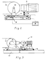
- FIG. 3 shows, corresponding to FIGS. 1 and 2, a base plate 40, a support frame 41 with rollers 42, a trestle 43, a traction sheave 44 for a rope 45 and a drive 46.
- the drive 46 comprises a planetary gear 47 with a second output shaft 48 which is driven by the otherwise stationary outer ring or ring gear of the planetary gear.
- the second output shaft 48 acts on a pinion 49, consisting of a toothed rack 50 rigidly connected to the base plate 40 and a pinion 51 arranged in the support frame 41.
- the torque acting in the outer ring or ring gear of a planetary gear is proportional to the torque output by the planetary gear.
- the tensile force generated in the pinion 49 and tensioning the cable 45 is therefore proportional to the torque delivered to the drive pulley 44.
- the gear ratios including the The diameter of the pinion 51 are dimensioned such that the tensile force is somewhat greater than the required rope tension.
- the rope tension may exceed the minimum value by 5 to 10%.
- the ropeway machines with only one traction sheave could also have, in a known manner, at least one deflection roller, by means of which the rope is laid several times over the traction sheave.
- the deflection roller (s) will then be moved together with the traction sheave, preferably in rigid connection with it, in the direction of the sapnn and back.
Landscapes
- Engineering & Computer Science (AREA)
- Transportation (AREA)
- Mechanical Engineering (AREA)
- Transmission Devices (AREA)
- Devices For Conveying Motion By Means Of Endless Flexible Members (AREA)
Description
Die Erfindung betrifft eine Seilbahnmaschine, insbesondere für den Bergbau, mit einer Treibscheibe, die zugleich als Spannvorrichtung für das Seil verschiebbar ist durch einen Stelltrieb, dessen Kraft abhängig vom Drehmoment der Treibscheibe gesteuert ist.The invention relates to a cable car machine, in particular for mining, with a traction sheave, which is at the same time displaceable as a tensioning device for the rope by an actuator, the force of which is controlled as a function of the torque of the traction sheave.
Eine solche Seilbahnmaschine ist aus der DE-OS 25 09 059 bekannt.
Die Schrift bringt den Vorschlag, in einer Seilbahnmaschine mit zwei Treibscheiben, um die das Seil S-förmig geführt ist, die eine Treibscheibe nicht mehr schlechthin als Spannvorrichtung verschiebbar zu machen gegenüber der anderen, feststehend gelagerten Treibscheibe, sondern die Spannkraft mit dem Drehmoment der Treibscheiben zu ändern.Such a cable car machine is known from DE-OS 25 09 059.
The document makes the proposal, in a cable car machine with two traction sheaves around which the rope is guided in an S-shape, to make one traction sheave no longer simply a tensioning device relative to the other, fixedly mounted traction sheave, but rather the tension force with the torque of the traction sheaves to change.
Das Drehmoment ist jeweils abhängig von der Größe der Last und der Steigung an derjenigen Stelle des Bahnverlaufs, wo sich die Last gerade befindet. Es wird an der Seilscheibe in die Zugkraft des Seiles umgesetzt. Die Zugkraft des Seiles muß an der Treibscheibe durch Reibungskraft gehalten werden. Diese ist proportional der Spannkraft.The torque depends on the size of the load and the slope at the point on the path where the load is currently located. It is converted into the tensile force of the rope on the rope sheave. The tensile force of the rope must be held on the traction sheave by friction. This is proportional to the clamping force.
Mit der Steuerung kann die Spannkraft immer gerade nur so groß wie nötig gehalten werden. Damit wird das Seil geschont im Vergleich zu fester Vorspannung, die sich nach dem größten Belastungsfall bemessen muß und daher in den meisten Belastungszuständen ganz unnötig hoch liegt.
Der Vorschlag versagt jedoch, wenn eine Last bergab zieht und Bremskraft ausgeübt werden muß. Dann soll der Stelltrieb jeweils verriegelt werden, um eine feste Vorspannung wie vordem zu erzeugen.
Diese Seilbahnmaschine konnte sich nicht einführen.With the control, the clamping force can only be kept as high as necessary. This protects the rope in comparison too tight preload, which has to be measured according to the greatest load and is therefore unnecessarily high in most load conditions.
However, the proposal fails when a load pulls downhill and braking force has to be applied. Then the actuator should be locked in order to generate a fixed preload as before.
This cable car machine could not be introduced.
Der Erfindung liegt die Aufgabe zugrunde, eine Seilbahnmaschine mit einer Spannvorrichtung zu schaffen, die sich allen Belastungszuständen anpaßt.The invention has for its object to provide a cable car machine with a tensioning device that adapts to all load conditions.
Gemäß der Erfindung besteht die Lösung in einer Seilbahnmaschine der eingangs bezeichneten Art, die nur eine Treibscheibe aufweist oder bei der alle Treibscheiben zusammen die Spannvorrichtung bilden.According to the invention, the solution consists in a cable car machine of the type described in the introduction, which has only one traction sheave or in which all traction sheaves together form the tensioning device.
Berechnet man für die vier möglichen Belastungsfälle 1) Lauf des Bahnseils zur Seilbahnmaschine a) bergauf, b) bergab (Bremsen), 2) Lauf des Bahnseils zur Umkehre a) bergauf, b) bergab (Bremsen) die erforderliche Spannkraft ausgehend von den Zugkräften des Bahnseils, des Rückführseils und ggf. des Seilabschnittes zwischen zwei Treibscheiben und von der an diesen jeweils benötigten Reibungskraft, so ergibt sich für die bekannte Vorrichtung beim Übergang von Ziehen auf Bremsen eine Änderung der benötigten Spannkraft im Verhältnis zur Zugkraft, worauf dort mit der erwähnten Verriegelung reagiert werden soll, für die erfindungsgemäße Vorrichtung aber zwar ebenfalls Umkehrung der Zugkraft, jedoch gleichbleibende Abhängigkeit der benötigten Spannkraft vom, nun bremsenden, Drehmoment der Treibscheiben.For the four possible load cases, 1) run the cable to the cable car machine a) uphill, b) downhill (brakes), 2) run the cable to reverse a) uphill, b) downhill (brakes) the required tension based on the tensile forces of the Railway rope, the return rope and, if necessary, the rope section between two traction sheaves and the frictional force required on them, this results in a change in the required tensioning force in relation to the tensile force for the known device during the transition from pulling to braking, whereupon with the mentioned locking should be reacted, but for the device according to the invention also reversal of the tensile force, but constant dependence of the required clamping force on the now braking torque of the traction sheaves.
Es ist also eine durchweg gleiche Automatik der Spannungssteuerung möglich.It is therefore possible to have the same automatic control of the voltage control.
Das Drehmoment bzw. eine dazu proportionale Größe kann auf verschiedene Weise an dem Drehantrieb der Treibscheibe bzw. Treib scheiben abgegriffen werden.The torque or a variable proportional to it can be in various ways on the rotary drive of the traction sheave or drive slices are tapped.
Bekannt ist aus der erwähnten DE-OS 25 09 059 bei einem hydraulischen Drehantrieb die Verwendung des hydraulischen Druckes.It is known from the aforementioned DE-OS 25 09 059 in a hydraulic rotary drive to use the hydraulic pressure.
Für die als eine Variante der vorliegenden Erfindung vorgesehene einzige Treibscheibe wird als weitere Ausgestaltung vorgeschlagen, daß ihr Drehantrieb über eine Drehmomentstütze gelagert und in dieser ein Kraftmeßgerät als Eingangsgrößengeber für die Steuerung des Stelltriebs der Spannvorrichtung angeordnet ist.For the single traction sheave provided as a variant of the present invention, it is proposed as a further embodiment that its rotary drive is mounted via a torque arm and in this a force measuring device is arranged as an input variable for controlling the actuator of the tensioning device.
Nach einer anderen, für beide Varianten einsetzbaren Ausgestaltung weist der Drehantrieb der Treibscheibe bzw. Treibscheiben ein Planetengetriebe auf, dessen Außenring drehbar angeordnet und mit einer äußeren Zahnung Antriebsmittel für den Zugantrieb ist.According to another embodiment that can be used for both variants, the rotary drive of the traction sheave or traction sheaves has a planetary gear, the outer ring of which is rotatably arranged and drive means for the traction drive with an external toothing.
Die Zeichnungen geben aus Ausführungsbeispiele der Erfindung wieder.
- Fig. 1 zeigt eine Seilbahnmaschine mit zwei Treibscheiben und einem hydraulischen Stelltrieb,
- Fig. 2 zeigt eine Seilbahnmaschine mit einer Treibscheibe und einem mechanischen, gesteuerten Stelltrieb und
- Fig. 3 zeigt eine Seilbahnmaschine mit einer Treibscheibe und einem rein mechanischen Stelltrieb.
- 1 shows a cable car machine with two traction sheaves and a hydraulic actuator,
- Fig. 2 shows a cable car machine with a traction sheave and a mechanical, controlled actuator and
- Fig. 3 shows a cable car machine with a traction sheave and a purely mechanical actuator.
Auf einer Grundplatte 1 ist ein Tragrahmen 2 auf Rollen 3 verschiebbar, der in zwei Böcken 4 und 5 zwei Treibscheiben 6 und 7 trägt.On a
S-förmig um die Treibscheiben 6 und 7 sowie um zwei Umlenkrollen 8 ist ein endloses Seil 9 einer Seilbahn gelegt, d.h. einer Flurförderbahn, zwischen deren Schienen in der Mitte der eine, als Bahnseil 10 bezeichnete Trum des Seiles 9 geführt ist und einen an ihm befestigten Zugwagen mitnimmt, während der andere, als Rückführseil 11 bezeichnete Trum darunter oder daneben von einer am anderen Ende der Bahn eingerichteten Umkehre aus zu der Seilbahnmaschine zurückläuft.S-shaped around the traction sheaves 6 and 7 as well as around two deflecting rollers 8, an endless cable 9 of a cable car is placed, ie an industrial conveyor, between the rails of which one strand of the cable 9, referred to as a
Ein Drehantrieb 12 für die Treibscheiben 6 und 7 weist eine von einem Elektromotor 13 über eine Kupplung 14 angetriebene Pumpe 15, eine von dieser zu einem Hydraulikmotor 16 und zurück führende Hydraulikleitung 17 sowie eine Kupplung 18 auf, über die an die Treibscheiben 6 und 7 ein etwa gleiches Drehmoment übertragen wird.A
Von der Hydraulikleitung 17 führt eine Zweigleitung 19 zu einem Umsetzer 20, von dem aus über eine Leitung 21 ein Hubzylinder 22 beaufschlagt ist. Dieser ist einerseits bei 23 an der Grundplatte 1 befestigt und greift andererseits mit seiner Kolbenstange 24 bei 25 an dem Tragrahmen 2 an.A
Die Beaufschlagung des Hubzylinders 22 durch den Umsetzer 20 ist proportional zum Druck in der Hydraulikleitung 17 derart, daß der Zug auf dem Tragrahmen 2 und damit an den Seiltrumen Bahnseil 10 und Rückführseil 11 immer nur wenig größer ist als erforderlich, um ein Rutschen der Treibscheiben 6 und 7 an dem Seil zu verhindern.
Die Funktion der Seilmaschine als Spannvorrichtung zusätzlich zu der Funktion als Antriebsvorrichtung ist ohne weitere Erläuterung ersichtlich: Durch den Zug des Hubzylinders 22 an dem Tragrahmen 2 spannen die Treibscheiben 6 und 7 zusammen, mit Hilfe der Umlenkrollen 8, das Seil an seinen beiden Seiltrumen Bahnseil 10 und Rückführseil 11.
Gleiches wäre mit drei oder mehr Treibscheiben auf dem Tragrahmen 2 möglich mit Umlenkrollen, soweit es die Richtungsverhältnisse erfordern.
Um die Mehrzahl von Treibscheiben immer gleichzeitig in Spannrichtung der beiden Seiltrume zu bewegen, wird man sie in der Regel in starrer Verbindung ihrer Lager miteinander anordnen.The loading of the
The function of the cable machine as a tensioning device in addition to the function as a drive device can be seen without further explanation: by pulling the
The same would be possible with three or more traction sheaves on the
In order to always move the majority of traction sheaves simultaneously in the tensioning direction of the two rope runs, they are moved in the Usually arrange them in a rigid connection of their bearings.
Nach Fig. 2 ist auf einer Unterkonstruktion 26 ein Tragrahmen 27 auf Rollen 28 mittels eines in der Unterkonstruktion angeordneten Kettenzuges 29 verschiebbar, mit dem der Tragrahmen 27 durch einen Mitnehmer 30 verbunden ist.According to FIG. 2, a
Auf dem Tragrahmen 27 ist ein Bock 31 mit einer Treibscheibe 32 für ein Seil 33 angeordnet.A
An der Welle der Treibscheibe 32 greift ein Getriebemotor 34 an, der im übrigen nur über eine Drehmomentstütze 35 auf dem Tragrahmen 27 abgestützt ist.A geared
Ein Steuergerät 36 ist mit einem Kraftmesser 37 in der Drehmomentstütze 35 und einem Kraftmesser 38 in dem Kettenzug 29 verbunden und steuert ein Antriebskettenrad 39 des Kettenzuges 29 proportional zu der von dem Kraftmesser 37 angezeigten Größe so, daß der Kettenzug 29 über den Tragrahmen 27 und die Treibscheibe 32 dem Seil 33 jeweils nicht viel mehr als die benötigte Vorspannung gibt.A
Fig. 3 zeigt entsprechend zu Fig. 1 und 2 eine Grundplatte 40, einen Tragrahmen 41 mit Rollen 42, einen Bock 43, eine Treibscheibe 44 für ein Seil 45 und einen Antrieb 46.3 shows, corresponding to FIGS. 1 and 2, a
Der Antrieb 46 umfaßt ein Planetengetriebe 47 mit einer zweiten Abtriebswelle 48, die von dem sonst gewöhnlich ruhenden Außenring oder Hohlrad des Planetengetriebes angetrieben ist. Die zweite Abtriebswelle 48 wirkt auf einen Zahntrieb 49, bestehend aus einer starr mit der Grundplatte 40 verbundenen Zahnstange 50 und einem in dem Tragrahmen 41 angeordneten Ritzel 51.The
Das im Außenring bzw. Hohlrad eines Planetengetriebes wirkende Drehmoment ist dem von dem Planetengetriebe abgegebenen Drehmoment proportional. Bei der vorgesehenen Anordnung ist demzufolge die in dem Zahntrieb 49 erzeugte, das Seil 45 spannende Zugkraft proportional zu dem an die Treibscheibe 44 abgegebenen Drehmoment. Die Übersetzungsverhältnisse einschließlich des Durchmessers des Ritzels 51 sind so bemessen, daß die Zugkraft etwas größer als die benötigte Seilspannung ist.The torque acting in the outer ring or ring gear of a planetary gear is proportional to the torque output by the planetary gear. In the arrangement provided, the tensile force generated in the
In allen drei beschriebenen Fällen mag die ausgeübte Seilspannung den Mindestwert um 5 bis 10% übersteigen.In all three cases described, the rope tension may exceed the minimum value by 5 to 10%.
Die Seilbahnmaschinen mit nur einer Treibscheibe könnten auch in bekannter Weise mindestens eine Umlenkrolle aufweisen, mittels derer das Seil mehrfach über die Treibscheibe gelegt wird. Die Umlenkrolle(n) wird man dann zusammen mit der Treibscheibe, vorzugsweise in starrer Verbindung mit ihr, in der Sapnnrichtung und zurück bewegen.The ropeway machines with only one traction sheave could also have, in a known manner, at least one deflection roller, by means of which the rope is laid several times over the traction sheave. The deflection roller (s) will then be moved together with the traction sheave, preferably in rigid connection with it, in the direction of the sapnn and back.
Claims (3)
characterised in that
the cable traction drive has only one driving pulley (32; 44) or all its driving pulleys (6, 7) together form the tensioning device.
characterised in that
the rotary drive (34) for the single driving pulley (32) is supported via a torque converter bearing (35) and a force-sensing device (37) is disposed therein as an input value transmitter for the control unit (36) of the adjusting drive (29).
characterised in that
the rotary drive for the driving pulley (44) or driving pulleys has an epicyclic gear (47) whose outer ring is rotatable and together with an external toothing constitutes driving means for the tensioning drive (49).
Applications Claiming Priority (2)
| Application Number | Priority Date | Filing Date | Title |
|---|---|---|---|
| DE3800689 | 1988-01-13 | ||
| DE3800689A DE3800689A1 (en) | 1988-01-13 | 1988-01-13 | ROPE MACHINE, ESPECIALLY FOR MINING |
Publications (3)
| Publication Number | Publication Date |
|---|---|
| EP0324384A2 EP0324384A2 (en) | 1989-07-19 |
| EP0324384A3 EP0324384A3 (en) | 1989-09-27 |
| EP0324384B1 true EP0324384B1 (en) | 1992-05-06 |
Family
ID=6345148
Family Applications (1)
| Application Number | Title | Priority Date | Filing Date |
|---|---|---|---|
| EP89100186A Expired - Lifetime EP0324384B1 (en) | 1988-01-13 | 1989-01-07 | Tensioning device for cable traction drives |
Country Status (2)
| Country | Link |
|---|---|
| EP (1) | EP0324384B1 (en) |
| DE (2) | DE3800689A1 (en) |
Families Citing this family (7)
| Publication number | Priority date | Publication date | Assignee | Title |
|---|---|---|---|---|
| FR2665131B1 (en) * | 1990-07-27 | 1995-01-13 | Reel Sa | CABLE TRANSFER INSTALLATION COMPRISING MEANS FOR CONTROLLING THE TENSION AND THE ADHESION OF THE TRACTOR CABLE ON THE DRIVE PULLEY. |
| FR2695897B1 (en) * | 1992-09-18 | 1994-11-18 | Reel Sa | Cable transport installation. |
| AT405733B (en) * | 1997-07-16 | 1999-11-25 | Girak Garaventa Gmbh | Funicular railway |
| AT2306U1 (en) * | 1997-07-16 | 1998-08-25 | Girak Garaventa Gmbh | Funicular |
| IT1313913B1 (en) * | 1999-10-01 | 2002-09-26 | Leitner Spa | URBAN GUIDED TRANSPORT SYSTEM. |
| FR2958988B1 (en) * | 2010-04-16 | 2012-05-18 | Pomagalski Sa | METHOD AND INSTALLATION FOR POWERING A CABLE |
| CN112225021B (en) * | 2020-11-02 | 2022-04-12 | 江苏蒙哥马利电梯有限公司 | Intelligent elevator dispatching control method based on planetary gear transmission module |
Family Cites Families (5)
| Publication number | Priority date | Publication date | Assignee | Title |
|---|---|---|---|---|
| FR1578917A (en) * | 1968-05-06 | 1969-08-22 | ||
| FR1589145A (en) * | 1968-09-12 | 1970-03-23 | ||
| DE2509059A1 (en) * | 1975-03-01 | 1976-09-02 | Gewerk Eisenhuette Westfalia | CLAMPING CABLEWAY MACHINE |
| US4470355A (en) * | 1977-11-14 | 1984-09-11 | Kunczynski Jan K | Pneumatic cable tensioning apparatus and method for an aerial tramway or the like |
| AT367692B (en) * | 1981-01-28 | 1982-07-26 | Josef Dipl Ing Dr Techn Nejez | TENSIONING DEVICE FOR CONVEYOR ROPES OF CABLE CARS AND TOW LIFTS |
-
1988
- 1988-01-13 DE DE3800689A patent/DE3800689A1/en not_active Withdrawn
-
1989
- 1989-01-07 DE DE8989100186T patent/DE58901290D1/en not_active Expired - Lifetime
- 1989-01-07 EP EP89100186A patent/EP0324384B1/en not_active Expired - Lifetime
Also Published As
| Publication number | Publication date |
|---|---|
| EP0324384A3 (en) | 1989-09-27 |
| DE3800689A1 (en) | 1989-07-27 |
| DE58901290D1 (en) | 1992-06-11 |
| EP0324384A2 (en) | 1989-07-19 |
Similar Documents
| Publication | Publication Date | Title |
|---|---|---|
| DE2208694C2 (en) | Clamping device for the handrail drive on escalators and passenger conveyor belts | |
| EP0324384B1 (en) | Tensioning device for cable traction drives | |
| DE2629279C3 (en) | Infinitely variable V-belt drive | |
| DE3146092C2 (en) | ||
| DE2937293A1 (en) | ROPE PRESSURE DEVICE FOR ROPE DISCS | |
| EP0142537A1 (en) | Installation for displacing aircrafts. | |
| DE2813063C2 (en) | ||
| DE3511655A1 (en) | Device for the uniform lifting and lowering of an elongated load | |
| EP0677480B1 (en) | Compact cable traction device | |
| DE1535154C3 (en) | Device for regulating a winding drive | |
| DE2518753B2 (en) | Two-room shaft hoisting machine, in particular decoiler and further reel | |
| EP1439145A1 (en) | Elevator with separate car suspension | |
| DE3116715A1 (en) | Apparatus for installing a rope in shaft winding plant and the like | |
| DE20302373U1 (en) | Scissor lift mechanism for table or bench has a top frame and a bottom frame linked by diagonal scissor members linked by a common axle where the lifting action is effected by a motor with winding shaft and cable link | |
| DE3417861A1 (en) | Guide frame for sliding roofs of motor vehicles or tiltable sliding roofs | |
| EP0538237B1 (en) | Drive for double drum | |
| AT402062B (en) | Dual-drum drive | |
| DE2818411A1 (en) | Drive for continuous stretching of strip or wire - uses rollers driven via speed and torque compensation bevel drives from single power source | |
| EP1574472A2 (en) | Elevator system with driving gear incorporated in the counterweight | |
| DE217642C (en) | ||
| DE405003C (en) | Mechanical remote control for winches with the help of a single pulling element | |
| DE9013918U1 (en) | Hoist | |
| DE2020858A1 (en) | Drive for escalators | |
| DE4330162A1 (en) | Cable tackle line with drive disc and automatic cable compression - has drive disc in longitudinally slidable frame, displaceable in fixed frame. | |
| DE2362726C3 (en) | Reel with grooved pulley, especially for rope-operated transport systems in mining |
Legal Events
| Date | Code | Title | Description |
|---|---|---|---|
| PUAI | Public reference made under article 153(3) epc to a published international application that has entered the european phase |
Free format text: ORIGINAL CODE: 0009012 |
|
| AK | Designated contracting states |
Kind code of ref document: A2 Designated state(s): DE FR GB |
|
| PUAL | Search report despatched |
Free format text: ORIGINAL CODE: 0009013 |
|
| AK | Designated contracting states |
Kind code of ref document: A3 Designated state(s): DE FR GB |
|
| 17P | Request for examination filed |
Effective date: 19891209 |
|
| 17Q | First examination report despatched |
Effective date: 19901001 |
|
| GRAA | (expected) grant |
Free format text: ORIGINAL CODE: 0009210 |
|
| AK | Designated contracting states |
Kind code of ref document: B1 Designated state(s): DE FR GB |
|
| PG25 | Lapsed in a contracting state [announced via postgrant information from national office to epo] |
Ref country code: GB Effective date: 19920506 Ref country code: FR Effective date: 19920506 |
|
| REF | Corresponds to: |
Ref document number: 58901290 Country of ref document: DE Date of ref document: 19920611 |
|
| EN | Fr: translation not filed | ||
| GBV | Gb: ep patent (uk) treated as always having been void in accordance with gb section 77(7)/1977 [no translation filed] | ||
| PGFP | Annual fee paid to national office [announced via postgrant information from national office to epo] |
Ref country code: DE Payment date: 19930113 Year of fee payment: 5 |
|
| PLBE | No opposition filed within time limit |
Free format text: ORIGINAL CODE: 0009261 |
|
| STAA | Information on the status of an ep patent application or granted ep patent |
Free format text: STATUS: NO OPPOSITION FILED WITHIN TIME LIMIT |
|
| 26N | No opposition filed | ||
| PG25 | Lapsed in a contracting state [announced via postgrant information from national office to epo] |
Ref country code: DE Effective date: 19941001 |