EP1574472A2 - Elevator system with driving gear incorporated in the counterweight - Google Patents
Elevator system with driving gear incorporated in the counterweight Download PDFInfo
- Publication number
- EP1574472A2 EP1574472A2 EP05004505A EP05004505A EP1574472A2 EP 1574472 A2 EP1574472 A2 EP 1574472A2 EP 05004505 A EP05004505 A EP 05004505A EP 05004505 A EP05004505 A EP 05004505A EP 1574472 A2 EP1574472 A2 EP 1574472A2
- Authority
- EP
- European Patent Office
- Prior art keywords
- drive
- counterweight
- roller
- elevator
- support means
- Prior art date
- Legal status (The legal status is an assumption and is not a legal conclusion. Google has not performed a legal analysis and makes no representation as to the accuracy of the status listed.)
- Granted
Links
Images


Classifications
-
- B—PERFORMING OPERATIONS; TRANSPORTING
- B66—HOISTING; LIFTING; HAULING
- B66B—ELEVATORS; ESCALATORS OR MOVING WALKWAYS
- B66B11/00—Main component parts of lifts in, or associated with, buildings or other structures
- B66B11/0035—Arrangement of driving gear, e.g. location or support
- B66B11/0045—Arrangement of driving gear, e.g. location or support in the hoistway
- B66B11/0055—Arrangement of driving gear, e.g. location or support in the hoistway on the counterweight
Definitions
- the invention relates to an elevator installation with an elevator car and at least a drive unit and a balance weight with counterweight, wherein the Elevator car and the balance weight by means of at least one support means are interconnected, and the at least one support means to at least one rotating disc or roller is deflected.
- the drive regardless of the type of drive, either arranged in a separate engine room or it is a so-called machine room-less elevator, in which the drive in the shaft immovable, is arranged on the elevator car or counterweight.
- the Counterweighting has several disadvantages, e.g. that a special one Design of the drive is required and that the space above the drive in the Counterweight can not be used for the installation of weights and that Counterweight therefore must have correspondingly larger dimensions.
- the suspension elements may be suspension cables, chains, belts or the like act.
- the rotating disk can be made of a traction sheave, a sprocket, a Pulley or the like may be formed.
- the invention has the object, a To provide elevator installation of the type mentioned, in which the material requirement for the balance weight is reduced, the dimensions are as small as possible and at the freely available on the market drives can be used.
- the at least one Drive and the rotating disk or roll a part or the whole Compensating weight and with the counterweight to a drive unit connected to and driven by the drive rotating disc or roller the top and the drive are mounted at the bottom of the counterweight or that the driven by the drive rotating disc or roller on the Bottom and the drive are mounted at the top of the counterweight.
- the drive of such a lift system can be with or without gear z.
- the drive can have a single-speed, polumschalibaren or a regulated drive motor.
- the counterweight can be correspondingly lower be dimensioned.
- the separation of rotating disc or roller and drive has the further advantage that access to the drive for maintenance or Repair is easier.
- the disc or roller and the drive by a transmission element in drive connection preferably over a belt, stand. It is then e.g. also possible that the Drive connection is a gear drive or a V-belt drive.
- Such a design has the advantage of a simple connection of drive and rotating disc or roller.
- the Suspension of the elevator car and the suspension of the drive unit takes place in such a way that the driving speed of the elevator car is higher than that of the drive unit.
- Such an embodiment may e.g. be realized by the one end of the guided over the counterweight and at least one stationary mounted role Supporting means is fixed in place and the other end of the suspension means directly to the Elevator car is attached.
- the suspension can in such a variant of the type Pulley to be realized, i. in a simple pulley is the Drive means or suspension means attached to the elevator car and at least one fixed roller and then the rotating disc or roller of the balance weight guided.
- the opposite end of the drive or support means is in turn stationary, i. e.g. fixed at the upper end of the elevator shaft.
- the balance weight with the drive unit So it's half way back like the elevator car. A resulting The advantage is that the shaft is dimensioned shorter for the balance weight can.
- the invention relates to a generic elevator system in which the Drive and the rotating disk or roll a part or the whole Compensating weight and with the counterweight to a drive unit be connected and the suspension of the elevator car and the suspension of the Drive unit is made such that the driving speed of the elevator car higher is as the drive unit.
- This is achieved, for example, by the fact that the at least one support means via the drive unit and at least one stationary mounted roller is guided, wherein the fixed one end of the support means and the other end of the suspension element is attached directly to the elevator car.
- Such a suspension of elevator car and drive unit can also done by pulley mechanisms. Conveniently it turned out, though the drive and the rotating disc or roller at the top of the Counterweight are appropriate or in another variant, if the drive and the rotating disc or roller at the bottom of the Counterweight are appropriate.
- Such an arrangement of drive and rotating disc or roller has the Advantage of a particularly simple mounting on the counterweight.
- the driven by the drive rotating Disc or roller at the top and the drive at the bottom of the Are mounted counterweight or that the driven by the drive rotating Disc or roller at the bottom and the drive at the top of the Counterweight are appropriate.
- the drive of the Counterweight via a drive element on a spatially fixed rail attacks has e.g. the advantage that no connection of Drive to rotating disc or roller is required. Especially with a Spatial separation of drive and rotating pulley or roller is this advantageous.
- Such an arrangement can, for example, be realized by the drive between the drive element and rail via a friction wheel or in another Variant in that the drive between the drive element and rail done via pinion and rack.
- the drive is then no longer on the rotating disc or roller as in some of the upper embodiments, but directly over the elevator shaft, in which, for example, a friction wheel of the drive a stationary rail attacks and moves the counterweight up and down, whereby the elevator car the opposite upward and downward movement participates.
- a friction wheel drive can, for example, be realized in that two Clamp a rail in the middle and by opposite rotation of the Wheels move along the rail. For a drive with rack and pinions engage the pinions in the rack and thereby move the Counterweight up or down. Both drive mechanisms can after Known prior art, i. also other drive mechanisms are possible.
- the at least one Supporting means is a rope.
- a suspension is particularly easy to maintain and Assembly.
- Such a rope can be carried out in a conventional manner, for example. as a steel cable.
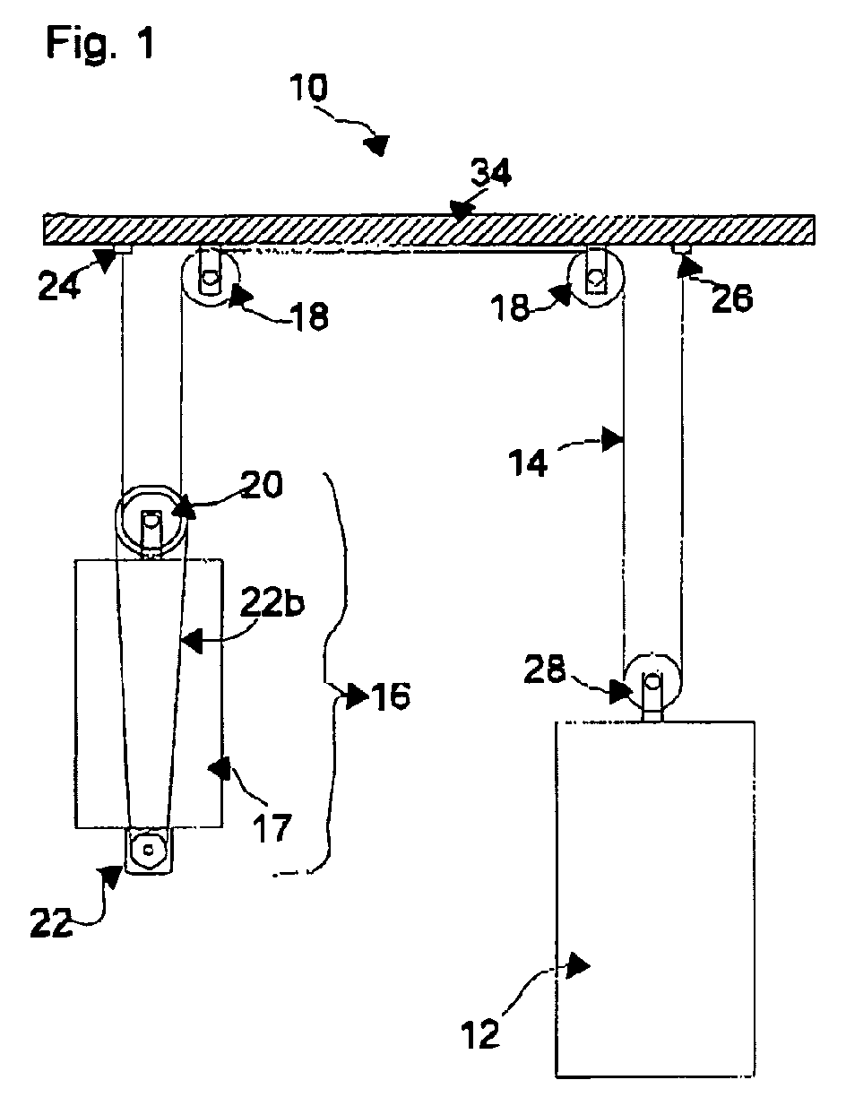
- Fig. 1 shows an embodiment of the elevator installation 10 with an elevator car 12, which is connected by means of suspension 14 with a drive unit 16.
- the suspension means 14, z. B. formed by ropes are about one or more stationary rollers 18 and also deflected by one or more rollers 28 which are connected to the elevator car 12th are provided.
- the first end 24 and the second end 26 of the support means 14 are stationary i. fixed to the building, for example, fixed to the ceiling of the elevator shaft 34.
- the Support means 14 are also in a conventional manner to a rotating disc or roller 20 deflected over 22b z. B. of one or more belts formed, is connected to a drive 22.
- the drive 22 is at the bottom and the rotating disc 20 attached to the top of the counterweight 17.
- the drive unit 16 which also represents the balancing weight, sits down together from the counterweight 17, the drive 22 of the rotating disc or Roller 20 and in this embodiment, the transmission element 22b, bspw. a belt that transfers the energy from the drive 22 to the rotating pulley or pulley 20 transmits.
- Fig. 2 shows an embodiment of the elevator installation 10 with an elevator car 12; the is connected by means of suspension 14 with a drive unit 16.
- the suspension means 14, e.g. formed by ropes are around one or more fixed rollers 18 and as well deflected by one or more rollers 28 provided on the elevator car 12 are.
- the first end 24 and the second end 26 of the support means 14 are stationary, i. Fixed in a building.
- the support means 14 are also in a conventional manner to a rotating disc 20 deflected over 22b z. From one or more Belt formed, is connected to a drive 22.
- the drive 22 is at the Top and the rotating disc 20 at the bottom of the counterweight 17th appropriate.
- Fig. 3 shows an embodiment of the elevator installation 10 with an elevator car 12, the is connected by means of suspension 14 with a drive unit 16.
- the suspension means 14, e.g. formed by ropes are deflected by one or more fixed rollers 18.
- the first end 24 of the support means is stationary d. H. Fixed in a building.
- the second end 26 of the support means 14 is attached to the elevator car.
- the suspension means 14 are also deflected in a conventional manner to a rotating disc 20, the over 22b e.g. formed by one or more belts, with a drive 22nd connected is.
- the drive 22 is at the bottom and the rotating disc 20 at the top of the counterweight 17 attached.
- Fig. 4 shows an embodiment of the elevator installation 10 with an elevator car 12, the is connected by means of suspension 14 with a drive unit 16.
- the suspension means 14, e.g. formed by ropes are deflected by one or more fixed rollers 18.
- the first end 24 of the support means is stationary d. H. Fixed in a building.
- the second end 26 of the support means is attached to the elevator car 12.
- the suspension means 14 are also deflected in a conventional manner to a rotating disc 20, the over 22b z. B. formed by one or more belts, with a drive 22nd connected is.
- the drive 22 is at the top and the rotating disc 20 at attached to the underside of the counterweight 17.
- Fig. 5 shows an embodiment of the elevator installation 10 with an elevator car 12, the is connected by means of suspension 14 with a drive unit 16.
- the suspension means 14, e.g. formed by ropes are deflected by one or more fixed rollers 18.
- the first end 24 of the support means 14 is stationary i. Fixed in a building.
- the second End 26 of the suspension element is attached to the elevator car.
- the suspension means 14 are also deflected in a conventional manner to a rotating disc 20, the is connected to a drive 22.
- the drive 22 and the rotating disc 20 are attached to the top of the counterweight 17.
- Fig. 6 shows an embodiment of the elevator installation 10 with an elevator car 12, the is connected by means of suspension 14 with a drive unit 16.
- the suspension means 14, e.g. formed by ropes are deflected by one or more fixed rollers 18.
- the first end 24 of the support means 14 is stationary d. H. Fixed in a building.
- the second End 26 of the suspension 14 is attached to the elevator car 12.
- the suspension means 14 are also deflected in a conventional manner to a rotating disc 20, the is connected to a drive 22.
- the drive 22 and the rotating disc 20 are attached to the underside of the counterweight 17.
- Fig. 7 shows an embodiment of the elevator installation 10 with an elevator car 12, the is connected by means of suspension 14 with a drive unit 16.
- the suspension means 14, e.g. formed by ropes are around one or more fixed rollers 18 and one the counterweight mounted roller 30 is deflected.
- the first end 24 of the support means 14 is stationary i. Fixed in a building.
- the second end 26 of the support means 14 is at the Elevator car 12 attached.
- the drive 22a is, for example, by a Friction drive formed and acts on the guides 32 of the drive unit 16. Der Drive 22a is at the bottom and the roller 30 at the top of the Counterweight 17 attached.
- Fig. 8 shows an embodiment of the elevator installation 10 with an elevator car 12, the is connected by means of suspension 14 with a drive unit 16.
- the support means 14, z. B. formed by ropes are around one or more stationary rollers 18 and an am Counterweight attached roller 30 deflected.
- the first end 24 of the suspension 14th is stationary d. H. Fixed in a building.
- the second end 26 of the support means 14 is at the Elevator car 12 attached.
- the drive 22a is, for example, by a Friction drive formed and acts on the guides 32 of the drive unit 16. Der Drive 22a is at the top and the roller 30 at the bottom of the Counterweight 17 attached.
Landscapes
- Engineering & Computer Science (AREA)
- Civil Engineering (AREA)
- Mechanical Engineering (AREA)
- Structural Engineering (AREA)
- Cage And Drive Apparatuses For Elevators (AREA)
- Lift-Guide Devices, And Elevator Ropes And Cables (AREA)
- Elevator Control (AREA)
Abstract
Aufzugsanlage mit einer Aufzugskabine (12) und wenigstens einer Antriebseinheit
(16) und einem Ausgleichsgewicht mit Gegengewicht (17), wobei die
Aufzugskabine (12) und das Ausgleichsgewicht mittels wenigstens einem
Tragmittel (14) miteinander verbunden sind, und das wenigstens eine Tragmittel
(14) um wenigstens eine rotierende Scheibe oder Rolle (20) umgelenkt ist, wobei
der wenigstens eine Antrieb (22) und die rotierende Scheibe oder Rolle (20) einen
Teil oder das gesamte Ausgleichsgewicht bilden und mit dem Gegengewicht (17)
zu einer Antriebseinheit (16) verbunden sind und die vom Antrieb (22) angetriebene
rotierende Scheibe oder Rolle (20) an der Oberseite und der Antrieb (22) an der
Unterseite des Gegengewichtes (17) angebracht sind oder dass die vom Antrieb
(22) angetriebene rotierende Scheibe oder Rolle (20) an der Unterseite und der
Antrieb (22) an der Oberseite des Gegengewichtes (17) angebracht sind.
Description
Die Erfindung betrifft eine Aufzugsanlage mit einer Aufzugskabine und wenigstens einer Antriebseinheit und einem Ausgleichsgewicht mit Gegengewicht, wobei die Aufzugskabine und das Ausgleichsgewicht mittels wenigstens einem Tragmittel miteinander verbunden sind, und das wenigstens eine Tragmittel um wenigstens eine rotierende Scheibe oder Rolle umgelenkt ist.The invention relates to an elevator installation with an elevator car and at least a drive unit and a balance weight with counterweight, wherein the Elevator car and the balance weight by means of at least one support means are interconnected, and the at least one support means to at least one rotating disc or roller is deflected.
Bei bekannten Aufzugsanlagen ist der Antrieb, unabhängig von der Art des Antriebs, entweder in einem eigenen Maschinenraum angeordnet oder es handelt sich um einen so genannten maschinenraumlosen Aufzug, bei dem der Antrieb im Schacht unbeweglich, an der Aufzugskabine oder im Gegengewicht angeordnet ist. Die Anordnung im Gegengewicht weist mehrere Nachteile auf, z.B. dass eine spezielle Bauform des Antriebes erforderlich ist und dass der Raum über dem Antrieb im Gegengewicht nicht für den Einbau von Gewichten genützt werden kann und das Gegengewicht daher entsprechend größere Abmessungen aufweisen muss.In known elevator systems, the drive, regardless of the type of drive, either arranged in a separate engine room or it is a so-called machine room-less elevator, in which the drive in the shaft immovable, is arranged on the elevator car or counterweight. The Counterweighting has several disadvantages, e.g. that a special one Design of the drive is required and that the space above the drive in the Counterweight can not be used for the installation of weights and that Counterweight therefore must have correspondingly larger dimensions.
Bei den Tragmitteln kann es sich um Tragseile, Ketten, Riemen oder dergleichen handeln. Die rotierende Scheibe kann von einer Treibscheibe, einem Kettenrad, einem Riemenrad oder dergleichen gebildet sein.The suspension elements may be suspension cables, chains, belts or the like act. The rotating disk can be made of a traction sheave, a sprocket, a Pulley or the like may be formed.
In Kenntnis dieser Gegebenheiten liegt der Erfindung die Aufgabe zugrunde, eine Aufzugsanlage der eingangs genannten Art zu schaffen, bei der der Materialbedarf für das Ausgleichsgewicht reduziert ist, die Abmessungen möglichst gering sind und bei der frei am Markt erhältliche Antriebe eingesetzt werden können.In knowledge of these circumstances, the invention has the object, a To provide elevator installation of the type mentioned, in which the material requirement for the balance weight is reduced, the dimensions are as small as possible and at the freely available on the market drives can be used.
Diese Aufgabe wird erfindungsgemäß dadurch gelöst, dass der wenigstens eine Antrieb und die rotierende Scheibe oder Rolle einen Teil oder das gesamte Ausgleichsgewicht bilden und mit dem Gegengewicht zu einer Antriebseinheit verbunden sind und die vom Antrieb angetriebene rotierende Scheibe oder Rolle an der Oberseite und der Antrieb an der Unterseite des Gegengewichtes angebracht sind oder dass die vom Antrieb angetriebene rotierende Scheibe oder Rolle an der Unterseite und der Antrieb an der Oberseite des Gegengewichtes angebracht sind. This object is achieved in that the at least one Drive and the rotating disk or roll a part or the whole Compensating weight and with the counterweight to a drive unit connected to and driven by the drive rotating disc or roller the top and the drive are mounted at the bottom of the counterweight or that the driven by the drive rotating disc or roller on the Bottom and the drive are mounted at the top of the counterweight.
Der Antrieb einer solchen Aufzugsanlage kann mit oder ohne Getriebe z. B. als Reibrad-, Riemen- oder Treibscheibenantrieb ausgeführt werden. Der Antrieb kann einen eintourigen, polumschalibaren oder einen geregelten Antriebsmotor aufweisen.The drive of such a lift system can be with or without gear z. B. as Reibrad-, belt or traction sheave drive are performed. The drive can have a single-speed, polumschalibaren or a regulated drive motor.
Durch eine solche Verbindung von Antrieb und Gegengewicht zu einer Antriebseinheit und zu einem Ausgleichsgewicht kann das Gegengewicht entsprechend geringer dimensioniert werden. Die Trennung von rotierender Scheibe oder Rolle und Antrieb weist den weiteren Vorteil auf, dass der Zugang zum Antrieb zur Wartung oder zur Reparatur erleichtert ist.By such a combination of drive and counterweight to a drive unit and to a balance weight, the counterweight can be correspondingly lower be dimensioned. The separation of rotating disc or roller and drive has the further advantage that access to the drive for maintenance or Repair is easier.
Definitionen gemäß EN 81-1:1998:
- Ausgleichsgewicht: Masse die der Energieeinsparung dadurch dient, dass sie die gesamte oder einen Teil der Masse des Fahrkorbes ausgleicht
- Gegengewicht: Masse, die die Treibfähigkeit sicherstellt
- Balancing weight: mass that serves to save energy by balancing all or part of the mass of the car
- Counterweight: Mass that ensures the propulsion
In einer bevorzugten Ausführungsvariante ist vorgesehen, dass die Scheibe oder Rolle und der Antrieb durch ein Übertragungselement in Antriebsverbindung, vorzugsweise über einen Riemen, stehen. Es ist dann z.B. auch möglich, dass die Antriebsverbindung ein Zahnradantrieb oder ein Keilriemenantrieb ist.In a preferred embodiment, it is provided that the disc or roller and the drive by a transmission element in drive connection, preferably over a belt, stand. It is then e.g. also possible that the Drive connection is a gear drive or a V-belt drive.
Eine solche Ausführung hat den Vorteil einer einfachen Verbindung von Antrieb und rotierender Scheibe oder Rolle.Such a design has the advantage of a simple connection of drive and rotating disc or roller.
In einer weiteren bevorzugten Ausführungsvariante ist vorgesehen, dass die Aufhängung der Aufzugskabine und die Aufhängung der Antriebseinheit derart erfolgt, dass die Fahrgeschwindigkeit der Aufzugskabine höher ist, als die der Antriebseinheit. Eine solche Ausführung kann z.B. dadurch realisiert werden, dass das eine Ende des über das Gegengewicht und über mindestens eine ortsfest gelagerte Rolle geführte Tragmittel ortsfest befestigt ist und das andere Ende des Tragmittels direkt an der Aufzugskabine befestigt ist.In a further preferred embodiment, it is provided that the Suspension of the elevator car and the suspension of the drive unit takes place in such a way that the driving speed of the elevator car is higher than that of the drive unit. Such an embodiment may e.g. be realized by the one end of the guided over the counterweight and at least one stationary mounted role Supporting means is fixed in place and the other end of the suspension means directly to the Elevator car is attached.
Die Aufhängung kann in einer solchen Ausführungsvariante nach Art eines Flaschenzuges realisiert werden, d.h. bei einem einfachen Flaschenzug wird das Antriebsmittel bzw. Tragmittel an der Aufzugskabine befestigt und über zumindest eine ortsfeste Rolle und dann die rotierende Scheibe oder Rolle des Ausgleichsgewichtes geführt. Das gegenüberliegende Ende des Antriebs bzw. Tragmittels ist wiederum ortsfest, d.h. z.B. am oberen Ende des Aufzugschachtes fixiert. In diesem Fall ist ein einfacher 1:2 Flaschenzug realisiert. Das Ausgleichsgewicht mit der Antriebseinheit legt also den halben Weg zurück wie die Aufzugskabine. Ein daraus resultierender Vorteil ist, dass der Schacht für das Ausgleichsgewicht kürzer dimensioniert werden kann.The suspension can in such a variant of the type Pulley to be realized, i. in a simple pulley is the Drive means or suspension means attached to the elevator car and at least one fixed roller and then the rotating disc or roller of the balance weight guided. The opposite end of the drive or support means is in turn stationary, i. e.g. fixed at the upper end of the elevator shaft. In this case is a simple 1: 2 pulley realized. The balance weight with the drive unit So it's half way back like the elevator car. A resulting The advantage is that the shaft is dimensioned shorter for the balance weight can.
Darüber hinaus betrifft die Erfindung eine gattungsgemäße Aufzugsanlage, bei der der Antrieb und die rotierende Scheibe oder Rolle einen Teil oder das gesamte Ausgleichsgewicht bilden und mit dem Gegengewicht zu einer Antriebseinheit verbunden werden und die Aufhängung der Aufzugskabine und die Aufhängung der Antriebseinheit derart erfolgt, dass die Fahrgeschwindigkeit der Aufzugskabine höher ist, als die der Antriebseinheit. Dies wird bspw. dadurch erreicht, dass das das wenigstens eine Tragmittel über die Antriebseinheit und über mindestens eine ortsfest gelagerte Rolle geführt wird, wobei das eine Ende des Tragmittels ortsfest und das andere Ende des Tragmittels direkt an der Aufzugskabine befestigt ist.In addition, the invention relates to a generic elevator system in which the Drive and the rotating disk or roll a part or the whole Compensating weight and with the counterweight to a drive unit be connected and the suspension of the elevator car and the suspension of the Drive unit is made such that the driving speed of the elevator car higher is as the drive unit. This is achieved, for example, by the fact that the at least one support means via the drive unit and at least one stationary mounted roller is guided, wherein the fixed one end of the support means and the other end of the suspension element is attached directly to the elevator car.
Eine derartige Aufhängung von Aufzugskabine und Antriebseinheit kann ebenfalls durch Flaschenzugmechanismen erfolgen. Günstig hat es sich herausgestellt, wenn der Antrieb und die rotierende Scheibe oder Rolle an der Oberseite des Gegengewichtes angebracht sind oder in einer anderen Ausführungsvariante, wenn der Antrieb und die rotierende Scheibe oder Rolle an der Unterseite des Gegengewichtes angebracht sind.Such a suspension of elevator car and drive unit can also done by pulley mechanisms. Conveniently it turned out, though the drive and the rotating disc or roller at the top of the Counterweight are appropriate or in another variant, if the drive and the rotating disc or roller at the bottom of the Counterweight are appropriate.
Eine derartige Anordnung von Antrieb und rotierender Scheibe oder Rolle hat den Vorteil einer besonders einfachen Montage am Gegengewicht. In einer Ausführungsvariante ist vorgesehen, dass die vom Antrieb angetriebene rotierende Scheibe oder Rolle an der Oberseite und der Antrieb an der Unterseite des Gegengewichtes angebracht sind oder dass die vom Antrieb angetriebene rotierende Scheibe oder Rolle an der Unterseite und der Antrieb an der Oberseite des Gegengewichtes angebracht sind. In dieser Ausführung ist der Zugang zum Antrieb aufgrund der Trennung zur rotierenden Scheibe oder Rolle erleichtert. Such an arrangement of drive and rotating disc or roller has the Advantage of a particularly simple mounting on the counterweight. In a Variant is provided that the driven by the drive rotating Disc or roller at the top and the drive at the bottom of the Are mounted counterweight or that the driven by the drive rotating Disc or roller at the bottom and the drive at the top of the Counterweight are appropriate. In this version is the access to the drive facilitated due to the separation to the rotating disc or roller.
In einer weiteren Ausführungsvariante ist vorgesehen, dass der Antrieb des Gegengewichtes über ein Antriebselement an einer raumfest angeordneten Schiene angreift. Eine solche Anordnung hat z.B. den Vorteil, dass keine Verbindung von Antrieb zu rotierender Scheibe oder Rolle erforderlich ist. Insbesondere bei einer räumlichen Trennung von Antrieb und rotierender Scheibe oder Rolle ist dies vorteilhaft.In a further embodiment, it is provided that the drive of the Counterweight via a drive element on a spatially fixed rail attacks. Such an arrangement has e.g. the advantage that no connection of Drive to rotating disc or roller is required. Especially with a Spatial separation of drive and rotating pulley or roller is this advantageous.
Eine derartige Anordnung lässt sich bspw. dadurch realisieren, dass der Antrieb zwischen Antriebselement und Schiene über ein Reibrad erfolgt oder in einer anderen Ausführungsvariante dadurch, dass der Antrieb zwischen Antriebselement und Schiene über Ritzel und Zahnstange erfolgt. Der Antrieb erfolgt dann also nicht mehr über die rotierende Scheibe oder Rolle wie in einigen der oberen Ausführungsvarianten, sondern direkt über den Aufzugsschacht, in dem bspw. ein Reibrad des Antriebes an einer ortsfesten Schiene angreift und das Gegengewicht auf- und abwärts bewegt, wodurch auch die Aufzugskabine die entgegen gesetzte Ab- und Aufwärtsbewegung mitmacht. Ein solcher Reibradantrieb kann bspw. dadurch realisiert werden, dass zwei Räder eine Schiene in der Mitte einklemmen und durch gegengleiche Rotation der Räder erfolgt die Bewegung entlang der Schiene. Bei einem Antrieb mit Zahnstange und Ritzel greifen die Ritzel in die Zahnstange und bewegen dadurch das Gegengewicht nach oben oder nach unten. Beide Antriebsmechanismen können nach bekanntem Stand der Technik erfolgen, d.h. auch andere Antriebsmechanismen sind möglich.Such an arrangement can, for example, be realized by the drive between the drive element and rail via a friction wheel or in another Variant in that the drive between the drive element and rail done via pinion and rack. The drive is then no longer on the rotating disc or roller as in some of the upper embodiments, but directly over the elevator shaft, in which, for example, a friction wheel of the drive a stationary rail attacks and moves the counterweight up and down, whereby the elevator car the opposite upward and downward movement participates. Such a friction wheel drive can, for example, be realized in that two Clamp a rail in the middle and by opposite rotation of the Wheels move along the rail. For a drive with rack and pinions engage the pinions in the rack and thereby move the Counterweight up or down. Both drive mechanisms can after Known prior art, i. also other drive mechanisms are possible.
In einer weiteren Ausführungsvariante ist vorgesehen, dass das wenigstens eine Tragmittel ein Seil ist. Ein solches Tragmittel ist besonders einfach in der Wartung und Montage. Ein derartiges Seil kann in an sich bekannter Weise ausgeführt sein bspw. als Stahlseil.In a further embodiment, it is provided that the at least one Supporting means is a rope. Such a suspension is particularly easy to maintain and Assembly. Such a rope can be carried out in a conventional manner, for example. as a steel cable.
Weitere Einzelheiten, Merkmale und Vorteile ergeben sich aus den nachfolgenden Beschreibungen der Figuren einiger Ausführungsbeispiele von erfindungsgemäßen Aufzugsanlagen. Die Figuren 1 bis 8 zeigen in schematischer Darstellung mögliche Ausführungsformen der Aufzugsanlage.
- Fig. 1
- zeigt schematisch eine erfindungsgemäße Ausführungsform einer Aufzugsanlage, bei der der Antrieb an der Unterseite des Gegengewichtes liegt und die rotierende Scheibe oder Rolle an der Oberseite des Gegengewichtes liegt, wobei das Tragmittel an beiden Enden am Aufzugsschacht fixiert ist.
- Fig. 2
- zeigt in schematischer Form eine der Fig. 1 analogen Aufzugsanlage, wobei im Unterschied zur Fig. 1 der Antrieb an der Oberseite und die rotierende Scheibe oder Rolle an der Unterseite des Gegengewichts angebracht ist.
- Fig. 3
- zeigt eine der Fig. 1 analogen Aufzugsanlage, wobei hier das Tragmittel an einem Ende am Aufzugsschacht montiert ist und am anderen Ende an der Aufzugskabine fixiert ist.
- Fig. 4
- zeigt eine der Fig. 2 analogen Ausführungsvariante, wobei hier das Tragmittel an einem Ende am Aufzugsschacht und am anderen Ende an der Aufzugskabine montiert ist.
- Fig. 5
- zeigt ein Ausführungsbeispiel einer erfindungsgemäßen Aufzugsanlage, wo Antrieb und rotierende Scheibe an der Oberseite des Gegengewichtes montiert sind, wobei das Tragmittel an einem Ende am Aufzugsschacht und am anderen Ende an der Aufzugskabine montiert ist.
- Fig. 6
- zeigt eine erfindungsgemäße Ausführungsvariante einer Aufzugsanlage, bei der der Antrieb und die rotierende Scheibe oder Rolle an der Unterseite des Gegengewichtes angebracht sind und bei dem das eine Ende des Tragmittels am Aufzugsschacht und das andere Ende des Tragmittels an der Aufzugskabine fixiert ist.
- Fig.7
- zeigt eine Ausführungsvariante einer erfindungsgemäßen Aufzugsanlage, bei der die rotierende Scheibe oder Rolle an der Oberseite des Gegengewichtes sitzen und das Tragmittel an einem Ende am Aufzugsschacht und am anderen Ende an der Aufzugskabine fixiert sind, wobei der Antrieb nicht über die Rolle auf das Tragmittel erfolgt, sondern durch einen Reibradantrieb erfolgt.
- Fig. 8
- zeigt eine Ausführungsvariante einer Aufzugsanlage, bei der der Antrieb an der Oberseite des Gegengewichtes liegt und die rotierende Scheibe oder Rolle an der Unterseite des Gegengewichtes liegt, wobei das eine Ende des Tragmittels an der Aufzugskabine fixiert ist und das andere Ende des Tragmittels am Aufzugsschacht fixiert ist.
- Fig. 1
- schematically shows an embodiment of an elevator system according to the invention, wherein the drive is located on the underside of the counterweight and the rotating disc or roller is located at the top of the counterweight, wherein the support means is fixed at both ends to the elevator shaft.
- Fig. 2
- 1 schematically shows an elevator system analogous to that of FIG. 1, wherein, in contrast to FIG. 1, the drive is mounted on the upper side and the rotating disk or roller is mounted on the lower side of the counterweight.
- Fig. 3
- shows an analogous to Fig. 1 elevator system, in which case the support means is mounted at one end to the elevator shaft and is fixed to the other side of the elevator car.
- Fig. 4
- shows an embodiment similar to Fig. 2, in which case the suspension element is mounted at one end to the elevator shaft and at the other end to the elevator car.
- Fig. 5
- shows an embodiment of an elevator system according to the invention, where drive and rotating disc are mounted on the top of the counterweight, wherein the support means is mounted at one end to the elevator shaft and at the other end to the elevator car.
- Fig. 6
- shows an embodiment of an elevator system according to the invention, in which the drive and the rotating disc or roller are mounted on the underside of the counterweight and in which one end of the support means is fixed to the elevator shaft and the other end of the suspension means to the elevator car.
- Figure 7
- shows an embodiment of an elevator system according to the invention, in which the rotating disc or roller sitting at the top of the counterweight and the suspension means are fixed at one end to the elevator shaft and at the other end to the elevator car, wherein the drive is not via the roller on the support means, but by a friction wheel drive.
- Fig. 8
- shows an embodiment of an elevator system, wherein the drive is located at the top of the counterweight and the rotating disc or roller is located on the underside of the counterweight, wherein one end of the support means is fixed to the elevator car and the other end of the support means is fixed to the elevator shaft ,
Fig. 1 zeigt eine Ausführungsvariante der Aufzugsanlage 10 mit einer Aufzugskabine
12, die mittels Tragmittel 14 mit einer Antriebseinheit 16 verbunden ist. Die Tragmittel
14, z. B. von Seilen gebildet, sind um eine oder mehrere ortsfeste Rollen 18 und
außerdem um eine oder mehrere Rollen 28 umgelenkt, die an der Aufzugskabine 12
vorgesehen sind. Das erste Ende 24 und das zweite Ende 26 der Tragmittel 14 sind
ortsfest d.h. gebäudefest bspw. an der Decke des Aufzugschachtes 34 fixiert. Die
Tragmittel 14 sind außerdem in an sich bekannter Weise um eine rotierende Scheibe
oder Rolle 20 umgelenkt, die über 22b z. B. von einem oder mehreren Riemen
gebildet, mit einem Antrieb 22 verbunden ist. Der Antrieb 22 ist an der Unterseite und
die rotierende Scheibe 20 an der Oberseite des Gegengewichtes 17 angebracht.Fig. 1 shows an embodiment of the
Die Antriebseinheit 16, die auch gleichzeitig das Ausgleichsgewicht darstellt, setzt sich
zusammen aus dem Gegengewicht 17, dem Antrieb 22 der rotierenden Scheibe oder
Rolle 20 und in dieser Ausführungsvariante dem Übertragungselement 22b, bspw.
einem Riemen, der die Energie vom Antrieb 22 auf die rotierende Scheibe oder Rolle
20 überträgt.The
Fig. 2 zeigt eine Ausbildung der Aufzugsanlage 10 mit einer Aufzugskabine 12; die
mittels Tragmitteln 14 mit einer Antriebseinheit 16 verbunden ist. Die Tragmittel 14,
z.B. von Seilen gebildet, sind um eine oder mehrere ortsfeste Rollen 18 und außerdem
um eine oder mehrere Rollen 28 umgelenkt, die an der Aufzugskabine 12 vorgesehen
sind. Das erste Ende 24 und das zweite Ende 26 der Tragmittel 14 sind ortsfest, d.h.
gebäudefest fixiert. Die Tragmittel 14 sind außerdem in an sich bekannter Weise um
eine rotierende Scheibe 20 umgelenkt, die über 22b z. B. von einem oder mehreren
Riemen gebildet, mit einem Antrieb 22 verbunden ist. Der Antrieb 22 ist an der
Oberseite und die rotierende Scheibe 20 an der Unterseite des Gegengewichtes 17
angebracht.Fig. 2 shows an embodiment of the
Fig. 3 zeigt eine Ausbildung der Aufzugsanlage 10 mit einer Aufzugskabine 12, die
mittels Tragmitteln 14 mit einer Antriebseinheit 16 verbunden ist. Die Tragmittel 14,
z.B. von Seilen gebildet, sind um eine oder mehrere ortsfeste Rollen 18 umgelenkt.
Das erste Ende 24 der Tragmittel ist ortsfest d. h. gebäudefest fixiert. Das zweite Ende
26 der Tragmittel 14 ist an der Aufzugskabine befestigt. Die Tragmittel 14 sind
außerdem in an sich bekannter Weise um eine rotierende Scheibe 20 umgelenkt, die
über 22b z.B. von einem oder mehreren Riemen gebildet, mit einem Antrieb 22
verbunden ist. Der Antrieb 22 ist an der Unterseite und die rotierende Scheibe 20 an
der Oberseite des Gegengewichtes 17 angebracht.Fig. 3 shows an embodiment of the
Während die Aufhängungen von Antriebseinheit 16 und Aufzugskabine 12 in den
Ausführungsbeispielen von Fig. 1 und Fig. 2 entsprechend einem doppelten
Flaschenzug beschrieben werden könnten, wobei sich die Wirkungsweise der
Flaschenzüge gegenseitig neutralisieren, ist die Aufhängung von Antriebseinheit 16 zu
Aufzugskabine 12 in den Ausführungsbeispielen von Fig. 3 bis 8 entsprechende einem
1:2 Flaschenzug, d.h. an der Aufzugskabine 12 ist ein einfacher Kraftstrang und am
Ausgleichsgewicht teilt sich die Kraft auf zwei Kraftstränge auf, wodurch der 1:2
Flaschenzugmechanismus erreicht wird. Selbstverständlich ist es auch denkbar, durch
geeignete Anordnung von ortsfesten und beweglichen Rollen 18, 28, Flaschenzüge mit
anderer Übersetzung zu realisieren, bspw. 1:3, 1:4 usw.While the suspensions of
Fig. 4 zeigt eine Ausbildung der Aufzugsanlage 10 mit einer Aufzugskabine 12, die
mittels Tragmitteln 14 mit einer Antriebseinheit 16 verbunden ist. Die Tragmittel 14,
z.B. von Seilen gebildet, sind um eine oder mehrere ortsfeste Rollen 18 umgelenkt.
Das erste Ende 24 der Tragmittel ist ortsfest d. h. gebäudefest fixiert. Das zweite Ende
26 der Tragmittel ist an der Aufzugskabine 12 befestigt. Die Tragmittel 14 sind
außerdem in an sich bekannter Weise um eine rotierende Scheibe 20 umgelenkt, die
über 22b z. B. von einem oder mehreren Riemen gebildet, mit einem Antrieb 22
verbunden ist. Der Antrieb 22 ist an der Oberseite und die rotierende Scheibe 20 an
der Unterseite des Gegengewichtes 17 angebracht.Fig. 4 shows an embodiment of the
Fig. 5 zeigt eine Ausbildung der Aufzugsanlage 10 mit einer Aufzugskabine 12, die
mittels Tragmitteln 14 mit einer Antriebseinheit 16 verbunden ist. Die Tragmittel 14,
z.B. von Seilen gebildet, sind um eine oder mehrere ortsfeste Rollen 18 umgelenkt.
Das erste Ende 24 der Tragmittel 14 ist ortsfest d.h. gebäudefest fixiert. Das zweite
Ende 26 der Tragmittel ist an der Aufzugskabine befestigt. Die Tragmittel 14 sind
außerdem in an sich bekannter Weise um eine rotierende Scheibe 20 umgelenkt, die
mit einem Antrieb 22 verbunden ist. Der Antrieb 22 und die rotierende Scheibe 20 sind
an der Oberseite des Gegengewichtes 17 angebracht.Fig. 5 shows an embodiment of the
Fig. 6 zeigt eine Ausbildung der Aufzugsanlage 10 mit einer Aufzugskabine 12, die
mittels Tragmitteln 14 mit einer Antriebseinheit 16 verbunden ist. Die Tragmittel 14,
z.B. von Seilen gebildet, sind um eine oder mehrere ortsfeste Rollen 18 umgelenkt.
Das erste Ende 24 der Tragmittel 14 ist ortsfest d. h. gebäudefest fixiert. Das zweite
Ende 26 der Tragmittel 14 ist an der Aufzugskabine 12 befestigt. Die Tragmittel 14 sind
außerdem in an sich bekannter Weise um eine rotierende Scheibe 20 umgelenkt, die
mit einem Antrieb 22 verbunden ist. Der Antrieb 22 und die rotierende Scheibe 20 sind
an der Unterseite des Gegengewichtes 17 angebracht.Fig. 6 shows an embodiment of the
Fig. 7 zeigt eine Ausbildung der Aufzugsanlage 10 mit einer Aufzugskabine 12, die
mittels Tragmitteln 14 mit einer Antriebseinheit 16 verbunden ist. Die Tragmittel 14,
z.B. von Seilen gebildet, sind um eine oder mehrere ortsfeste Rollen 18 und um eine
am Gegengewicht angebrachte Rolle 30 umgelenkt. Das erste Ende 24 der Tragmittel
14 ist ortsfest d.h. gebäudefest fixiert. Das zweite Ende 26 der Tragmittel 14 ist an der
Aufzugskabine 12 befestigt. Der Antrieb 22a wird beispielsweise durch einen
Reibradantrieb gebildet und wirkt auf die Führungen 32 der Antriebseinheit 16. Der
Antrieb 22a ist an der Unterseite und die Rolle 30 an der Oberseite des
Gegengewichtes 17 angebracht.Fig. 7 shows an embodiment of the
Fig. 8 zeigt eine Ausbildung der Aufzugsanlage 10 mit einer Aufzugskabine 12, die
mittels Tragmitteln 14 mit einer Antriebseinheit 16 verbunden ist. Die Tragmittel 14, z.
B. von Seilen gebildet, sind um eine oder mehrere ortsfeste Rollen 18 und um eine am
Gegengewicht angebrachte Rolle 30 umgelenkt. Das erste Ende 24 der Tragmittel 14
ist ortsfest d. h. gebäudefest fixiert. Das zweite Ende 26 der Tragmittel 14 ist an der
Aufzugskabine 12 befestigt. Der Antrieb 22a wird beispielsweise durch einen
Reibradantrieb gebildet und wirkt auf die Führungen 32 der Antriebseinheit 16. Der
Antrieb 22a ist an der Oberseite und die Rolle 30 an der Unterseite des
Gegengewichtes 17 angebracht.Fig. 8 shows an embodiment of the
Mit der Erfindung können beispielsweise die folgenden Vorteile erreicht werden:
- Es sind verschiedene Aufhängungsvarianten realisierbar, mit denen die Leistungsaufnahme des Antriebes bei herkömmlichen Fahrgeschwindigkeiten reduziert werden kann oder bei hohen Fahrgeschwindigkeiten gering sein kann,
- Die Aufzugsanlage ist mit sämtlichen herkömmlichen Antrieben ausrüstbar (mit oder ohne Getriebe, Reibrad-, Riemen-, Treibscheibenantrieb oder dergleichen),
- Die Achslage und die Anordnung der losen und der ortsfesten Rollen ist variabel,
- Die Schachtabmessungen können z. B. über dem Fahrweg der Antriebseinheit verringert werden.
- Various suspension variants can be realized with which the power consumption of the drive can be reduced at conventional driving speeds or can be low at high driving speeds,
- The lift system can be equipped with all conventional drives (with or without gear, friction wheel, belt, traction sheave drive or the like),
- The axis position and the arrangement of the loose and fixed rollers is variable,
- The shaft dimensions can z. B. be reduced over the travel of the drive unit.
Bei den gezeigten Ausführungsbeispielen, bei denen das eine Ende 26 des Tragmittels
14 direkt an der Aufzugskabine 12 fixiert ist, wurde die Aufhängungsvorrichtung immer
an der Oberseite der Aufzugskabine 12 realisiert. Selbstverständlich sind im Rahmen
der Erfindung auch andere Aufhängungsvarianten vorgesehen, bspw. so genannte
Rucksackaufhängungen, das sind Aufhängungen, bei denen das Ende 26 des
Tragmittels 14 auf der Seite der Aufzugskabine 12 angebracht ist, insbesondere an der
dem Ausgleichsgewicht benachbarten Seite. Auch eine Umlenkung der Tragmittel 14
an der Unterseite der Aufzugskabine 12 mit entsprechenden Rollen 28 ist möglich. In the embodiments shown, in which one
- 1010
- Aufzugsanlageelevator system
- 1212
- Aufzugskabine (von 10)Elevator cabin (from 10)
- 1414
- Tragmittel (von 10)Supporting means (of 10)
- 1616
- Antriebseinheit (von 10)Drive unit (out of 10)
- 1717
- Gegengewicht (von 10)Counterweight (from 10)
- 1818
- ortsfeste Rollenfixed rollers
- 2020
- rotierende Scheibe (von 10)rotating disc (from 10)
- 2222
- Antrieb (für 20) und Ausgleichsgewicht (für 12)Drive (for 20) and balance weight (for 12)
- 22a22a
- Antrieb (auf Führung von 16 wirkend) und Ausgleichsgewicht (für 12)Drive (acting on guide of 16) and balance weight (for 12)
- 22b22b
- Verbindung (von 20 und 22)Connection (from 20 and 22)
- 2424
- erstes Ende des Tragmittels (von 14)first end of the suspension element (from 14)
- 2626
- zweites Ende des Tragmittels (von 14)second end of the suspension element (from 14)
- 2828
- Rollen (von 12)Rolls (from 12)
- 3030
- Rolle (von 16)Roll (from 16)
- 3232
- Führung (für 16)Leadership (for 16)
- 3434
- Gebäudeteil oder RollenträgerBuilding part or roller carrier
Claims (14)
Applications Claiming Priority (2)
| Application Number | Priority Date | Filing Date | Title |
|---|---|---|---|
| DE102004010528 | 2004-03-04 | ||
| DE102004010528 | 2004-03-04 |
Publications (3)
| Publication Number | Publication Date |
|---|---|
| EP1574472A2 true EP1574472A2 (en) | 2005-09-14 |
| EP1574472A3 EP1574472A3 (en) | 2006-08-16 |
| EP1574472B1 EP1574472B1 (en) | 2007-12-12 |
Family
ID=34813603
Family Applications (1)
| Application Number | Title | Priority Date | Filing Date |
|---|---|---|---|
| EP05004505A Expired - Lifetime EP1574472B1 (en) | 2004-03-04 | 2005-03-02 | Elevator system with driving gear incorporated in the counterweight |
Country Status (5)
| Country | Link |
|---|---|
| EP (1) | EP1574472B1 (en) |
| AT (1) | ATE380774T1 (en) |
| DE (1) | DE502005002182D1 (en) |
| ES (1) | ES2297550T3 (en) |
| PT (1) | PT1574472E (en) |
Cited By (2)
| Publication number | Priority date | Publication date | Assignee | Title |
|---|---|---|---|---|
| US8109367B2 (en) * | 2006-06-14 | 2012-02-07 | Inventio Ag | Counterweight and suspension for an elevator without an engine room |
| EP2497739A1 (en) * | 2011-03-10 | 2012-09-12 | Hansruedi Diethelm | Lift |
Family Cites Families (5)
| Publication number | Priority date | Publication date | Assignee | Title |
|---|---|---|---|---|
| FI95687C (en) * | 1993-06-28 | 1996-03-11 | Kone Oy | Counterweight elevator machine / elevator motor |
| US6138799A (en) * | 1998-09-30 | 2000-10-31 | Otis Elevator Company | Belt-climbing elevator having drive in counterweight |
| JP4530544B2 (en) * | 1998-12-11 | 2010-08-25 | 東芝エレベータ株式会社 | Elevator equipment |
| WO2000053520A1 (en) * | 1999-03-08 | 2000-09-14 | Hitachi, Ltd. | Elevator |
| EP2390221A1 (en) * | 2003-02-19 | 2011-11-30 | Mitsubishi Denki Kabushiki Kaisha | Elevator |
-
2005
- 2005-03-02 ES ES05004505T patent/ES2297550T3/en not_active Expired - Lifetime
- 2005-03-02 EP EP05004505A patent/EP1574472B1/en not_active Expired - Lifetime
- 2005-03-02 PT PT05004505T patent/PT1574472E/en unknown
- 2005-03-02 AT AT05004505T patent/ATE380774T1/en active
- 2005-03-02 DE DE502005002182T patent/DE502005002182D1/en not_active Expired - Lifetime
Cited By (2)
| Publication number | Priority date | Publication date | Assignee | Title |
|---|---|---|---|---|
| US8109367B2 (en) * | 2006-06-14 | 2012-02-07 | Inventio Ag | Counterweight and suspension for an elevator without an engine room |
| EP2497739A1 (en) * | 2011-03-10 | 2012-09-12 | Hansruedi Diethelm | Lift |
Also Published As
| Publication number | Publication date |
|---|---|
| EP1574472B1 (en) | 2007-12-12 |
| EP1574472A3 (en) | 2006-08-16 |
| ES2297550T3 (en) | 2008-05-01 |
| DE502005002182D1 (en) | 2008-01-24 |
| ATE380774T1 (en) | 2007-12-15 |
| PT1574472E (en) | 2008-03-12 |
Similar Documents
| Publication | Publication Date | Title |
|---|---|---|
| DE69417202T2 (en) | Buffer structure | |
| EP1640308B1 (en) | Positioning of a driving machine for elevators | |
| DE29924747U1 (en) | Elevator system with drive motor between elevator car and elevator shaft side wall | |
| EP1588977B1 (en) | Device for the leveling of the cars of a multi-deck elevator | |
| EP2082983A1 (en) | Lift assembly | |
| EP3119713A1 (en) | Elevator comprising balance rope tensioning device | |
| WO2002068307A1 (en) | Arrangement for weight compensating elements | |
| DE102012100791A1 (en) | Winch device for steep conveyer system in e.g. opencast mining, has pulley-blocks arranged between driving wheel arrangements and masses, traction units forming pulley-blocks, where wheel arrangements are unwound from traction units | |
| EP3732124B1 (en) | Device for parking vehicles | |
| DE3523187A1 (en) | Lift in buildings | |
| DE112005003475T5 (en) | Elevator car with an angled beam stranding arrangement | |
| EP1574472B1 (en) | Elevator system with driving gear incorporated in the counterweight | |
| DE10140390B4 (en) | vertical lift | |
| DE102004043298B4 (en) | Drive on a cabin for vertical lifts | |
| EP3080029B1 (en) | Lift assembly | |
| EP1183204B1 (en) | Elevator in which the drive is mounted in the counterweight | |
| WO2010072656A1 (en) | A plurality of elevator cars in an elevator shaft with improved shaft utilization | |
| CH406565A (en) | Cable lift | |
| EP1437322B1 (en) | Traction sheave elevator | |
| EP1656318A1 (en) | Elevator | |
| DE102006037253A1 (en) | Elevator, with a cabin and a counterweight, has a cabin support cable with no drive function and a drive cable in a pulley structure moving the counterweight to shift the cabin | |
| EP1935826B1 (en) | Lift system | |
| DE69826819T2 (en) | Elevator with on-board drive device | |
| DE10394023T5 (en) | Drive module arrangement for specialist gas conveying means | |
| DE1210530B (en) | Elevator equipment |
Legal Events
| Date | Code | Title | Description |
|---|---|---|---|
| PUAI | Public reference made under article 153(3) epc to a published international application that has entered the european phase |
Free format text: ORIGINAL CODE: 0009012 |
|
| AK | Designated contracting states |
Kind code of ref document: A2 Designated state(s): AT BE BG CH CY CZ DE DK EE ES FI FR GB GR HU IE IS IT LI LT LU MC NL PL PT RO SE SI SK TR |
|
| AX | Request for extension of the european patent |
Extension state: AL BA HR LV MK YU |
|
| PUAL | Search report despatched |
Free format text: ORIGINAL CODE: 0009013 |
|
| AK | Designated contracting states |
Kind code of ref document: A3 Designated state(s): AT BE BG CH CY CZ DE DK EE ES FI FR GB GR HU IE IS IT LI LT LU MC NL PL PT RO SE SI SK TR |
|
| AX | Request for extension of the european patent |
Extension state: AL BA HR LV MK YU |
|
| 17P | Request for examination filed |
Effective date: 20070201 |
|
| AKX | Designation fees paid |
Designated state(s): AT BE BG CH CY CZ DE DK EE ES FI FR GB GR HU IE IS IT LI LT LU MC NL PL PT RO SE SI SK TR |
|
| GRAP | Despatch of communication of intention to grant a patent |
Free format text: ORIGINAL CODE: EPIDOSNIGR1 |
|
| GRAS | Grant fee paid |
Free format text: ORIGINAL CODE: EPIDOSNIGR3 |
|
| GRAA | (expected) grant |
Free format text: ORIGINAL CODE: 0009210 |
|
| AK | Designated contracting states |
Kind code of ref document: B1 Designated state(s): AT BE BG CH CY CZ DE DK EE ES FI FR GB GR HU IE IS IT LI LT LU MC NL PL PT RO SE SI SK TR |
|
| REG | Reference to a national code |
Ref country code: GB Ref legal event code: FG4D Free format text: NOT ENGLISH |
|
| REG | Reference to a national code |
Ref country code: CH Ref legal event code: EP |
|
| REG | Reference to a national code |
Ref country code: IE Ref legal event code: FG4D Free format text: LANGUAGE OF EP DOCUMENT: GERMAN |
|
| REF | Corresponds to: |
Ref document number: 502005002182 Country of ref document: DE Date of ref document: 20080124 Kind code of ref document: P |
|
| REG | Reference to a national code |
Ref country code: CH Ref legal event code: NV Representative=s name: ISLER & PEDRAZZINI AG |
|
| REG | Reference to a national code |
Ref country code: PT Ref legal event code: SC4A Free format text: AVAILABILITY OF NATIONAL TRANSLATION Effective date: 20080228 |
|
| GBT | Gb: translation of ep patent filed (gb section 77(6)(a)/1977) |
Effective date: 20080305 |
|
| PG25 | Lapsed in a contracting state [announced via postgrant information from national office to epo] |
Ref country code: SE Free format text: LAPSE BECAUSE OF FAILURE TO SUBMIT A TRANSLATION OF THE DESCRIPTION OR TO PAY THE FEE WITHIN THE PRESCRIBED TIME-LIMIT Effective date: 20080312 |
|
| REG | Reference to a national code |
Ref country code: ES Ref legal event code: FG2A Ref document number: 2297550 Country of ref document: ES Kind code of ref document: T3 |
|
| PG25 | Lapsed in a contracting state [announced via postgrant information from national office to epo] |
Ref country code: NL Free format text: LAPSE BECAUSE OF FAILURE TO SUBMIT A TRANSLATION OF THE DESCRIPTION OR TO PAY THE FEE WITHIN THE PRESCRIBED TIME-LIMIT Effective date: 20071212 Ref country code: LT Free format text: LAPSE BECAUSE OF FAILURE TO SUBMIT A TRANSLATION OF THE DESCRIPTION OR TO PAY THE FEE WITHIN THE PRESCRIBED TIME-LIMIT Effective date: 20071212 Ref country code: PL Free format text: LAPSE BECAUSE OF FAILURE TO SUBMIT A TRANSLATION OF THE DESCRIPTION OR TO PAY THE FEE WITHIN THE PRESCRIBED TIME-LIMIT Effective date: 20071212 Ref country code: FI Free format text: LAPSE BECAUSE OF FAILURE TO SUBMIT A TRANSLATION OF THE DESCRIPTION OR TO PAY THE FEE WITHIN THE PRESCRIBED TIME-LIMIT Effective date: 20071212 Ref country code: SI Free format text: LAPSE BECAUSE OF FAILURE TO SUBMIT A TRANSLATION OF THE DESCRIPTION OR TO PAY THE FEE WITHIN THE PRESCRIBED TIME-LIMIT Effective date: 20071212 |
|
| NLV1 | Nl: lapsed or annulled due to failure to fulfill the requirements of art. 29p and 29m of the patents act | ||
| PG25 | Lapsed in a contracting state [announced via postgrant information from national office to epo] |
Ref country code: IS Free format text: LAPSE BECAUSE OF FAILURE TO SUBMIT A TRANSLATION OF THE DESCRIPTION OR TO PAY THE FEE WITHIN THE PRESCRIBED TIME-LIMIT Effective date: 20080412 |
|
| ET | Fr: translation filed | ||
| PG25 | Lapsed in a contracting state [announced via postgrant information from national office to epo] |
Ref country code: RO Free format text: LAPSE BECAUSE OF FAILURE TO SUBMIT A TRANSLATION OF THE DESCRIPTION OR TO PAY THE FEE WITHIN THE PRESCRIBED TIME-LIMIT Effective date: 20071212 Ref country code: SK Free format text: LAPSE BECAUSE OF FAILURE TO SUBMIT A TRANSLATION OF THE DESCRIPTION OR TO PAY THE FEE WITHIN THE PRESCRIBED TIME-LIMIT Effective date: 20071212 |
|
| BERE | Be: lapsed |
Owner name: GABL, HERBERT Effective date: 20080331 |
|
| PLBE | No opposition filed within time limit |
Free format text: ORIGINAL CODE: 0009261 |
|
| STAA | Information on the status of an ep patent application or granted ep patent |
Free format text: STATUS: NO OPPOSITION FILED WITHIN TIME LIMIT |
|
| PG25 | Lapsed in a contracting state [announced via postgrant information from national office to epo] |
Ref country code: DK Free format text: LAPSE BECAUSE OF FAILURE TO SUBMIT A TRANSLATION OF THE DESCRIPTION OR TO PAY THE FEE WITHIN THE PRESCRIBED TIME-LIMIT Effective date: 20071212 |
|
| 26N | No opposition filed |
Effective date: 20080915 |
|
| PG25 | Lapsed in a contracting state [announced via postgrant information from national office to epo] |
Ref country code: GR Free format text: LAPSE BECAUSE OF FAILURE TO SUBMIT A TRANSLATION OF THE DESCRIPTION OR TO PAY THE FEE WITHIN THE PRESCRIBED TIME-LIMIT Effective date: 20080313 Ref country code: EE Free format text: LAPSE BECAUSE OF FAILURE TO SUBMIT A TRANSLATION OF THE DESCRIPTION OR TO PAY THE FEE WITHIN THE PRESCRIBED TIME-LIMIT Effective date: 20071212 |
|
| PG25 | Lapsed in a contracting state [announced via postgrant information from national office to epo] |
Ref country code: BE Free format text: LAPSE BECAUSE OF NON-PAYMENT OF DUE FEES Effective date: 20080331 |
|
| PG25 | Lapsed in a contracting state [announced via postgrant information from national office to epo] |
Ref country code: BG Free format text: LAPSE BECAUSE OF FAILURE TO SUBMIT A TRANSLATION OF THE DESCRIPTION OR TO PAY THE FEE WITHIN THE PRESCRIBED TIME-LIMIT Effective date: 20080312 |
|
| PG25 | Lapsed in a contracting state [announced via postgrant information from national office to epo] |
Ref country code: CY Free format text: LAPSE BECAUSE OF FAILURE TO SUBMIT A TRANSLATION OF THE DESCRIPTION OR TO PAY THE FEE WITHIN THE PRESCRIBED TIME-LIMIT Effective date: 20071212 |
|
| PGFP | Annual fee paid to national office [announced via postgrant information from national office to epo] |
Ref country code: CZ Payment date: 20100212 Year of fee payment: 6 Ref country code: IE Payment date: 20100218 Year of fee payment: 6 Ref country code: LU Payment date: 20100312 Year of fee payment: 6 Ref country code: MC Payment date: 20100218 Year of fee payment: 6 Ref country code: PT Payment date: 20100215 Year of fee payment: 6 |
|
| PG25 | Lapsed in a contracting state [announced via postgrant information from national office to epo] |
Ref country code: HU Free format text: LAPSE BECAUSE OF FAILURE TO SUBMIT A TRANSLATION OF THE DESCRIPTION OR TO PAY THE FEE WITHIN THE PRESCRIBED TIME-LIMIT Effective date: 20080613 |
|
| PG25 | Lapsed in a contracting state [announced via postgrant information from national office to epo] |
Ref country code: TR Free format text: LAPSE BECAUSE OF FAILURE TO SUBMIT A TRANSLATION OF THE DESCRIPTION OR TO PAY THE FEE WITHIN THE PRESCRIBED TIME-LIMIT Effective date: 20071212 |
|
| PGRI | Patent reinstated in contracting state [announced from national office to epo] |
Ref country code: IT Effective date: 20110616 |
|
| REG | Reference to a national code |
Ref country code: PT Ref legal event code: MM4A Free format text: LAPSE DUE TO NON-PAYMENT OF FEES Effective date: 20110902 |
|
| PG25 | Lapsed in a contracting state [announced via postgrant information from national office to epo] |
Ref country code: MC Free format text: LAPSE BECAUSE OF NON-PAYMENT OF DUE FEES Effective date: 20110331 Ref country code: PT Free format text: LAPSE BECAUSE OF NON-PAYMENT OF DUE FEES Effective date: 20110902 |
|
| PG25 | Lapsed in a contracting state [announced via postgrant information from national office to epo] |
Ref country code: CZ Free format text: LAPSE BECAUSE OF NON-PAYMENT OF DUE FEES Effective date: 20110302 |
|
| REG | Reference to a national code |
Ref country code: IE Ref legal event code: MM4A |
|
| PG25 | Lapsed in a contracting state [announced via postgrant information from national office to epo] |
Ref country code: IE Free format text: LAPSE BECAUSE OF NON-PAYMENT OF DUE FEES Effective date: 20110302 |
|
| PG25 | Lapsed in a contracting state [announced via postgrant information from national office to epo] |
Ref country code: LU Free format text: LAPSE BECAUSE OF NON-PAYMENT OF DUE FEES Effective date: 20110302 |
|
| PGFP | Annual fee paid to national office [announced via postgrant information from national office to epo] |
Ref country code: GB Payment date: 20140318 Year of fee payment: 10 |
|
| GBPC | Gb: european patent ceased through non-payment of renewal fee |
Effective date: 20150302 |
|
| PG25 | Lapsed in a contracting state [announced via postgrant information from national office to epo] |
Ref country code: GB Free format text: LAPSE BECAUSE OF NON-PAYMENT OF DUE FEES Effective date: 20150302 |
|
| REG | Reference to a national code |
Ref country code: FR Ref legal event code: PLFP Year of fee payment: 12 |
|
| REG | Reference to a national code |
Ref country code: FR Ref legal event code: PLFP Year of fee payment: 13 |
|
| REG | Reference to a national code |
Ref country code: FR Ref legal event code: PLFP Year of fee payment: 14 |
|
| PGFP | Annual fee paid to national office [announced via postgrant information from national office to epo] |
Ref country code: FR Payment date: 20200331 Year of fee payment: 16 |
|
| PG25 | Lapsed in a contracting state [announced via postgrant information from national office to epo] |
Ref country code: FR Free format text: LAPSE BECAUSE OF NON-PAYMENT OF DUE FEES Effective date: 20210331 |
|
| PGFP | Annual fee paid to national office [announced via postgrant information from national office to epo] |
Ref country code: IT Payment date: 20230303 Year of fee payment: 19 |
|
| PGFP | Annual fee paid to national office [announced via postgrant information from national office to epo] |
Ref country code: ES Payment date: 20230412 Year of fee payment: 19 Ref country code: DE Payment date: 20230530 Year of fee payment: 19 Ref country code: CH Payment date: 20230404 Year of fee payment: 19 |
|
| PGFP | Annual fee paid to national office [announced via postgrant information from national office to epo] |
Ref country code: AT Payment date: 20240328 Year of fee payment: 20 |
|
| REG | Reference to a national code |
Ref country code: DE Ref legal event code: R119 Ref document number: 502005002182 Country of ref document: DE |
|
| REG | Reference to a national code |
Ref country code: CH Ref legal event code: PL |
|
| PG25 | Lapsed in a contracting state [announced via postgrant information from national office to epo] |
Ref country code: DE Free format text: LAPSE BECAUSE OF NON-PAYMENT OF DUE FEES Effective date: 20241001 |
|
| PG25 | Lapsed in a contracting state [announced via postgrant information from national office to epo] |
Ref country code: DE Free format text: LAPSE BECAUSE OF NON-PAYMENT OF DUE FEES Effective date: 20241001 Ref country code: CH Free format text: LAPSE BECAUSE OF NON-PAYMENT OF DUE FEES Effective date: 20240331 |
|
| REG | Reference to a national code |
Ref country code: AT Ref legal event code: MK07 Ref document number: 380774 Country of ref document: AT Kind code of ref document: T Effective date: 20250302 |
|
| REG | Reference to a national code |
Ref country code: ES Ref legal event code: FD2A Effective date: 20250425 |
|
| PG25 | Lapsed in a contracting state [announced via postgrant information from national office to epo] |
Ref country code: ES Free format text: LAPSE BECAUSE OF NON-PAYMENT OF DUE FEES Effective date: 20240303 |