EP0323046A2 - Methode und Gerät zum Bearbeiten von tiefen Löchern in Metallwerkstücken - Google Patents
Methode und Gerät zum Bearbeiten von tiefen Löchern in Metallwerkstücken Download PDFInfo
- Publication number
- EP0323046A2 EP0323046A2 EP88311427A EP88311427A EP0323046A2 EP 0323046 A2 EP0323046 A2 EP 0323046A2 EP 88311427 A EP88311427 A EP 88311427A EP 88311427 A EP88311427 A EP 88311427A EP 0323046 A2 EP0323046 A2 EP 0323046A2
- Authority
- EP
- European Patent Office
- Prior art keywords
- tubular housing
- spindle
- cavity
- cutting tool
- housing
- Prior art date
- Legal status (The legal status is an assumption and is not a legal conclusion. Google has not performed a legal analysis and makes no representation as to the accuracy of the status listed.)
- Granted
Links
Images

Classifications
-
- B—PERFORMING OPERATIONS; TRANSPORTING
- B23—MACHINE TOOLS; METAL-WORKING NOT OTHERWISE PROVIDED FOR
- B23B—TURNING; BORING
- B23B39/00—General-purpose boring or drilling machines or devices; Sets of boring and/or drilling machines
- B23B39/16—Drilling machines with a plurality of working-spindles; Drilling automatons
-
- B—PERFORMING OPERATIONS; TRANSPORTING
- B23—MACHINE TOOLS; METAL-WORKING NOT OTHERWISE PROVIDED FOR
- B23B—TURNING; BORING
- B23B29/00—Holders for non-rotary cutting tools; Boring bars or boring heads; Accessories for tool holders
- B23B29/03—Boring heads
- B23B29/034—Boring heads with tools moving radially, e.g. for making chamfers or undercuttings
- B23B29/03432—Boring heads with tools moving radially, e.g. for making chamfers or undercuttings radially adjustable during manufacturing
- B23B29/03446—Boring heads with tools moving radially, e.g. for making chamfers or undercuttings radially adjustable during manufacturing by means of inclined planes
-
- B—PERFORMING OPERATIONS; TRANSPORTING
- B23—MACHINE TOOLS; METAL-WORKING NOT OTHERWISE PROVIDED FOR
- B23B—TURNING; BORING
- B23B41/00—Boring or drilling machines or devices specially adapted for particular work; Accessories specially adapted therefor
- B23B41/12—Boring or drilling machines or devices specially adapted for particular work; Accessories specially adapted therefor for forming working surfaces of cylinders, of bearings, e.g. in heads of driving rods, or of other engine parts
-
- Y—GENERAL TAGGING OF NEW TECHNOLOGICAL DEVELOPMENTS; GENERAL TAGGING OF CROSS-SECTIONAL TECHNOLOGIES SPANNING OVER SEVERAL SECTIONS OF THE IPC; TECHNICAL SUBJECTS COVERED BY FORMER USPC CROSS-REFERENCE ART COLLECTIONS [XRACs] AND DIGESTS
- Y10—TECHNICAL SUBJECTS COVERED BY FORMER USPC
- Y10S—TECHNICAL SUBJECTS COVERED BY FORMER USPC CROSS-REFERENCE ART COLLECTIONS [XRACs] AND DIGESTS
- Y10S408/00—Cutting by use of rotating axially moving tool
- Y10S408/709—Reboring piston receiving cylinder
-
- Y—GENERAL TAGGING OF NEW TECHNOLOGICAL DEVELOPMENTS; GENERAL TAGGING OF CROSS-SECTIONAL TECHNOLOGIES SPANNING OVER SEVERAL SECTIONS OF THE IPC; TECHNICAL SUBJECTS COVERED BY FORMER USPC CROSS-REFERENCE ART COLLECTIONS [XRACs] AND DIGESTS
- Y10—TECHNICAL SUBJECTS COVERED BY FORMER USPC
- Y10T—TECHNICAL SUBJECTS COVERED BY FORMER US CLASSIFICATION
- Y10T29/00—Metal working
- Y10T29/51—Plural diverse manufacturing apparatus including means for metal shaping or assembling
- Y10T29/5104—Type of machine
- Y10T29/5105—Drill press
- Y10T29/5107—Drilling and other
-
- Y—GENERAL TAGGING OF NEW TECHNOLOGICAL DEVELOPMENTS; GENERAL TAGGING OF CROSS-SECTIONAL TECHNOLOGIES SPANNING OVER SEVERAL SECTIONS OF THE IPC; TECHNICAL SUBJECTS COVERED BY FORMER USPC CROSS-REFERENCE ART COLLECTIONS [XRACs] AND DIGESTS
- Y10—TECHNICAL SUBJECTS COVERED BY FORMER USPC
- Y10T—TECHNICAL SUBJECTS COVERED BY FORMER US CLASSIFICATION
- Y10T29/00—Metal working
- Y10T29/51—Plural diverse manufacturing apparatus including means for metal shaping or assembling
- Y10T29/5176—Plural diverse manufacturing apparatus including means for metal shaping or assembling including machining means
-
- Y—GENERAL TAGGING OF NEW TECHNOLOGICAL DEVELOPMENTS; GENERAL TAGGING OF CROSS-SECTIONAL TECHNOLOGIES SPANNING OVER SEVERAL SECTIONS OF THE IPC; TECHNICAL SUBJECTS COVERED BY FORMER USPC CROSS-REFERENCE ART COLLECTIONS [XRACs] AND DIGESTS
- Y10—TECHNICAL SUBJECTS COVERED BY FORMER USPC
- Y10T—TECHNICAL SUBJECTS COVERED BY FORMER US CLASSIFICATION
- Y10T408/00—Cutting by use of rotating axially moving tool
- Y10T408/03—Processes
-
- Y—GENERAL TAGGING OF NEW TECHNOLOGICAL DEVELOPMENTS; GENERAL TAGGING OF CROSS-SECTIONAL TECHNOLOGIES SPANNING OVER SEVERAL SECTIONS OF THE IPC; TECHNICAL SUBJECTS COVERED BY FORMER USPC CROSS-REFERENCE ART COLLECTIONS [XRACs] AND DIGESTS
- Y10—TECHNICAL SUBJECTS COVERED BY FORMER USPC
- Y10T—TECHNICAL SUBJECTS COVERED BY FORMER US CLASSIFICATION
- Y10T408/00—Cutting by use of rotating axially moving tool
- Y10T408/83—Tool-support with means to move Tool relative to tool-support
- Y10T408/85—Tool-support with means to move Tool relative to tool-support to move radially
- Y10T408/858—Moving means including wedge, screw or cam
- Y10T408/8588—Axially slidable moving-means
- Y10T408/85884—Tool pivotally mounted on support
-
- Y—GENERAL TAGGING OF NEW TECHNOLOGICAL DEVELOPMENTS; GENERAL TAGGING OF CROSS-SECTIONAL TECHNOLOGIES SPANNING OVER SEVERAL SECTIONS OF THE IPC; TECHNICAL SUBJECTS COVERED BY FORMER USPC CROSS-REFERENCE ART COLLECTIONS [XRACs] AND DIGESTS
- Y10—TECHNICAL SUBJECTS COVERED BY FORMER USPC
- Y10T—TECHNICAL SUBJECTS COVERED BY FORMER US CLASSIFICATION
- Y10T408/00—Cutting by use of rotating axially moving tool
- Y10T408/83—Tool-support with means to move Tool relative to tool-support
- Y10T408/85—Tool-support with means to move Tool relative to tool-support to move radially
- Y10T408/858—Moving means including wedge, screw or cam
- Y10T408/8588—Axially slidable moving-means
- Y10T408/85892—Screw driven wedge or cam
- Y10T408/85894—Annular wedge-collar
- Y10T408/858945—Axially spaced tool-retaining collars
- Y10T408/858946—Axially spaced tool-retaining collars with travelling wedge
Definitions
- This invention relates to the art of boring metal workpieces, such as engine blocks and, more particularly, to conducting rough boring, finish boring and face milling on an engine block having one or more blind cavities.
- Machining of precast cylinder cavities in engine blocks has required a number of separate machining operations to provide rough and finish boring, and face milling of the flat surface surrounding the bore mouth.
- a boring bar carrying a rotary cutting tool, is lowered into the cavity with machining taking place on the downward stroke of the boring bar into the cavity at a fixed, predetermined diameter. If steps or multiple diameters are to be machined into the cavity wall, multiple cutting tools are preset at varying diameters to be used in the downward machining stroke (see U.S. patent 4,436,460). If face milling is added to boring, a special shaped tool may be used to accomplish a limited amount of both tasks (see U.S. patent 4,414,869).
- a primary object of this invention is to provide a method and apparatus for conducting stitch-machining in deep, narrow, blind cavities of a workpiece and, secondarily, to do so with excellent, close machining tolerances while operating at (i) boring bar rotational speeds of 10,000-40,000 rpm, and (ii) high insertion and withdrawal rates.
- the invention herein accomplishes such objects by the use of a tubular housing to conjointly move axially with a rotary driven spindle supported therein, the tubular housing facilitating steering of the free end of the spindle by the use of adjustable bearings to attain close tolerance boring, and by the use of a fixed housing telescopically supporting the axially movable tubular housing to facilitate close coupled holding of the free end of the tubular housing during face milling to attain close milling tolerances.
- the method of this invention specifically comprises a series of steps for stitch-machining the walls of a cylindrical blind cavity of a workpiece, the cavity being deep and narrow with respect to the axis of the cavity, comprising: (a) supporting a tubular housing for axial movement throughout substantially the axial extent of the cavity interior and in close-fitting tolerance to the walls of the cavity, the tubular housing having a free end; (b) rotationally driving a spindle in the tubular housing for conjoint axial movement with the tubular housing, the spindle extending beyond the housing end for carrying a radially adjustable cutting tool; (c) inserting the tubular housing together with the rotationally driven spindle into the cavity with a cutting tool radially positioned for rough boring of the cavity walls, while guiding and steering the tubular housing and spindle to accurately concentrically position the cutting tool with respect to the cavity axis; and (d) substantially immediately upon the execution of rough boring, withdrawing the tubular housing together with the rotationally driven spindle from the cavity with the cutting tool repositioned for
- the method further comprises the additional step of: (e) upon substantial execution of finish boring and withdrawal of the tubular housing and spindle into a fixed housing positioned closely adjacent the face of the workpiece, moving said workpiece relatively transversely with respect to the axis of the spindle for carrying out milling while radially adjusting the cutting tool for milling of the face, the tubular housing being guided and steered within the fixed housing to attain close milling tolerances.
- the method is carried out at spindle speeds in the range of 10,000-40,000 rpm, and with insertion and withdrawal rates for the tubular housing at lineal speeds in the range of 400-800 inches/minute.
- the cutting tool is radially adjusted by use of a pivotal arm support, which arm support is cammed in a radial direction by use of a rod extending axially through the spindle.
- the guiding is carried out by use of adjustable fluidic bearings using diametrically balanced hydrostatic fluid pressure, communicated to opposed sides of the spindle and tubular housing to maintain a fluid film thereabout; steering is carried out by momentarily directing unbalanced hydrostatic fluid pressure against the exterior of the tubular housing to attain incremental radial adjustments.
- Hydrostatic fluid pressure is directed through the tubular housing to axial locations therealong for use in performing as an adjustable fluid bearing and for use in steering the housing.
- the fluid used to exert forces against the cavity wall for concentric alignment also serves to effect fluidic damping of the spindle and cutting tool.
- the apparatus of this invention which is specifically adapted for stitch-machining the walls of an axially deep and narrow, cylindrical cavity of a workpiece, comprises: (a) a rotary driven spindle of sufficient length to extend substantially throughout the axial extent of the cavity, the spindle carrying a radially adjustable cutting tool at its extremity; (b) a tubular housing support for journaling the spindle, the tubular housing being axially moveable for conjoint axial movement with said spindle and fixed against rotational movement; (c) means for accurately guiding and steering the tubular housing support and spindle within the cavity; and (d) means for radially adjusting the orientation of the cutting tool to effect different modes of machining with the tool.
- the comprehensive method of stitch-machining the walls of a cylindrical blind cavity of a workpiece comprises the steps of: (a) supporting a tubular housing for axial movement throughout substantially the axial extent of the cavity interior and in close-fitting tolerance to the walls of the cavity; (b) rotationally driving a spindle in the tubular housing in a manner for conjoint axial movement therewith, the spindle extending beyond the tubular housing for carrying a radially adjustable cutting tool; (c) inserting the tubular housing and spindle into the cavity with the cutting tool positioned for rough boring while guiding and steering the tubular housing and spindle for precise positioning of the cutting tool; (d) withdrawing the tubular housing and spindle upon execution of rough boring while the cutting tool is repositioned for finish boring during such withdrawal; and (e) after withdrawal, moving the workpiece relatively transversely with respect to the axis of the spindle for carrying out milling while adjusting the cutting tool and
- the stitch-machining operation of such method is preferably carried out so that the spindle is rotationally driven at speeds in the range of 10,000-40,000 rpm, and the tubular housing and spindle is inserted and withdrawn from the cavity at lineal speeds of 400-800 inches/minute.
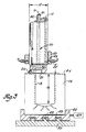
- a tubular housing 10 is employed for axial movement along axis 11 and throughout substantially the axial extent 12 of the interior of cavity 13 of the workpiece 14.
- the tubular housing 10 is constructed of tubular steel having a diameter 15 substantially the same but slightly less than the diameter of cavity 13 to be bored.
- the tubular housing should be in close-fitting tolerance to the walls of such cavity, preferably within a tolerance range of .008-.012 inches.
- the axially moveable tubular housing structure has its bottom end 10a floating on the spindle head 36 and its upper end (flanged upper portion 17) secured by the presence of a flange 18 on the spindle 23 (see Figure 6).
- the tubular housing is thus free to move axially with the spindle, but is fixed against rotary movement by pneumatic connections made at 90 or by other suitable fixing means.
- the spindle 23 is journaled in the tubular housing 10 for rotary movement therein and is also supported in a manner to permit conjoint axial movement of the tubular housing therewith; the spindle extends beyond the housing end 10a to carry a spindle head 36 not only for supporting the tubular housing, but for carrying a radially adjustable cutting tool 24.
- the spindle 23 is connected by a splined connection 25 at its upper end 23a to an armature 26 of a rotationally driving, high-speed brushless motor 27 (shown in Figure 2), the motor being supported on a plate 19; the electric motor receives its source of energy through suitable power connections at 28.
- the plate 19 is connected to a vertical brace 20 which in turn is secured to a connector plate 92 for vertical movement along a rail 93 by way of a dovetail or key slot connection (not shown).
- a conventional piston and cylinder actuator 22 is employed for moving the brace 20 and connector plate 21 along such rail via a ball screw assembly 94.
- the tubular housing 10, together with the rotationally driven spindle 23, is inserted into the cavity 13 by lowering plate 19 through actuator 22; the insertion rate is in the range of about 400-800 inches/minute.
- the cutting tool is radially positioned for rough boring by use of an adjustment means 30 which comprises an adjustment rod 31 which extends axially and concentrically through the center of the spindle 23 and extends through the motor 27 for connection to a screw drive actuator 32 having a motor 21.
- the actuator is supported, in turn, on a pair of plates 33 and 29 which are connected by member 16 to brace 20 also for vertical movement along rail 93; thus, actuator 32 is coupled to the plate 19 for conjoint movement in response to the elevation or de-elevation of spindle 23 and tubular housing 10.
- the independently axially moveable rod 31 is caused to selectively move downward on actuation of the screw drive in one rotational direction and caused to move upward or elevated in response to the reverse rotation of the screw drive.
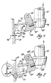
- the cutting tool is mounted on a pivot arm 34.
- the tool itself, has a preformed central opening 39 to act as a surface for fastening the cutting tool to a pin 49 on the pivot arm 34.
- the L-shaped pivot arm 34 pivots on a pivot pin or axis 35, which axis is secured to the side of the spindle head 36 (as shown in Figure 3) offset from the axis 11 of the spindle 23.
- the pivot arm 34 carries a radially actuatable contact surface 37 to permit the pivot arm to swing to and from the wall of cavity 13.
- Such surface 37 may be adjustable by use of a screw 95.
- the bottom end of the rod 31 carries a conical camming member 38 having a surface 48 mateable with the contact surface 37 of the pivot arm so that as the rod 31 is lowered within the tubular housing 10, the camming head 38 will contact surface 37 and move it radially outwardly.
- the cutting tool has a surface 40 which is positioned to have a side relief angle 41 great enough, such as in the range of 15-22 degrees, to provide for a heavy depth cut 42 and thereby perform a rough boring operation on the downward stroke of the tubular housing and spindle.
- This large side relief angle is promoted by an elevated position of the rod 31 with respect to the pivot arm.
- the tool In the position of the cutting tool of Figure 5, the tool has surface 40 positioned to have a side relief angle 41 of about 8-15 degrees, effective to promote finish boring on the upward stroke of tubular housing 10 and spindle 23.
- the depth of cut 84 is considerably smaller.
- an alternative radial adjusting means may be employed, as shown in Figure 7.
- the rod 31 is modified to have a camming head 38 redefined with separated camming surfaces 85, 86 and 87, but only camming surface 87 has an extended profile at 87a to move its pivot arm 34 a greater distance when the rod 31 is rotated (rather than elevated or deelevated).
- rotary camming to one angular extreme attains equal radial adjustment of all three arms 34 for rough boring, and movement to the other rotary extreme attains more radial adjustment for only one of the pivot arms to effect finish-machining with one cutting tool.
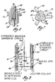
- adjustable fluidic bearings 44 which consist of orifices 45 located at several axial positions along the length of the tubular housing 10 (see Figure 8).
- Orifice 45 communicates between a hydrostatic fluid pressure supply 47 with the interior surface 10b of the tubular housing.
- an orifice may communicate such supply 47 with the exterior surface 10c of the tubular housing so that orifices 45 and such other orifice are diametrically opposed.
- Several orifices 45 are located equi-circumferentially about the inner surface of the tubular housing; they are located in pairs to promote equal and opposite fluid films on diametrically opposite sides of the spindle.
- Orifices 61 are also directed downwardly through tubular housing end 10a to provide a floating fluid film between the upper surface 62 of spindle head 36 and the housing.
- the hydrostatic fluid pressure supply is comprised of passages extending along the interior body of the tubular housing to connect at 43 with exterior pressure supply tubes.
- the guided orifice provides such a film of fluid between the spindle and tubular housing and/or the tubular housing and cavity wall.
- the fluid pressure supply is in the range of 20-40 psi and is adjustable to assure concentric alignment.
- a hydrostatic fluid pressure circuit 46 is employed.
- Such circuit has orifices 101, defined in the outer surface 10c of the tubular housing, at various circumferential locations thereof, but at different locations than the bearing orifices 45.
- the orifices 101 are located at a sufficient number of circumferential locations so that a desired fluid force will be properly directed from a selected orifice when the other orifices are not activated.
- Hydrostatic fluid pressure is injected for selected moments through one or more selected ones of these orifices 45 to impart a steering force. The steering force results from the reaction of the fluid pressure against a confronting surface to the orifice.
- a tubular collar 50 (as shown in Figure 2) is employed having a flat flanged portion 51 supported on a fixed annular seat 52 which, in turn, has an annular supporting flange 53 for carrying the bottom surface 54 of the collar flange 51.
- the flange 51 is held between the seat flange 53 and a supporting platform 55.
- the tubular housing may be steered by injection of hydrostatic pressurized fluid through circumferentially spaced pairs of diametrically opposed orifices 56,57 located in a bottom axial location of the collar 50 and orifices 58,59 in an upper axial location of seat 52.
- the tubular housing or collar may be caused to incrementally move for radial adjustment. Once the precise radial adjustment is achieved for the collar and the tubular housing within the collar, such interrelationship may be fixed by use of hydrostatic pressure deployed through ports 59 to clamp the upper surface 60 of the collar flange 51 against the platform 55.
- pairs of diametrically opposite gauging nozzles 62 may be employed within the tubular housing 10 at various axial locations different than that for the hydrostatic bearings, but desirably in or close to the spindle head.
- Hydrostatic fluid flow through the orifices 62 is restricted by the frontal positioning of the cylindrical wall of cavity 13. If the space between such walls 13 and the orifices 62 is closed or restricted, the back-pressure of the hydrostatic fluid flow is increased due to the restriction and thereby increases the fluid pressure communicated to the other opposed orifice 62.
- the hydrostatic fluidic pressure supply for the gauging is maintained in the pressure range of 12-44 psi.
- the pressure that is supplied to gauging nozzles 62 is sensed by either a straight or differential pressure transducer to determine the degree of back-pressure and thereby render an indication of the positioning of the tubular housing within the cavity.
- gauging nozzles may be employed to sense the positioning of the spindle 23 within the tubular housing 10.
- Pressure supply to orifices 62 may be provided by passages in the wall which communicate with a closed ring groove 105, such groove leading to an orifice 62. Slots 106 are added about the nozzles 62 to permit better escape of the fluid.
- Cooling fluid may be directed through the tubular housing to exit from a passage 81 for bathing the cutting tool. Cooling or cutting fluid may also be fed at 83 to be carried through a central passage 82 in the adjustment rod 31.
- the tubular housing 10, together with the rotationally driven spindle 23, is withdrawn from the cavity 13 along an upward stroke while the cutting tool 24 is repositioned for continuous finish boring of the cavity wall during such withdrawal.
- the repositioning of the cutting tool is illustrated in Figure 5, wherein rod 31 is raised by screw actuator 32 to permit pivot arm 34 to swing to the right, permitting the radially moveable surface 37 to move away from the cylindrical wall 13 thereby causing the surface 40 of the cutting tool to have a smaller side relief angle 41 characteristic of a finish-machining mode.
- the depth of cut of such finish-machining step is also reduced to about .045 inches.
- the tubular housing 10 and spindle 23 will be telescopically withdrawn into the collar 50 or fixed housing.
- the fixed housing is positioned closely adjacent the face 64 of the workpiece 14, preferably within a distance 65 of about 1.5-2.5 inches and commensurate with the height of the spindle head.
- the workpiece 14 is moved relatively transversely with respect to the axis of the spindle for carrying out milling while radially adjusting the cutting tool for milling of face 64.
- the workpiece may be moved on a support fixture 66 by an exterior actuator 67.
- Fixture 66 is guided by rails 68 a support 70 locked in key hole tracks 69 in the fixture support 70.
- the tubular housing 10 is guided and steered within the fixed housing 50 or collar to attain close milling tolerances.
- the pivot arm is moved to a satisfactory radial position so that the other surface 71 of the cutting tool insert is positioned to provide a side relief angle with respect to the face 64 of the milling block of a predetermined amount.
- the apparatus for stitch-machining the walls of an axially deep and narrow cylindrical cavity 13 of a workpiece 14 comprises: (a) a rotary driven spindle 23 of sufficient length to extend substantially throughout the axial extent 12 of the cavity, the spindle carrying a radially adjustable cutting tool 14 at its extremity; (b) a tubular housing support (10,19,20) for journaling the spindle 23, the tubular housing 10 being axially moveable for conjoint axial movement with the spindle and fixed against rotational movement; (c) means (47,45,46,13,23a) (56,57,58,59,50,53) for accurately guiding and steering the tubular housing support and spindle within the cavity; and (d) means (31,38,37,34,35) for radially adjusting the orientation of the cutting tool to effect different modes of machining with the tool.
Landscapes
- Engineering & Computer Science (AREA)
- Mechanical Engineering (AREA)
- Drilling And Boring (AREA)
- Cutting Tools, Boring Holders, And Turrets (AREA)
- Milling Processes (AREA)
Applications Claiming Priority (2)
| Application Number | Priority Date | Filing Date | Title |
|---|---|---|---|
| US07/137,772 US4847961A (en) | 1987-12-24 | 1987-12-24 | Method and apparatus for stitch-machining deep cavities in metal workpieces |
| US137772 | 1987-12-24 |
Publications (3)
| Publication Number | Publication Date |
|---|---|
| EP0323046A2 true EP0323046A2 (de) | 1989-07-05 |
| EP0323046A3 EP0323046A3 (en) | 1990-07-25 |
| EP0323046B1 EP0323046B1 (de) | 1993-08-11 |
Family
ID=22478986
Family Applications (1)
| Application Number | Title | Priority Date | Filing Date |
|---|---|---|---|
| EP88311427A Expired - Lifetime EP0323046B1 (de) | 1987-12-24 | 1988-12-02 | Methode und Gerät zum Bearbeiten von tiefen Löchern in Metallwerkstücken |
Country Status (8)
| Country | Link |
|---|---|
| US (1) | US4847961A (de) |
| EP (1) | EP0323046B1 (de) |
| JP (1) | JPH01205906A (de) |
| KR (1) | KR890009516A (de) |
| AU (1) | AU602841B2 (de) |
| CA (1) | CA1315967C (de) |
| DE (1) | DE3883193T2 (de) |
| MX (1) | MX168381B (de) |
Cited By (1)
| Publication number | Priority date | Publication date | Assignee | Title |
|---|---|---|---|---|
| WO2016146798A1 (de) * | 2015-03-17 | 2016-09-22 | Mauser-Werke Oberndorf Maschinenbau Gmbh | Feinbohrkopfsystem |
Families Citing this family (17)
| Publication number | Priority date | Publication date | Assignee | Title |
|---|---|---|---|---|
| GB2246089B (en) * | 1990-07-16 | 1994-01-12 | David Patrick Payne | Improvements in drills |
| US5419037A (en) * | 1994-05-20 | 1995-05-30 | Outboard Marine Corporation | Method of inserting, boring, and honing a cylinder bore liner |
| US6354772B1 (en) * | 1998-12-07 | 2002-03-12 | Paul W. Mueller | Cutting tool |
| WO2003099493A1 (en) * | 1999-12-20 | 2003-12-04 | Paul William Mueller | Cutting tool |
| WO2002049791A1 (en) * | 2000-12-18 | 2002-06-27 | Cardemon Inc., D/B/A Car-Tec Company | Adjustment method and apparatus for a boring tool |
| US7029209B2 (en) * | 2000-12-18 | 2006-04-18 | Cardemon, Inc. | Slidable boring tool with fine adjustment |
| US20050268759A1 (en) * | 2002-04-25 | 2005-12-08 | Cardemon Richard A | Slidable boring tool with fine adustment |
| JP5763363B2 (ja) * | 2011-02-18 | 2015-08-12 | 株式会社新機械技研 | ワークの穴加工装置及びワークの穴加工方法 |
| CN103192106B (zh) * | 2013-04-10 | 2016-06-22 | 肇庆本田金属有限公司 | 一种双向型活塞销孔的加工方法及加工刀具 |
| DE102013208027A1 (de) * | 2013-05-02 | 2014-11-06 | Artis Gmbh | Verfahren und vorrichtung zum einstellen auf eine motorspindel einer werkzeugmaschine aufgespannter einstellbarer werkzeuge |
| US10343224B2 (en) | 2016-04-04 | 2019-07-09 | Ford Motor Company | Interpolated milling tools and methods |
| CN106938349B (zh) * | 2017-04-21 | 2018-04-24 | 河北曲富木业有限公司 | 一种板材钻孔加工装置 |
| CN107378493A (zh) * | 2017-08-29 | 2017-11-24 | 南通纳侬精密机械有限公司 | 叶片端头数控切割铣钻复合自动机 |
| US20200282476A1 (en) * | 2017-11-14 | 2020-09-10 | Chetocorporation, S.A. | Device for machining internal channels and respective method of operation |
| CN110695631B (zh) * | 2019-12-08 | 2021-08-10 | 湖南凯斯机械股份有限公司 | 一种缝纫机机头的加工工艺 |
| CN112077357B (zh) * | 2020-09-17 | 2022-11-25 | 天路自动化(江苏)有限公司 | 模架在线自动化生产线 |
| CN119588976B (zh) * | 2024-11-28 | 2025-07-04 | 信一秀塔克机械(苏州)有限公司 | 一种用于阶梯孔加工的可调式镗削刀具 |
Family Cites Families (15)
| Publication number | Priority date | Publication date | Assignee | Title |
|---|---|---|---|---|
| US1562969A (en) * | 1922-12-01 | 1925-11-24 | Jordan Machine Tool Company | Reboring and grinding machine for engine cylinders |
| US1844316A (en) * | 1929-05-27 | 1932-02-09 | Simplicity Mfg Company | Boring and grinding machine |
| US2398362A (en) * | 1942-04-29 | 1946-04-16 | Ex Cell O Corp | Rotary cutterhead |
| DE859849C (de) * | 1943-02-28 | 1952-12-15 | Scheer & Cie C F | Werkzeug zum Bearbeiten von Auflageflaechen fuer Muttern u. dgl. |
| US3273423A (en) * | 1963-05-27 | 1966-09-20 | Donald B Rottler | Boring machine |
| US3438289A (en) * | 1967-06-08 | 1969-04-15 | Ingersoll Milling Machine Co | Boring machine with vibrationless boring bar |
| US3542528A (en) * | 1967-11-21 | 1970-11-24 | Jorgen Bech | End mill with variable cutting diameter |
| US4133089A (en) * | 1977-11-16 | 1979-01-09 | Wilhelm Hegenscheidt Gmbh | Combined precision boring and burnishing tool |
| IT1166100B (it) * | 1979-09-03 | 1987-04-29 | Ansaldo Spa | Alesatore per alberi cavi |
| US4307636A (en) * | 1980-03-31 | 1981-12-29 | Drillco Devices Limited | Undercutting tool |
| US4414869A (en) * | 1981-04-13 | 1983-11-15 | Augustine Paul M | Counterbore boring and refacing tool |
| US4436460A (en) * | 1981-06-11 | 1984-03-13 | Ex-Cell-O Corporation | Automatic depth compensating system |
| JPS5822282A (ja) * | 1981-08-04 | 1983-02-09 | 三菱電機株式会社 | エレベ−タの位置検出装置 |
| JPS60172B2 (ja) * | 1981-12-21 | 1985-01-07 | 東芝機械株式会社 | 立旋盤の主軸構造 |
| JPS62213901A (ja) * | 1986-03-13 | 1987-09-19 | Toshiba Corp | 複合バイト |
-
1987
- 1987-12-24 US US07/137,772 patent/US4847961A/en not_active Expired - Lifetime
-
1988
- 1988-10-13 KR KR1019880013464A patent/KR890009516A/ko not_active Withdrawn
- 1988-10-31 CA CA000581769A patent/CA1315967C/en not_active Expired - Fee Related
- 1988-12-02 DE DE88311427T patent/DE3883193T2/de not_active Expired - Lifetime
- 1988-12-02 EP EP88311427A patent/EP0323046B1/de not_active Expired - Lifetime
- 1988-12-20 MX MX014270A patent/MX168381B/es unknown
- 1988-12-22 JP JP63324694A patent/JPH01205906A/ja active Pending
- 1988-12-23 AU AU27503/88A patent/AU602841B2/en not_active Ceased
Cited By (1)
| Publication number | Priority date | Publication date | Assignee | Title |
|---|---|---|---|---|
| WO2016146798A1 (de) * | 2015-03-17 | 2016-09-22 | Mauser-Werke Oberndorf Maschinenbau Gmbh | Feinbohrkopfsystem |
Also Published As
| Publication number | Publication date |
|---|---|
| AU2750388A (en) | 1989-06-29 |
| AU602841B2 (en) | 1990-10-25 |
| DE3883193D1 (de) | 1993-09-16 |
| US4847961A (en) | 1989-07-18 |
| EP0323046A3 (en) | 1990-07-25 |
| CA1315967C (en) | 1993-04-13 |
| MX168381B (es) | 1993-05-20 |
| DE3883193T2 (de) | 1993-12-02 |
| KR890009516A (ko) | 1989-08-02 |
| EP0323046B1 (de) | 1993-08-11 |
| JPH01205906A (ja) | 1989-08-18 |
Similar Documents
| Publication | Publication Date | Title |
|---|---|---|
| US4847961A (en) | Method and apparatus for stitch-machining deep cavities in metal workpieces | |
| KR950001774B1 (ko) | 캘리퍼 가공 장치 및 방법과 캘리퍼 가공용 지그 | |
| EP0467372B1 (de) | Bearbeitungsvorrichtung für Ventilsitze | |
| US4613262A (en) | Drill motor assembly with gimbal normality and clamp-up capability | |
| US5544985A (en) | Deep bore drilling apparatus with rotatable single tube system | |
| CN108856744B (zh) | 一种带顶尖驱动调节装置的机床尾座 | |
| EP1499473B1 (de) | Konzentrische, pneumatisch/hydraulisch angetriebene vorschubeinrichtung | |
| EP1104343B1 (de) | Bohrlehre mit hydraulischem spannfutter und bohrerführung mit leitbohrung | |
| JP3371337B2 (ja) | 輪郭形状形成用回転切削装置 | |
| US4722123A (en) | Driving system for automatic lathes | |
| US3438288A (en) | Bearing support for tool spindles | |
| US4119388A (en) | Machine tool | |
| US4043695A (en) | Method of bottle boring | |
| CN215786851U (zh) | 一种锥形孔机筒的镗孔装置 | |
| CN218745019U (zh) | 锪窝装配工具 | |
| US4842450A (en) | Method and apparatus for self-adjusting boring bar | |
| KR920010567B1 (ko) | 회전 금속 절삭공구 | |
| EP0556226B1 (de) | Verbesserungen in beziehung zu werkzeugmaschinen | |
| JPH088054Y2 (ja) | 旋削加工機の切削剤供給装置 | |
| JPS6048284B2 (ja) | 工作機械のチャック装置 | |
| CN217142401U (zh) | 一种传动轴钻孔装置 | |
| JP3597340B2 (ja) | 工作機械の圧力ヘッド | |
| SU984709A1 (ru) | Устройство дл кольцевого сверлени | |
| JPH0217764Y2 (de) | ||
| KR100209487B1 (ko) | 수직형 머시닝 센터의 경사 테이블장치 |
Legal Events
| Date | Code | Title | Description |
|---|---|---|---|
| PUAI | Public reference made under article 153(3) epc to a published international application that has entered the european phase |
Free format text: ORIGINAL CODE: 0009012 |
|
| AK | Designated contracting states |
Kind code of ref document: A2 Designated state(s): DE FR GB |
|
| PUAL | Search report despatched |
Free format text: ORIGINAL CODE: 0009013 |
|
| AK | Designated contracting states |
Kind code of ref document: A3 Designated state(s): DE FR GB |
|
| 17P | Request for examination filed |
Effective date: 19901221 |
|
| 17Q | First examination report despatched |
Effective date: 19920430 |
|
| GRAA | (expected) grant |
Free format text: ORIGINAL CODE: 0009210 |
|
| AK | Designated contracting states |
Kind code of ref document: B1 Designated state(s): DE FR GB |
|
| REF | Corresponds to: |
Ref document number: 3883193 Country of ref document: DE Date of ref document: 19930916 |
|
| ET | Fr: translation filed | ||
| REG | Reference to a national code |
Ref country code: GB Ref legal event code: 746 Effective date: 19931124 |
|
| REG | Reference to a national code |
Ref country code: FR Ref legal event code: DL |
|
| PLBE | No opposition filed within time limit |
Free format text: ORIGINAL CODE: 0009261 |
|
| STAA | Information on the status of an ep patent application or granted ep patent |
Free format text: STATUS: NO OPPOSITION FILED WITHIN TIME LIMIT |
|
| 26N | No opposition filed | ||
| PGFP | Annual fee paid to national office [announced via postgrant information from national office to epo] |
Ref country code: DE Payment date: 19971021 Year of fee payment: 10 |
|
| PGFP | Annual fee paid to national office [announced via postgrant information from national office to epo] |
Ref country code: GB Payment date: 19971126 Year of fee payment: 10 |
|
| PGFP | Annual fee paid to national office [announced via postgrant information from national office to epo] |
Ref country code: FR Payment date: 19971215 Year of fee payment: 10 |
|
| PG25 | Lapsed in a contracting state [announced via postgrant information from national office to epo] |
Ref country code: DE Free format text: LAPSE BECAUSE OF THE APPLICANT RENOUNCES Effective date: 19981126 |
|
| PG25 | Lapsed in a contracting state [announced via postgrant information from national office to epo] |
Ref country code: GB Free format text: LAPSE BECAUSE OF NON-PAYMENT OF DUE FEES Effective date: 19981202 |
|
| GBPC | Gb: european patent ceased through non-payment of renewal fee |
Effective date: 19981202 |
|
| PG25 | Lapsed in a contracting state [announced via postgrant information from national office to epo] |
Ref country code: FR Free format text: LAPSE BECAUSE OF NON-PAYMENT OF DUE FEES Effective date: 19990831 |
|
| REG | Reference to a national code |
Ref country code: FR Ref legal event code: ST |