EP0321858A2 - Brenneinrichtung - Google Patents
Brenneinrichtung Download PDFInfo
- Publication number
- EP0321858A2 EP0321858A2 EP88120967A EP88120967A EP0321858A2 EP 0321858 A2 EP0321858 A2 EP 0321858A2 EP 88120967 A EP88120967 A EP 88120967A EP 88120967 A EP88120967 A EP 88120967A EP 0321858 A2 EP0321858 A2 EP 0321858A2
- Authority
- EP
- European Patent Office
- Prior art keywords
- combustion
- combustion chamber
- floor
- chimney
- burning
- Prior art date
- Legal status (The legal status is an assumption and is not a legal conclusion. Google has not performed a legal analysis and makes no representation as to the accuracy of the status listed.)
- Withdrawn
Links
- 238000002485 combustion reaction Methods 0.000 title claims abstract description 143
- 239000000446 fuel Substances 0.000 claims description 34
- 239000007789 gas Substances 0.000 claims description 21
- 238000010438 heat treatment Methods 0.000 claims description 21
- 238000001704 evaporation Methods 0.000 claims description 13
- 230000008020 evaporation Effects 0.000 claims description 13
- UGFAIRIUMAVXCW-UHFFFAOYSA-N Carbon monoxide Chemical compound [O+]#[C-] UGFAIRIUMAVXCW-UHFFFAOYSA-N 0.000 claims description 10
- 238000010304 firing Methods 0.000 claims description 10
- 239000003546 flue gas Substances 0.000 claims description 10
- 239000000523 sample Substances 0.000 claims description 8
- 239000007788 liquid Substances 0.000 claims description 3
- 230000005855 radiation Effects 0.000 claims description 3
- 239000000567 combustion gas Substances 0.000 description 4
- 238000010586 diagram Methods 0.000 description 4
- 239000000203 mixture Substances 0.000 description 4
- 238000011144 upstream manufacturing Methods 0.000 description 3
- 229910000831 Steel Inorganic materials 0.000 description 2
- 239000000956 alloy Substances 0.000 description 2
- 229910045601 alloy Inorganic materials 0.000 description 2
- VNNRSPGTAMTISX-UHFFFAOYSA-N chromium nickel Chemical compound [Cr].[Ni] VNNRSPGTAMTISX-UHFFFAOYSA-N 0.000 description 2
- 238000004939 coking Methods 0.000 description 2
- 230000001105 regulatory effect Effects 0.000 description 2
- 239000004071 soot Substances 0.000 description 2
- 239000010959 steel Substances 0.000 description 2
- RYGMFSIKBFXOCR-UHFFFAOYSA-N Copper Chemical compound [Cu] RYGMFSIKBFXOCR-UHFFFAOYSA-N 0.000 description 1
- 230000001133 acceleration Effects 0.000 description 1
- QVGXLLKOCUKJST-UHFFFAOYSA-N atomic oxygen Chemical compound [O] QVGXLLKOCUKJST-UHFFFAOYSA-N 0.000 description 1
- 238000000889 atomisation Methods 0.000 description 1
- 230000015572 biosynthetic process Effects 0.000 description 1
- 239000000571 coke Substances 0.000 description 1
- 238000001816 cooling Methods 0.000 description 1
- 229910052802 copper Inorganic materials 0.000 description 1
- 239000010949 copper Substances 0.000 description 1
- 238000005538 encapsulation Methods 0.000 description 1
- 238000010285 flame spraying Methods 0.000 description 1
- 230000007257 malfunction Effects 0.000 description 1
- 238000000034 method Methods 0.000 description 1
- 239000001301 oxygen Substances 0.000 description 1
- 229910052760 oxygen Inorganic materials 0.000 description 1
- 238000007747 plating Methods 0.000 description 1
- 230000001960 triggered effect Effects 0.000 description 1
Images

Classifications
-
- F—MECHANICAL ENGINEERING; LIGHTING; HEATING; WEAPONS; BLASTING
- F23—COMBUSTION APPARATUS; COMBUSTION PROCESSES
- F23N—REGULATING OR CONTROLLING COMBUSTION
- F23N1/00—Regulating fuel supply
- F23N1/02—Regulating fuel supply conjointly with air supply
- F23N1/022—Regulating fuel supply conjointly with air supply using electronic means
-
- F—MECHANICAL ENGINEERING; LIGHTING; HEATING; WEAPONS; BLASTING
- F23—COMBUSTION APPARATUS; COMBUSTION PROCESSES
- F23N—REGULATING OR CONTROLLING COMBUSTION
- F23N1/00—Regulating fuel supply
- F23N1/002—Regulating fuel supply using electronic means
-
- F—MECHANICAL ENGINEERING; LIGHTING; HEATING; WEAPONS; BLASTING
- F23—COMBUSTION APPARATUS; COMBUSTION PROCESSES
- F23N—REGULATING OR CONTROLLING COMBUSTION
- F23N2221/00—Pretreatment or prehandling
- F23N2221/04—Preheating liquid fuel
-
- F—MECHANICAL ENGINEERING; LIGHTING; HEATING; WEAPONS; BLASTING
- F23—COMBUSTION APPARATUS; COMBUSTION PROCESSES
- F23N—REGULATING OR CONTROLLING COMBUSTION
- F23N2225/00—Measuring
- F23N2225/02—Measuring filling height in burners
-
- F—MECHANICAL ENGINEERING; LIGHTING; HEATING; WEAPONS; BLASTING
- F23—COMBUSTION APPARATUS; COMBUSTION PROCESSES
- F23N—REGULATING OR CONTROLLING COMBUSTION
- F23N2225/00—Measuring
- F23N2225/04—Measuring pressure
-
- F—MECHANICAL ENGINEERING; LIGHTING; HEATING; WEAPONS; BLASTING
- F23—COMBUSTION APPARATUS; COMBUSTION PROCESSES
- F23N—REGULATING OR CONTROLLING COMBUSTION
- F23N2225/00—Measuring
- F23N2225/08—Measuring temperature
-
- F—MECHANICAL ENGINEERING; LIGHTING; HEATING; WEAPONS; BLASTING
- F23—COMBUSTION APPARATUS; COMBUSTION PROCESSES
- F23N—REGULATING OR CONTROLLING COMBUSTION
- F23N2225/00—Measuring
- F23N2225/08—Measuring temperature
- F23N2225/14—Ambient temperature around burners
-
- F—MECHANICAL ENGINEERING; LIGHTING; HEATING; WEAPONS; BLASTING
- F23—COMBUSTION APPARATUS; COMBUSTION PROCESSES
- F23N—REGULATING OR CONTROLLING COMBUSTION
- F23N2227/00—Ignition or checking
- F23N2227/38—Electrical resistance ignition
-
- F—MECHANICAL ENGINEERING; LIGHTING; HEATING; WEAPONS; BLASTING
- F23—COMBUSTION APPARATUS; COMBUSTION PROCESSES
- F23N—REGULATING OR CONTROLLING COMBUSTION
- F23N2229/00—Flame sensors
-
- F—MECHANICAL ENGINEERING; LIGHTING; HEATING; WEAPONS; BLASTING
- F23—COMBUSTION APPARATUS; COMBUSTION PROCESSES
- F23N—REGULATING OR CONTROLLING COMBUSTION
- F23N2235/00—Valves, nozzles or pumps
- F23N2235/12—Fuel valves
- F23N2235/14—Fuel valves electromagnetically operated
-
- F—MECHANICAL ENGINEERING; LIGHTING; HEATING; WEAPONS; BLASTING
- F23—COMBUSTION APPARATUS; COMBUSTION PROCESSES
- F23N—REGULATING OR CONTROLLING COMBUSTION
- F23N5/00—Systems for controlling combustion
- F23N5/003—Systems for controlling combustion using detectors sensitive to combustion gas properties
- F23N5/006—Systems for controlling combustion using detectors sensitive to combustion gas properties the detector being sensitive to oxygen
Definitions
- the invention relates to a combustion device according to the preamble of patent claim 1.
- Such combustion devices for liquid fuels which are used in particular in a heating system with an evaporation burner for the combustion of heating oil, have a combustion chamber and a heat exchanger for dissipating heat to a suitable heat transfer medium. With these burners, the fuel supply can only be reduced gradually.
- a control device which is provided with three relays which are triggered depending on the thermostat control.
- the relays are connected to two solenoids that operate a special oil regulator.
- a control device and an oil regulator are provided which can be operated in two stages. In the first stage of the oil regulator, only a small flow opening is opened. In this position of the oil regulator, the burner is operated when starting up or after reaching the desired room temperature. A large flow opening is opened in the second stage of the oil regulator. The oil regulator can be used in this position.
- the known burners of this type can be throttled only poorly in terms of their performance. The minimum output that can be achieved is approx. 25% of the Rated capacity. A further reduction is not possible because the risk of sooting is too high and the temperature falls below the dew point. The emission protection regulations cannot be complied with if the output is reduced further.
- the invention has for its object to design a burner of the type mentioned in such a way that a further power reduction is possible.
- no soot and no drop below the dew point should occur in both full and partial load operation.
- the fuel is supplied via a metering device which is infinitely variable.
- the fuel quantity can be metered precisely in all operating areas. This is particularly advantageous in part-load operation, since soot-free combustion can only be achieved with a precisely set fuel-air mixture. Since the power reduction in the new combustion device is not achieved by switching the burner off or on, but by throttling the fuel supply, cooling below the dew point can be prevented.
- the metering device is designed as a solenoid valve which can be controlled by pulses, the pulse duration being infinitely variable. Since the solenoid valve has a relatively large opening cross section, no blockages can occur. This is particularly advantageous for fuels with a higher viscosity.
- a main blower for conveying the combustion air is provided, the output of which can be controlled in a manner adapted to the amount of fuel. In this way, an optimal fuel-air mixture can be set so that soot-free combustion takes place.
- a glow plug which is used in a known manner in diesel engines, is arranged above the combustion chamber of the combustion device. In this way, the ignition of the fuel-air mixture can be achieved in a simple and inexpensive manner.
- a flue gas measuring probe arranged in the exhaust pipe determines a size of the flue gas which is characteristic of the combustion. In this way, compliance with the emission protection regulations can be monitored and the combustion process can be regulated.
- a controllable underfloor heating can be provided, which ensures an optimal evaporation temperature in all operating areas.
- the soot or coke formation can be prevented by preheating the fuel.
- the firing tray can advantageously be constructed in multiple layers, a layer with high thermal conductivity being arranged outside the firing chamber. As a result, a better heat distribution of the heat supplied via the floor heating is achieved, which is advantageous in the ignition process.
- the inner layer which is preferably made of high-alloy chromium-nickel steel, meets the requirements for strength.
- An oil level overflow sensor is arranged on the combustion chamber, which prevents the combustion chamber from overflowing with fuel.
- a control unit that monitors and controls the combustion process is assigned to the new combustion device. All sensors and all actuators are connected to the control unit. The simultaneous control of the fuel metering, the combustion chamber temperature and the combustion air supply can result in a significant reduction in output.
- an exhaust gas bypass duct is provided as a bypass to the heat exchanger.
- a controllable throttle valve is arranged in the exhaust gas bypass duct, whereby a direct, controlled supply of the combustion air into the chimney is achieved. This prevents the chimney from falling below the dew point.
- the combustion device formed with an evaporation burner has an air supply space which surrounds the combustion chamber and into which the main fan conveys the combustion air. Excessive pressure in the combustion chamber is prevented by throttle openings that are provided in the combustion chamber wall. In order to become independent of fluctuations in the chimney draft, the arrangement of an additional throttle in the flow direction behind the main fan can be advantageous.
- an air guiding body which is arranged in the air supply space.
- the air guide body guides the combustion air to the combustion chamber wall in such a way that heating takes place in counterflow to the exhaust gas.
- the combustion chamber (1) is delimited by the combustion chamber wall (2) and the combustion floor (3).
- the combustion gases emerging from the combustion chamber (1) give off their heat to a suitable heat transfer medium in a heat exchanger (21) which is arranged above the combustion chamber (1).
- the combustion gases enter the chimney via the exhaust pipe (30).
- the combustion device shown here is used in a heating system for the combustion of heating oil and other liquid fuels.
- the invention is not restricted to a specific type of burner.
- the combustion device according to the invention can be designed, for example, with an evaporation burner or an atomization burner.
- the fuel is supplied via a fuel line (15) which connects a tank (not shown in the drawing) and the combustion chamber (1).
- the solenoid valve (14) is arranged in the fuel line (15) and can be controlled by pulses for metering the smallest amounts of fuel. The pulse duration can be regulated continuously. This metering device enables the burner device to be operated at a greatly reduced output. Due to the infinitely variable regulation of the solenoid valve (14), only the desired one arrives Amount of fuel in the combustion chamber (1). In this way, optimal combustion conditions can be set, which minimizes the risk of sooting or coking. Since the opening cross section of the solenoid valve (14) is relatively large, blockage does not occur even with fuels with increased viscosity.
- a safety solenoid valve (13) is connected upstream of the solenoid valve (14), which prevents further fuel supply, in particular in the event of malfunctions.
- the fuel leaves the fuel line (15) at the level of the firing tray (3).
- an oil level overflow sensor (12) is provided.
- the oil level overflow sensor (12) can be designed as an NTC resistor which is arranged in a riser pipe (38) which is connected to the fuel line (15). It is also possible that the NTC resistor is attached directly to the combustion chamber (1).
- the firing tray is first preheated.
- An adjustable floor heating (9) is provided below the firing floor (3).
- a floor temperature sensor (10) is assigned to the control loop of the floor heating (9).
- the floor heating (9) ensures that the fuel is sufficiently ignitable.
- the floor temperature should be around 360 ° C. In order to achieve good combustion over the entire load range, it may be necessary to switch on the floor heating.
- the firing tray (3) has a multilayer structure, a first layer with high thermal conductivity, for example copper, being provided outside the firing chamber (1). As a result, the heat supplied via the floor heating is distributed evenly.
- the required strength requirements are met by a second layer, which is provided inside the combustion chamber (1) and is made of high-alloy chromium-nickel steel.
- the firing tray (3) can be produced by plating or flame spraying the first layer onto the second layer.
- the combustion air is drawn in via the controllable main fan (16) into a cylindrical air supply space (4) which surrounds the combustion space (1).
- the combustion air flows into the combustion chamber (1) via throttle openings (36) which are provided in the combustion chamber wall (2).
- throttle openings (36) which are provided in the combustion chamber wall (2).
- solenoid valve (14) In the start-up phase, only a few drops of oil are supplied via the solenoid valve (14).
- the fuel-air mixture is ignited with a glow plug (11), which is arranged above the combustion floor (3) on the combustion chamber wall (2). Glow plugs of this type are used in a known manner in diesel engines. Compared to other ignition devices, the glow plug (11) is characterized by the simple structure and the low acquisition costs. Encapsulation of the filament ensures a long service life of the glow plug.
- a flame monitor (17) is installed at the level of the exhaust gas outlet from the combustion chamber. If the flame breaks off, the flame monitor (17) interrupts the fuel supply.
- the combustion exhaust gases flow from the combustion chamber (1) to the heat exchanger (21). With the release of heat to a suitable heat transfer medium, the combustion exhaust gases get into the exhaust pipe (30) and finally into the chimney, which is not shown in the drawing.
- a flue gas measuring probe (29) is arranged in the exhaust pipe (30) and can be used to determine a characteristic size of the flue gas.
- the flue gas measuring probe (29) can be a lambda probe, for example, which determines the oxygen concentration of the flue gas. It can be used to determine whether there is good and residue-free combustion of the fuel in the combustion chamber (1) he follows. The combustion process is monitored and controlled by the control unit (31).
- the control unit (31) is connected to all measuring and control elements of the combustion device.
- An outside temperature sensor (33), a room thermostat (34), the floor temperature sensor (10), the oil level overflow sensor (12), the flame monitor (17), the pressure monitor (35) and the flue gas measuring probe (29) are provided as measuring elements ) controls the actuators of the burner.
- a control of the solenoid valve (14), the floor heating (9) and the main fan (16) is provided in the combustion device according to the invention. Sooting or coking of the combustion device can be prevented. At the same time, compliance with the emission protection regulations is guaranteed.
- FIG. 2 shows a schematic circuit diagram of the control unit (31).
- the measured values determined by the measuring elements (10, 12, 17, 29, 33, 34, 35) are digitized and fed to a microprocessor-controlled map control unit (37). If the measured value does not correspond to the target value, the actuators (9, 11, 13, 14, 16) are activated.
- the evaporation burner (39) like the burner described in FIG. 1, has a combustion chamber (1) and a heat exchanger (21).
- An exhaust gas bypass duct (22) is provided as a bypass to the heat exchanger (21), in which a controllable throttle valve (23) is arranged.
- the main exhaust gas flow (19) emerging from the combustion chamber (1) thus only partially reaches the heat exchanger (21).
- An exhaust gas bypass flow (20) is led directly into the exhaust pipe (30) via the exhaust gas bypass flow duct (22). Through the Direct supply of warm combustion gases can prevent the temperature from falling below the dew point in the flue pipe and in the chimney.
- a chimney temperature sensor (28) is arranged on the exhaust pipe (30) as a measuring element.
- a controllable additional fan (25) is provided above the heat exchanger (21) and can be activated if the draft is too low. It is controlled together with the main fan (16), which is arranged in the area of the combustion chamber (1).
- An adjustable chimney throttle (26) is attached to the exhaust pipe (30) in the exhaust gas direction behind the additional fan (25). This can compensate for fluctuations in differential pressure in the chimney.
- the arrangement of a further throttle, which is not shown in the drawing, in the flow direction of the combustion air behind the main fan (16) ensures pressure conditions in the combustion chamber (1) which are almost independent of the chimney draft.
- a chimney pressure sensor (27) is provided on the exhaust pipe (30) as a measuring element for the chimney draft. It is also possible to arrange the chimney pressure sensor (27) in the area of the main fan (16). The pressure conditions in the combustion chamber (1) are monitored with the combustion chamber pressure sensor (24), which is arranged upstream of the additional fan (25) in the exhaust gas direction.
- the floor temperature sensor (10) in the area of the combustion floor (3), the flame monitor (17) in the area where the combustion exhaust gas emerges from the combustion chamber (1) and the oil level overflow sensor (12) on the riser (38) of the fuel line (15) arranged.
- a glow plug (11) is attached to the combustion chamber wall (2) above the combustion floor (3) and projects into the combustion chamber (1).
- the evaporation burner (39) is combined with a control unit (31 '), which is based on the control unit (31) according to FIGS. 1 and 2.
- the control unit (31 ') is connected to all measuring and actuating elements of the combustion device according to FIG. 3.
- the measuring elements are the outside temperature sensor (33), the room thermostat (34), the floor temperature sensor (10), the flame monitor (17), the oil level overflow sensor (12), the pressure monitor (35), the combustion gas temperature sensor (18), the combustion chamber pressure sensor (24) , the chimney pressure sensor (27), the chimney temperature sensor (28) and the flue gas measuring probe (29) are provided.
- the control unit (31 ') controls the combustion process via the solenoid valve (14), the safety solenoid valve (13), the floor heating (9), the glow plug (11), the main blower (16), the auxiliary blower (25), the throttle valve (23 ) and the chimney throttle (26).
- a microprocessor-controlled map control unit is provided in the control unit (31 ').
- the evaporation burner (39) according to FIG. 3 is shown enlarged.
- the outside of the combustion chamber (1) is surrounded by an air supply chamber (4).
- An air guide (5) is arranged in the air supply space (4) and surrounds the combustion chamber wall (2) like a pot. At its free, upward-facing edge, the air guiding body (5) slopes towards the combustion chamber wall (2).
- the combustion air is drawn in from the environment via the main fan (16) into the air supply space (4).
- the air guide (5) guides the combustion air to its free edge, which serves as a deflecting edge for the air flow.
- the combustion air is guided through the air baffle (5) after the deflection on the combustion chamber wall (2), whereby heating takes place in counterflow to the exhaust gas.
- the annular space between the combustion chamber wall (2) and air guide body (5) tapers to an annular gap (7). The resulting acceleration of the flow leads to an improvement in the heat transfer.
- the air distribution space (6) which serves to supply combustion air into the interior of the burner, is limited by the combustion chamber wall (2) and the air guide (5).
- the glow plug (11) is also possible to attach the glow plug (11) to the air guide (5), which then also serves as a heat sink.
- the air distribution space (6) has an expanding cross section.
- the combustion air flowing in via the annular gap (7) therefore experiences a delay in the air distribution space (6), which favors the supply to the combustion space.
- the combustion air enters the combustion chamber (1) via throttle openings (not shown in the drawing) which are provided in the combustion chamber wall (2). Preheating the combustion air further improves the combustion process, in particular in part-load operation, and relieves the floor heating (9).
- the outer shape of the combustion chamber wall (2) corresponds to the outer surface of three opening truncated cones, which are arranged one above the other and whose outer diameter increases in the direction of the main exhaust gas flow (19).
- This design of the combustion chamber (1) achieves good and residue-free combustion even with a small flame.
- the combustion chamber wall (2) is designed to converge in the area of the exit of the main exhaust gas flow (19) from the combustion chamber (1).
- Radiation converters (8) protrude into the combustion chamber (1) and are arranged almost vertically to the combustion chamber wall (2). The radiation converters (8) are correctively heated up and radiate their heat in the direction of the firing tray (3). Good evaporation of the fuel is thereby achieved.
Landscapes
- Engineering & Computer Science (AREA)
- Chemical & Material Sciences (AREA)
- Combustion & Propulsion (AREA)
- Mechanical Engineering (AREA)
- General Engineering & Computer Science (AREA)
- Control Of Combustion (AREA)
- Regulation And Control Of Combustion (AREA)
- Feeding And Controlling Fuel (AREA)
Abstract
Description
- Die Erfindung betrifft eine Brenneinrichtung nach dem Oberbegriff des Patentanspruches 1.
- Derartige Brenneinrichtungen für flüssige Brennstoffe, die insbesondere in einer Heizungsanlage mit einem Verdampfungsbrenner zur Verbrennung von Heizöl zum Einsatz kommen, besitzen einen Brennraum und einen Wärmeaustauscher zur Wärmeabgabe an ein geeignetes Wärmeträgermedium. Bei diesen Brenneinrichtungen kann die Brennstoffzufuhr nur stufenweise gedrosselt werden.
- Bei bekannten Brenneinrichtungen dieser Art ist ein Steuergerät vorgesehen, das mit drei Relais versehen ist, die abhängig von der Thermostatsteuerung ausgelöst werden. Die Relais sind mit zwei Hubmagneten verbunden, die einen besonderen Ölregler betätigen.
- Bei einer anderen bekannten Brenneinrichtung dieser Art (DE-OS 27 55 621) ist ein Steuergerät und ein Ölregler vorgesehen, der auf zwei Stufen betrieben werden kann. In der ersten Stufe des Ölreglers wird nur eine kleine Durchflußöffnung freigegeben. In dieser Stellung des Ölreglers wird die Brenneinrichtung beim Anfahren oder nach dem Erreichen der gewünschten Raumtemperatur betrieben. In der zweiten Stufe des Ölreglers wird eine große Durchflußöffnung freigegeben. In dieser Stellung ist der Ölregler einsetzbar. Die bekannten Brenneinrichtungen dieser Art können bezüglich ihrer Leistung aber nur schlecht gedrosselt werden. Die erreichbare Minimalleistung liegt bei ca. 25 % der Nennleistung. Eine weitere Reduzierung ist nicht möglich, da die Verrußungsgefahr zu hoch ist und außerdem Taupunktsunterschreitungen auftreten. Auch können die Emissionsschutzbestimmungen bei weiter reduzierter Leistung nicht eingehalten werden.
- Der Erfindung liegt die Aufgabe zugrunde, eine Brenneinrichtung der eingangs genannten Art so auszubilden, daß eine weitere Leistungsreduzierung möglich ist. Sowohl im Voll- als auch im Teillastbetrieb soll bei der neuen Brenneinrichtung keine Verrußung und keine Taupunktsunterschreitung auftreten.
- Diese Aufgabe wird bei einer Brenneinrichtung der eingangs genannten Art durch die kennzeichnenden Merkmale des Anspruches 1 gelöst. Bei der erfindungsgemäßen Brenneinrichtung erfolgt die Brennstoffzufuhr über eine Dosiereinrichtung, die stufenlos regelbar ist. Hierdurch kann in allen Betriebsbereichen eine genaue Dosierung der Brennstoffmenge erfolgen. Dies ist insbesondere im Teillastbetrieb vorteilhaft, da eine rußfreie Verbrennung nur bei einem genau eingestellten Brennstoff-Luftgemisch erreicht werden kann. Da die Leistungsreduzierung bei der neuen Brenneinrichtung nicht durch Ab- bzw. Anschalten des Brenners erreicht wird, sondern durch Drosselung der Brennstoffzufuhr, kann ein Abkühlen unter den Taupunkt verhindert werden.
- Weitere Vorteile und Merkmale der Erfindung ergeben sich aus den Unteransprüchen.
- In einer vorteilhaften Ausführungsform ist die Dosiereinrichtung als Magnetventil ausgebildet, das durch Impulse ansteuerbar ist, wobei die Impulsdauer stufenlos geregelt werden kann. Da bei dem Magnetventil ein relativ großer Öffnungsquerschnitt vorliegt, können keine Verstopfungen auftreten. Dies ist insbesondere bei Brennstoffen mit höherer Viskosität vorteilhaft.
- Bei der neuen Brenneinrichtung ist ein Hauptgebläse zur Förderung der Verbrennungsluft vorgesehen, das in seiner Förderleistung an die Brennstoffmenge angepaßt steuerbar ist. Hierdurch kann ein optimales Brennstoff-Luftgemisch eingestellt werden, so daß eine rußfreie Verbrennung erfolgt.
- Oberhalb des Brennbodens der Brenneinrichtung ist eine Glühkerze, die bei Dieselmotoren in bekannter Weise eingesetzt wird, angeordnet. Hiermit kann auf einfache und kostengünstige Weise die Zündung des Brennstoff-Luftgemisches erreicht werden.
- Eine im Abgasrohr angeordnete Rauchgasmeßsonde bestimmt eine für die Verbrennung charakteristische Größe des Rauchgases. Hierdurch kann die Einhaltung der Emissionsschutzvorschriften überwacht und der Verbrennungsvorgang geregelt werden.
- Bei der erfindungsgemäßen Brenneinrichtung kann in einer vorteilhaften Ausführungsform eine regelbare Bodenheizung vorgesehen sein, die in allen Betriebsbereichen eine optimale Verdampfungstemperatur gewährleistet. Insbesondere beim Anfahren der Brenneinrichtung kann die Ruß- bzw. Koksbildung durch eine Vorwärmung des Brennstoffes verhindert werden.
- Der Brennboden kann vorteilhafterweise mehrschichtig aufgebaut sein, wobei außerhalb des Brennraumes eine Schicht mit hoher Wärmeleitfähigkeit angeordnet ist. Hierdurch wird eine bessere Wärmeverteilung der über die Bodenheizung zugeführten Wärme erzielt, was beim Zündvorgang vorteilhaft ist. Die innenliegende Schicht, die vorzugsweise aus einem hochlegierten Chromnickelstahl hergestellt ist, erfüllt die Anforderungen an die Festigkeit.
- Am Brennraum ist ein Ölstandsüberlaufsensor angeordnet, der ein Vollaufen des Brennraumes mit Brennstoff verhindert.
- Der neuen Brenneinrichtung ist eine Regelungseinheit zugeordnet, die den Verbrennungsvorgang überwacht und regelt. Sämtliche Meßwertaufnehmer und alle Stellglieder sind mit der Regelungseinheit verbunden. Durch die gleichzeitige Regelung der Brennstoffdosierung, der Brennbodentemperatur und der Verbrennungsluftzufuhr kann eine starke Leistungsreduzierung erzielt werden.
- In einer weiteren vorteilhaften Ausführungsform ist ein Abgasnebenstromkanal als Bypass zum Wärmeaustauscher vorgesehen. In dem Abgasnebenstromkanal ist eine regelbare Drosselklappe angeordnet, wodurch eine direkte, geregelte Zuführung der Verbrennungsluft in den Kamin erreicht wird. Hierdurch können Taupunktsunterschreitungen im Kamin verhindert werden.
- Die mit einem Verdampfungsbrenner ausgebildete Brenneinrichtung besitzt einen Luftzuführraum, der den Brennraum umgibt und in den das Hauptgebläse die Verbrennungsluft fördert. Ein zu hoher Druck im Brennraum wird durch Drosselöffnungen verhindert, die in der Brennraumwand vorgesehen sind. Um von Schwankungen des Kaminzuges unabhängig zu werden, kann die Anordnung einer zusätzlichen Drossel in Strömungsrichtung hinter dem Hauptgebläse vorteilhaft sein.
- In einer weiteren vorteilhaften Ausführungsform wird ein Luftleitkörper vorgeschlagen, der in dem Luftzuführraum angeordnet ist. Der Luftleitkörper führt die Verbrennungsluft so an die Brennraumwand, daß eine Erwärmung im Gegenstrom zum Abgas erfolgt. Hierdurch kann insbesondere in der Anfahrphase die Zündwilligkeit des Brennstoffes erhöht werden.
- Weitere vorteilhafte Merkmale der Erfindung ergeben sich aus den Ausführungsbeispielen, die in der Zeichnung dargestellt sind und in der nachfolgenden Beschreibung erläutert werden.
- Es zeigen:
- Fig. 1 ein schematisches Schaltbild einer Ausführungsform der neuen Brenneinrichtung,
- Fig. 2 ein schematisches Schaltbild der Regelungseinheit aus Fig. 1,
- Fig. 3 ein schematisches Schaltbild einer weiteren Ausführungsform der neuen Brenneinrichtung mit einem Verdampfungsbrenner,
- Fig. 4 eine schematische, vergrößerte Darstellung des Verdampfungsbrenners aus Fig. 3.
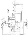
- Bei der in Fig.1 dargestellten Brenneinrichtung wird der Brennraum (1) durch die Brennraumwand (2) und den Brennboden (3) begrenzt. Die aus dem Brennraum (1) austretenden Verbrennungsgase geben in einem Wärmeaustauscher (21), der oberhalb des Brennraumes (1) angeordnet ist, ihre Wärme an ein geeignetes Wärmeträgermedium ab. Über das Abgasrohr (30) gelangen die Verbrennungsgase in den Kamin.Die hier schematisch dargestellte Brenneinrichtung wird in einer Heizungsanlage zur Verbrennung von Heizöl und anderen flüssigen Brennstoffen eingesetzt. Die Erfindung ist nicht auf einen bestimmten Brennertyp beschränkt. Die erfindungsgemäße Brenneinrichtung kann beispielsweise mit einem Verdampfungsbrenner oder einem Zerstäubungsbrenner ausgebildet sein.
- Die Brennstoffzufuhr erfolgt über eine Brennstoffleitung (15), die einen in der Zeichnung nicht dargestellten Tank und den Brennraum (1) miteinander verbindet. In der Brennstoffleitung (15) ist das Magnetventil (14) angeordnet, das zur Dosierung geringster Brennstoffmengen durch Impulse ansteuerbar ist. Hierbei kann die Impulsdauer stufenlos geregelt werden. Mit dieser Dosiereinrichtung ist ein Betrieb der Brenneinrichtung bei stark reduzierter Leistung möglich. Durch die stufenlose Regelung des Magnetventils (14) gelangt nur die gewünschte Brennstoffmenge in den Brennraum (1). Hierdurch können optimale Verbrennungsverhältnisse eingestellt werden, wodurch die Gefahr der Verrußung bzw.Verkokung minimiert ist. Da der Öffnungsquerschnitt des Magnetventils (14) relativ groß ist, tritt selbst bei Brennstoffen mit erhöhter Viskosität eine Verstopfung nicht auf.
- Dem Magnetventil (14) ist ein Sicherheitsmagnetventil (13) vorgeschaltet, das insbesondere bei Betriebsstörungen eine weitere Brennstoffzuführung unterbindet. Weiterhin liegt in der Brennstoffleitung (15) ein Druckwächter (35), der einen konstanten Vordruck am Magnetventil (14) gewährleistet. Der Brennstoff verläßt die Brennstoffleitung (15) in Höhe des Brennbodens (3). Um ein Vollaufen des Brennraumes (1) mit Brennstoff zu verhindern, ist ein Ölstandsüberlaufsensor (12) vorgesehen. Der Ölstandsüberlaufsensor (12) kann als NTC-Widerstand ausgebildet sein, der in einem Steigrohr (38) angeordnet ist, das mit der Brennstoffleitung (15) in Verbindung steht. Es ist auch möglich, daß der NTC-Widerstand direkt am Brennraum (1) angebracht ist.
- Zum Anfahren der Brenneinrichtung wird zunächst der Brennboden vorgeheizt. Unterhalb des Brennbodens (3) ist eine regelbare Bodenheizung (9) vorgesehen. Dem Regelkreis der Bodenheizung (9) ist ein Bodentemperaturfühler (10) zugeordnet. In der Anfahrphase gewährleistet die Bodenheizung (9) eine ausreichende Zündwilligkeit des Brennstoffes. Für leichtes Heizöl sollte die Bodentemperatur bei ca.360°C liegen. Um über den gesamten Lastbereich eine gute Verbrennung zu erzielen, kann die Zuschaltung der Bodenheizung erforderlich sein.
- Der Brennboden (3) ist mehrschichtig aufgebaut, wobei außerhalb des Brennraumes (1) eine erste Schicht mit hoher Wärmeleitfähigkeit, beispielsweise Kupfer, vorgesehen ist. Hierdurch wird die über die Bodenheizung zugeführte Wärme gleichmäßig verteilt.
- Die erforderlichen festigkeitstechnischen Anforderungen werden durch eine zweite Schicht erfüllt, die innerhalb des Brennraums (1) vorgesehen ist.Diese besteht aus hochlegiertem Chromnickelstahl. Die Herstellung des Brennbodens (3) kann durch Platierung oder Flammenspritzen der ersten Schicht auf die zweite Schicht erfolgen.
- Die Verbrennungsluft wird über das regelbare Hauptgebläse (16) in einen zylinderförmigen Luftzuführraum (4) gesaugt, der den Brennraum (1) umgibt. Die Verbrennungsluft strömt über Drosselöffnungen (36), die in der Brennraumwand (2) vorgesehen sind, in den Brennraum (1). In der Anfahrphase werden nur wenige Öltropfen über das Magnetventil (14) zugeführt. Die Zündung des Brennstoff-Luftgemisches erfolgt mit einer Glühkerze (11), die oberhalb des Brennbodens (3) an der Brennraumwand (2) angeordnet ist. Derartige Glühkerzen kommen in bekannter Weise bei Dieselmotoren zum Einsatz. Gegenüber anderen Zündeinrichtungen zeichnet sich die Glühkerze (11) durch den einfachen Aufbau und die niedrigen Anschaffungskosten aus. Eine Kapselung der Glühwendel gewährleistet eine hohe Standzeit der Glühkerze.
- In Höhe des Abgasaustrittes aus dem Brennraum ist ein Flammenwächter (17) angebracht. Bei Flammenabriß bewirkt der Flammenwächter (17) eine Unterbrechung der Brennstoffzufuhr. Die Verbrennungsabgase strömen aus dem Brennraum (1) zu dem Wärmeaustauscher (21). Unter Wärmeabgabe an ein geeignetes Wärmeträgermedium gelangen die Verbrennungsabgase in das Abgasrohr (30) und schließlich in den Kamin, der in der Zeichnung nicht dargestellt ist.
- Im Abgasrohr (30) ist eine Rauchgasmeßsonde (29) angeordnet, mit der eine charakteristische Größe des Rauchgases bestimmt werden kann. Die Rauchgasmeßsonde (29) kann beispielsweise eine Lambda-Sonde sein, die die Sauerstoffkonzentration des Rauchgases bestimmt. Hiermit kann ermittelt werden, ob im Brennraum (1) eine gute und rückstandsfreie Verbrennung des Brennstoffes erfolgt. Die Überwachung und Regelung des Verbrennungsvorganges erfolgt über die Regelungseinheit (31).
- Die Regelungseinheit (31) ist mit allen Meß- und Stellgliedern der Brenneinrichtung verbunden. Als Meßglieder sind ein Außentemperaturfühler (33), ein Raumthermostat (34), der Bodentemperaturfühler (10), der Ölstandsüberlaufsensor (12), der Flammenwächter (17), der Druckwächter (35) und die Rauchgasmeßsonde (29) vorgesehen.Die Regelungseinheit (31) regelt die Stellglieder der Brenneinrichtung. Um in allen Betriebsbereichen stöchiometrische Verbrennungsverhältnisse zu gewährleisten, ist bei der erfindungsgemäßen Brenneinrichtung eine Regelung des Magnetventiles (14), der Bodenheizung (9) und des Hauptgebläses (16) vorgesehen. Somit kann eine Verrußung oder Verkokung der Brenneinrichtung verhindert werden. Gleichzeitig ist die Einhaltung der Emissionsschutzvorschriften gewährleistet.
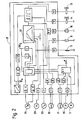
- In Fig. 2 ist ein schematisches Schaltbild der Regelungseinheit (31) dargestellt. Die von den Meßgliedern (10, 12, 17, 29, 33, 34, 35) ermittelten Meßwerte werden digitalisiert und einer mikroprozessorgesteuerten Kennfeldsteuerungseinheit (37) zugeführt. Entspricht der Meßwert nicht dem Sollwert, so werden die Stellglieder (9, 11, 13, 14, 16) angesteuert.
- In Fig. 3 ist eine weitere vorteilhafte Ausführungsform der Brenneinrichtung dargestellt, die mit einem Verdampfungsbrenner 39) ausgebildet ist. Die in der Fig. 1 eingeführten Bezugszeichen werden nachfolgend entsprechend verwendet. Der Verdampfungsbrenner (39) besitzt ebenso wie der in Fig. 1 beschriebene Brenner einen Brennraum (1) und einen Wärmeaustauscher (21). Als Bypass zum Wärmeaustauscher (21) ist ein Abgasnebenstromkanal (22) vorgesehen, in dem eine regelbare Drosselklappe (23) angeordnet ist. Der aus dem Brennraum (1) austretende Abgashauptstrom (19) gelangt somit nur teilweise an den Wärmeaustauscher (21). Ein Abgasnebenstrom (20) wird über den Abgasnebenstromkanal (22) direkt in das Abgasrohr (30) geführt. Durch die direkte Zuführung von warmen Verbrennungsgasen können Taupunktunterschreitungen im Abgasrohr und im Kamin verhindert werden. Hierfür ist als Meßglied ein Kamintemperaturfühler (28) am Abgasrohr (30) angeordnet. Oberhalb des Wärmeaustauschers (21) ist ein regelbares Zusatzgebläse (25) vorgesehen, das bei zu geringem Zug zugeschaltet werden kann. Es wird gemeinsam mit dem Hauptgebläse (16) geregelt, das im Bereich des Brennraumes (1) angeordnet ist. In Abgasrichtung hinter dem Zusatzgebläse (25) ist am Abgasrohr (30) eine regelbare Kamindrossel (26) befestigt. Hiermit können Differenzdruckschwankungen im Kamin ausgeglichen werden. Die Anordnung einer weiteren Drossel, die in der Zeichnung nicht dargestellt ist, in Strömungsrichtung der Verbrennungsluft hinter dem Hauptgebläse (16), gewährleistet vom Kaminzug nahezu unabhängige Druckverhältnisse im Brennraum (1). Als Meßglied für den Kaminzug ist ein Kamindrucksensor (27) am Abgasrohr (30) vorgesehen. Es ist auch möglich, den Kamindrucksensor (27) im Bereich des Hauptgebläses (16) anzuordnen. Die Druckverhältnisse im Brennraum (1) werden mit dem Brennraumdrucksensor (24) überwacht, der in Abgasrichtung vor dem Zusatzgebläse (25) angeordnet ist.
- Am Brennraum (1) des Verdampfungsbrenners (39) ist der Bodentemperaturfühler (10) im Bereich des Brennbodens (3), der Flammenwächter (17) im Bereich des Austrittes des Verbrennungsabgases aus dem Brennraum (1) und der Ölstandsüberlaufsensor (12) an der Steigleitung (38) der Brennstoffleitung (15) angeordnet. Eine Glühkerze (11) ist oberhalb des Brennbodens (3) an der Brennraumwand (2) befestigt und ragt in den Brennraum (1).
- Der Verdampfungsbrenner (39) ist mit einer Regelungseinheit (31′) kombiniert, die auf der Regelungseinheit (31) gemäß der Fig. 1 und 2 aufbaut. Die Regelungseinheit (31′) ist mit sämtlichen Meß- und Stellgliedern der Brenneinrichtung gemäß Fig. 3 verbunden.
- Als Meßglieder sind der Außentemperaturfühler (33), der Raumthermostat (34), der Bodentemperaturfühler (10), der Flammenwächter (17), der Ölstandsüberlaufsensor (12), der Druckwächter (35), der Brennabgastemperaturfühler (18), der Brennraumdrucksensor (24), der Kamindrucksensor (27), der Kamintemperaturfühler (28) und die Rauchgasmeßsonde (29) vorgesehen. Die Regelungseinheit (31′) regelt den Verbrennungsvorgang über das Magnetventil (14), das Sicherheitsmagnetventil (13), die Bodenheizung (9), die Glühkerze (11), das Hauptgebläse (16), das Zusatzgebläse (25), die Drosselklappe (23) und die Kamindrosselklappe (26). Hierbei ist eine mikroprozessorgesteuerte Kennfeldsteuerungseinheit in der Regelungseinheit (31′) vorgesehen.
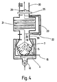
- In Fig. 4 ist der Verdampfungsbrenner (39) gemäß Fig. 3 vergrößert dargestellt. Die Außenseite des Brennraumes (1) wird von einem Luftzuführraum (4) umgeben. In dem Luftzuführraum (4) ist ein Luftleitkörper (5) angeordnet, der die Brennraumwand (2) topfartig umgibt. An seinem freien nach oben weisenden Rand neigt sich der Luftleitkörper (5) zur Brennraumwand (2) hin.
- Die Verbrennungsluft wird aus der Umgebung über das Hauptgebläse (16) in den Luftzuführraum (4) angesaugt. Der Luftleitkörper (5) führt die Verbrennungsluft zu seinem freien Rand, der als Umlenkkante für die Luftströmung dient. Die Verbrennungsluft wird durch den Luftleitkörper (5) nach der Umlenkung an der Brennraumwand (2) geführt, wodurch eine Erwärmung im Gegenstrom zum Abgas erfolgt. Der Ringraum zwischen Brennraumwand (2) und Luftleitkörper (5) verjüngt sich bis zu einem Ringspalt (7). Die daduch erreicht Beschleunigung der Strömung führt zu einer Verbesserung des Wärmeüberganges. Der Luftverteilungsraum (6), der zur Zufuhr von Verbrennungsluft in das Brennerinnere dient, wird durch die Brennraumwand (2) und den Luftleitkörper (5) begrenzt. Es ist auch möglich, die Glühkerze (11) am Luftleitkörper (5) zu befestigen, der dann gleichzeitig als Kühlkörper dient. In Richtung zum Brenn boden (3) besitzt der Luftverteilungsraum (6) einen sich erweiternden Querschnitt. Die über den Ringspalt (7) einströmende Verbrennungsluft erfährt daher im Luftverteilungsraum (6) eine Verzögerung, die die Zuführung zum Brennraum begünstigt. Die Verbrennungsluft gelangt über in der Zeichnung nicht dargestellte Drosselöffnungen, die in der Brennraumwand (2) angebracht sind, in den Brennraum (1). Durch die Vorwärmung der Verbrennungsluft wird eine weitere Verbesserung des Verbrennungsvorganges insbesondere im Teillastbetrieb und eine Entlastung der Bodenheizung (9) erreicht.
- Die äußere Form der Brennraumwand (2) entspricht der Mantelfläche von drei sich öffnenden Kegelstümpfen, die übereinander angeordnet sind und deren Manteldurchmesser in Richtung des Abgashauptstromes (19) zunehmen. Durch diese Gestaltung des Brennraumes (1) wird auch bei kleiner Flamme eine gute und rückstandsfreie Verbrennung erzielt. Im Bereich des Austrittes des Abgashauptstromes (19) aus dem Brennraum (1) ist die Brennraumwand (2) konvergierend ausgeführt. In den Brennraum (1) ragen Strahlungswandler (8) hinein, die nahezu vertikal zur Brennraumwand (2) angeordnet sind. Die Strahlungswandler (8) werden korrektiv aufgeheizt und strahlen ihre Wärme in Richtung des Brennbodens (3) ab. Hierdurch wird eine gute Verdampfung des Brennstoffes erzielt.
Claims (23)
Applications Claiming Priority (2)
| Application Number | Priority Date | Filing Date | Title |
|---|---|---|---|
| DE3743205 | 1987-12-19 | ||
| DE19873743205 DE3743205A1 (de) | 1987-12-19 | 1987-12-19 | Brenneinrichtung |
Publications (2)
| Publication Number | Publication Date |
|---|---|
| EP0321858A2 true EP0321858A2 (de) | 1989-06-28 |
| EP0321858A3 EP0321858A3 (de) | 1989-11-29 |
Family
ID=6343046
Family Applications (1)
| Application Number | Title | Priority Date | Filing Date |
|---|---|---|---|
| EP88120967A Withdrawn EP0321858A3 (de) | 1987-12-19 | 1988-12-15 | Brenneinrichtung |
Country Status (2)
| Country | Link |
|---|---|
| EP (1) | EP0321858A3 (de) |
| DE (1) | DE3743205A1 (de) |
Cited By (4)
| Publication number | Priority date | Publication date | Assignee | Title |
|---|---|---|---|---|
| DE19641920A1 (de) * | 1996-10-11 | 1998-04-16 | Gaggenau Werke | Verfahren und Vorrichtung zum Steuern der Flammengröße gasbetriebener Koch- oder Backgeräte |
| US7690916B2 (en) | 2002-04-16 | 2010-04-06 | Miele & Cie. Kg | Method and apparatus for operating a gas-powered cooking and frying device |
| EP2037176A3 (de) * | 2007-09-12 | 2017-06-21 | Thermmix AG | Verfahren zum Steuern eines Verdampferbrenners |
| IT202300027372A1 (it) * | 2023-12-20 | 2025-06-20 | Dumarey Automotive Italia S P A | Sistema di combustione per combustibili decarbonizzati |
Families Citing this family (4)
| Publication number | Priority date | Publication date | Assignee | Title |
|---|---|---|---|---|
| DE10001251B4 (de) * | 2000-01-14 | 2005-01-27 | Robert Bosch Gmbh | Verfahren zum Steuern oder Regeln eines Gasbrenners |
| DE102007060656B3 (de) * | 2007-12-15 | 2009-03-19 | Spartherm Feuerungstechnik Gmbh | Feuerungsanlage, insbesondere Kamin- oder Kachelofen |
| EP3321582A1 (de) * | 2016-11-14 | 2018-05-16 | Hubert Ziegler | Vorrichtung zur regelung eines schornsteindruckes für eine feuerstelle und verfahren zur schornsteindruckkonstantregelung |
| DE202017001336U1 (de) | 2017-03-14 | 2017-05-10 | Spartherm Feuerungstechnik Gmbh | Feuerungsanlage |
Family Cites Families (10)
| Publication number | Priority date | Publication date | Assignee | Title |
|---|---|---|---|---|
| FR1497608A (fr) * | 1966-08-31 | 1967-10-13 | Procédé de réglage de débit d'un fluide et un dispositif pour la mise en oeuvre du procédé | |
| FR2353019A1 (fr) * | 1976-05-25 | 1977-12-23 | Erap | Procede d'alimentation en combustible de bruleurs a pulverisation et circuit d'alimentation en faisant application |
| DE2755621A1 (de) * | 1977-12-14 | 1979-06-21 | Schrag Heizungs Lueftungs Klim | Steuergeraet fuer thermostatgesteuerte oelverdampfungsbrenner |
| DE2913465B1 (de) * | 1979-04-04 | 1980-06-19 | Buderus Ag | Verfahren zur Regelung einer Zentralheizungsanlage |
| DE3106773A1 (de) * | 1981-02-24 | 1982-09-09 | Robert Bosch Gmbh, 7000 Stuttgart | Verfahren zum steuern der energiezufuhr in einem wassererhitzer, insbesondere einem heizkessel |
| JPS5895117A (ja) * | 1981-11-30 | 1983-06-06 | Kurabo Ind Ltd | 燃焼制御装置 |
| US4453055A (en) * | 1982-10-29 | 1984-06-05 | Challenger Caribbean Corporation | Louvered arc chute |
| DE3415042A1 (de) * | 1984-04-21 | 1985-10-31 | GoGas Goch GmbH & Co, 4600 Dortmund | Ansteuerung fuer ein gasregelventil |
| JPS6134340U (ja) * | 1984-07-31 | 1986-03-03 | 三國工業株式会社 | 液体燃料燃焼式流体加熱装置 |
| US4695246A (en) * | 1984-08-30 | 1987-09-22 | Lennox Industries, Inc. | Ignition control system for a gas appliance |
-
1987
- 1987-12-19 DE DE19873743205 patent/DE3743205A1/de active Granted
-
1988
- 1988-12-15 EP EP88120967A patent/EP0321858A3/de not_active Withdrawn
Cited By (4)
| Publication number | Priority date | Publication date | Assignee | Title |
|---|---|---|---|---|
| DE19641920A1 (de) * | 1996-10-11 | 1998-04-16 | Gaggenau Werke | Verfahren und Vorrichtung zum Steuern der Flammengröße gasbetriebener Koch- oder Backgeräte |
| US7690916B2 (en) | 2002-04-16 | 2010-04-06 | Miele & Cie. Kg | Method and apparatus for operating a gas-powered cooking and frying device |
| EP2037176A3 (de) * | 2007-09-12 | 2017-06-21 | Thermmix AG | Verfahren zum Steuern eines Verdampferbrenners |
| IT202300027372A1 (it) * | 2023-12-20 | 2025-06-20 | Dumarey Automotive Italia S P A | Sistema di combustione per combustibili decarbonizzati |
Also Published As
| Publication number | Publication date |
|---|---|
| DE3743205A1 (de) | 1989-06-29 |
| DE3743205C2 (de) | 1990-02-08 |
| EP0321858A3 (de) | 1989-11-29 |
Similar Documents
| Publication | Publication Date | Title |
|---|---|---|
| EP1060346B1 (de) | Verfahren und vorrichtung zur verbrennung von flüssigbrennstoff | |
| EP0927321B1 (de) | Vorverdampfender und vorvermischender brenner für flüssige brennstoffe | |
| DE2700671C2 (de) | Blaubrennender Ölbrenner | |
| EP0274630A1 (de) | Brenneranordnung | |
| EP0599060A1 (de) | Brennersystem zur Abgasentgiftung bzw. -reinigung einer Brennkraftmaschine | |
| EP0478644A1 (de) | Verfahren und vorrichtung zur erzeugung von wärme durch flammlose verbrennung eines brennstoffes in einem gasstrom. | |
| DE3010078C2 (de) | Mit flüssigem Brennstoff betriebener Brenner für Heizvorrichtungen | |
| DE2163983C3 (de) | Nachverbrennungsanlage für die Abgase von Brennkraftmaschinen | |
| DE8816636U1 (de) | Verdampferbrenner | |
| EP0321858A2 (de) | Brenneinrichtung | |
| DE19605216C2 (de) | Verfahren zum Betreiben eines Fahrzeugzusatzheizgerätes und Glüheinrichtung | |
| DE69717880T2 (de) | Energieerzeuger zur Produktion eines heissen Fluidums | |
| WO1996021127A1 (de) | Fahrzeugheizgerät | |
| DE10347509B4 (de) | Heizgerät mit einer Zerstäuberdüse | |
| WO2020035393A1 (de) | Heizsystem | |
| DE19752335A1 (de) | Verfahren und Vorrichtung zum Verbrennen von Brennstoff | |
| EP1522788A2 (de) | Verdampferbrenner | |
| DE3927416C2 (de) | Gaszentralheizungsbrenner | |
| DE3223108C2 (de) | Verdampfungsölbrenner | |
| DE1501803A1 (de) | Brenner | |
| EP0643264A1 (de) | Verfahren zur Regulierung der Flammengüte eines atmosphärischen Gasbrenners und Gasbrenner zur Durchführung des Verfahrens | |
| DE19807240A1 (de) | Einspritzsystem | |
| CH662640A5 (de) | Vergasungsbrenner fuer fluessigen brennstoff. | |
| DE10320920B4 (de) | Heizgerät mit einer Abgasabführung | |
| DE19807239C2 (de) | Einspritzventil |
Legal Events
| Date | Code | Title | Description |
|---|---|---|---|
| PUAI | Public reference made under article 153(3) epc to a published international application that has entered the european phase |
Free format text: ORIGINAL CODE: 0009012 |
|
| AK | Designated contracting states |
Kind code of ref document: A2 Designated state(s): AT BE CH DE ES FR GB IT LI LU NL |
|
| PUAL | Search report despatched |
Free format text: ORIGINAL CODE: 0009013 |
|
| AK | Designated contracting states |
Kind code of ref document: A3 Designated state(s): AT BE CH DE ES FR GB IT LI LU NL |
|
| 17P | Request for examination filed |
Effective date: 19900512 |
|
| 17Q | First examination report despatched |
Effective date: 19921223 |
|
| STAA | Information on the status of an ep patent application or granted ep patent |
Free format text: STATUS: THE APPLICATION IS DEEMED TO BE WITHDRAWN |
|
| 18D | Application deemed to be withdrawn |
Effective date: 19940924 |