EP0321671A2 - Embrayage - Google Patents
Embrayage Download PDFInfo
- Publication number
- EP0321671A2 EP0321671A2 EP88117474A EP88117474A EP0321671A2 EP 0321671 A2 EP0321671 A2 EP 0321671A2 EP 88117474 A EP88117474 A EP 88117474A EP 88117474 A EP88117474 A EP 88117474A EP 0321671 A2 EP0321671 A2 EP 0321671A2
- Authority
- EP
- European Patent Office
- Prior art keywords
- coupling
- oil
- combustion engine
- internal combustion
- lifting screw
- Prior art date
- Legal status (The legal status is an assumption and is not a legal conclusion. Google has not performed a legal analysis and makes no representation as to the accuracy of the status listed.)
- Ceased
Links
Images
Classifications
-
- F—MECHANICAL ENGINEERING; LIGHTING; HEATING; WEAPONS; BLASTING
- F16—ENGINEERING ELEMENTS AND UNITS; GENERAL MEASURES FOR PRODUCING AND MAINTAINING EFFECTIVE FUNCTIONING OF MACHINES OR INSTALLATIONS; THERMAL INSULATION IN GENERAL
- F16D—COUPLINGS FOR TRANSMITTING ROTATION; CLUTCHES; BRAKES
- F16D33/00—Rotary fluid couplings or clutches of the hydrokinetic type
- F16D33/06—Rotary fluid couplings or clutches of the hydrokinetic type controlled by changing the amount of liquid in the working circuit
- F16D33/16—Rotary fluid couplings or clutches of the hydrokinetic type controlled by changing the amount of liquid in the working circuit by means arranged externally of the coupling or clutch
-
- B—PERFORMING OPERATIONS; TRANSPORTING
- B64—AIRCRAFT; AVIATION; COSMONAUTICS
- B64C—AEROPLANES; HELICOPTERS
- B64C27/00—Rotorcraft; Rotors peculiar thereto
- B64C27/04—Helicopters
- B64C27/12—Rotor drives
-
- B—PERFORMING OPERATIONS; TRANSPORTING
- B64—AIRCRAFT; AVIATION; COSMONAUTICS
- B64D—EQUIPMENT FOR FITTING IN OR TO AIRCRAFT; FLIGHT SUITS; PARACHUTES; ARRANGEMENT OR MOUNTING OF POWER PLANTS OR PROPULSION TRANSMISSIONS IN AIRCRAFT
- B64D35/00—Transmitting power from power plants to propellers or rotors; Arrangements of transmissions
Definitions
- the invention relates to a clutch according to the preamble of patent claim 1.
- the object of the invention is to design the coupling that connects the internal combustion engine and the lifting screw of a rotary wing aircraft so that it is vibration-damping and wear-resistant with a good coupling function.
- This clutch should also meet the requirements for autorotation of the propeller.
- the main advantages achieved with the invention are the fact that the fluid coupling works without wear and gently transmits the forces that occur between the internal combustion engine and the propeller.
- This flow coupling which is also called dynamic fluid coupling, has a vibration-damping effect.
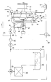
- An internal combustion engine 1 of the reciprocating piston type is used to drive a lifting screw 2 of a rotary wing aircraft, not shown, which is also referred to as a helicopter.
- the internal combustion engine 1 comprises a crankcase 3, a crankshaft 4 and an oil sump 5.
- a flow coupling 6 is provided, which is formed by a pump wheel 7 and a turbine wheel 8.
- the pump wheel 7 and the turbine wheel 8 are accommodated in a housing 9.
- the housing 9 delimits a space 10 and is connected to the crankcase 3 via flanges 11, 12.
- the pump wheel 7 (drive wheel) is connected to the crankshaft 4 by means of a flywheel 13, whereas the turbine wheel 8 (driven wheel) is connected to the lifting screw 2 having a shaft 15 with the intermediary of a transfer case 14.
- a 16 with an oil circuit is designated, with which oil is supplied via line 17 to the fluid coupling 6.
- the oil leaving the fluid coupling 6 exits at 18, where the line 19 runs, which is connected via line 20 to the lubricating oil circuit of the internal combustion engine 1, that is to say is connected to the oil sump 5.
- a check valve 21, a suction pump 22, a thermostatic valve 23, a feed pump 24, a filter 25 and a clutch valve 26 are connected in the oil circuit 16.
- a return line 27 leads to the lubricating oil circuit of the internal combustion engine 1 , which is followed by an oil tank 29.
- a line 30, which is provided with a further return line 31, leads the oil from the oil container 29 back into the flow line 17.
- the suction pump 22 is connected to an electrical generator 32 which is operatively connected to the lifting screw 2.
- Nozzles 33, 34 are provided on the pump wheel 7, which open into the space 10.
- the circulation of the oil circuit 16 in Gear set After the start-up of the internal combustion engine 1, the circulation of the oil circuit 16 in Gear set. After the operating temperature has been reached, the internal combustion engine 1 is run up to the continuous running speed, as a result of which the speed of the turbine wheel 8 is gradually adjusted to the speed of the pump wheel 7; now torque is transferred to the lifting screw 2.
- the pump wheel 7 In the event of faults in the internal combustion engine 1, for example the crankshaft 4 is fixed, the pump wheel 7 is also stationary.
- the oil, accelerated by the turbine wheel 7, rapidly enters the space 10, the flow coupling 6 empties, the oil from the suction pump 22, which is now operated with the current of the generator 32, entering the oil circuit 17; it is conveyed into the oil container 29. In this phase the valve 26 is closed.
- the lifting screw 2 is thus decoupled from the internal combustion engine 1 and the rotary-wing aircraft lands by means of autorotation.
Landscapes
- Engineering & Computer Science (AREA)
- Mechanical Engineering (AREA)
- Aviation & Aerospace Engineering (AREA)
- General Engineering & Computer Science (AREA)
- Lubrication Of Internal Combustion Engines (AREA)
- Lubrication Details And Ventilation Of Internal Combustion Engines (AREA)
- Mechanical Operated Clutches (AREA)
Applications Claiming Priority (2)
| Application Number | Priority Date | Filing Date | Title |
|---|---|---|---|
| DE3743292 | 1987-12-19 | ||
| DE19873743292 DE3743292A1 (de) | 1987-12-19 | 1987-12-19 | Kupplung |
Publications (2)
| Publication Number | Publication Date |
|---|---|
| EP0321671A2 true EP0321671A2 (fr) | 1989-06-28 |
| EP0321671A3 EP0321671A3 (fr) | 1989-11-15 |
Family
ID=6343111
Family Applications (1)
| Application Number | Title | Priority Date | Filing Date |
|---|---|---|---|
| EP88117474A Ceased EP0321671A3 (fr) | 1987-12-19 | 1988-10-20 | Embrayage |
Country Status (3)
| Country | Link |
|---|---|
| US (1) | US4970860A (fr) |
| EP (1) | EP0321671A3 (fr) |
| DE (1) | DE3743292A1 (fr) |
Families Citing this family (11)
| Publication number | Priority date | Publication date | Assignee | Title |
|---|---|---|---|---|
| DE19614589A1 (de) * | 1996-04-12 | 1997-10-16 | Voith Turbo Kg | Hydrodynamische Kupplung |
| DE19707172C1 (de) * | 1997-02-22 | 1998-10-29 | Voith Turbo Kg | Antriebseinheit für Förderanlagen, insbesondere Bandantriebsanlage |
| US6044645A (en) * | 1998-08-07 | 2000-04-04 | General Motors Corporation | Flow control for oil in transit |
| GB2407372B (en) * | 2002-04-11 | 2007-02-14 | Richard A Haase | Water combustion technology-methods,processes,systems and apparatus for the combustion of hydrogen and oxygen |
| JP3891878B2 (ja) * | 2002-05-08 | 2007-03-14 | 本田技研工業株式会社 | トルクコンバータ付き内燃機関 |
| DE102004059836A1 (de) | 2004-12-10 | 2006-06-14 | Voith Turbo Gmbh & Co. Kg | Hydrodynamische Kupplung |
| US8133027B2 (en) * | 2008-07-14 | 2012-03-13 | Hamilton Sundstrand Corporation | Integrated actuator for a propeller system |
| US8240443B2 (en) * | 2008-08-13 | 2012-08-14 | GM Global Technology Operations LLC | Powertrain with engine oil-fed torque converter |
| DE102013007544A1 (de) * | 2013-05-03 | 2014-11-06 | Voith Patent Gmbh | Hydrodynamische Maschine, insbesondere hydrodynamische Kupplung |
| US9731832B2 (en) * | 2013-06-20 | 2017-08-15 | Sikorsky Aircraft Corporation | Torque converter for rotorcraft |
| CN107922054A (zh) * | 2016-07-20 | 2018-04-17 | 美国三角鹰发动机有限公司 | 单输入发动机控制器和系统 |
Family Cites Families (15)
| Publication number | Priority date | Publication date | Assignee | Title |
|---|---|---|---|---|
| US3053051A (en) * | 1962-09-11 | Transmission | ||
| DE610491C (de) * | 1933-01-22 | 1935-03-11 | J M Voith Fa | Antriebsvorrichtung fuer Kraftfahrzeuge mittels Fluessigkeitsgetriebe nach Art der Foettingergetriebe |
| GB448560A (en) * | 1934-12-14 | 1936-06-11 | Joseph Yoxall | Improvements in or relating to power transmission mechanism for aircraft |
| US2186748A (en) * | 1935-08-20 | 1940-01-09 | Daimler Benz Ag | Hydraulic transmission for automotive purposes |
| GB478041A (en) * | 1937-03-15 | 1938-01-11 | Daimler Benz Ag | Improvements in or relating to power transmission systems embodying a hydraulic clutch |
| US2270536A (en) * | 1940-02-17 | 1942-01-20 | Gen Motors Corp | Transmission drive cooling system |
| US2416948A (en) * | 1940-10-11 | 1947-03-04 | Northrop Aircraft Inc | Hydraulic turbine type torque converter and fluid coupling |
| US2473809A (en) * | 1943-07-31 | 1949-06-21 | Bendix Aviat Corp | Fluid coupling |
| US2644535A (en) * | 1949-06-29 | 1953-07-07 | United Aircraft Corp | Fluid coupling clutch |
| GB856975A (en) * | 1957-08-07 | 1960-12-21 | Napier & Son Ltd | Gas turbine power units for helicopters |
| DE1140789B (de) * | 1961-08-03 | 1962-12-06 | Beteiligungs & Patentverw Gmbh | Stroemungsgetriebe mit aeusserem Kuehlkreislauf |
| US3955365A (en) * | 1973-12-26 | 1976-05-11 | The Garrett Corporation | Fluid coupled drive apparatus |
| GB1487752A (en) * | 1975-03-13 | 1977-10-05 | British Leyland Uk Ltd | Drive arrangements |
| JPS5649426A (en) * | 1979-09-29 | 1981-05-06 | Daihatsu Motor Co Ltd | Device for feeding and draining working oil in fluid coupling |
| SU1052765A1 (ru) * | 1982-07-23 | 1983-11-07 | Минский Дважды Ордена Ленина И Ордена Октябрьской Революции Автомобильный Завод | Система охлаждени гидромеханической передачи |
-
1987
- 1987-12-19 DE DE19873743292 patent/DE3743292A1/de not_active Withdrawn
-
1988
- 1988-10-20 EP EP88117474A patent/EP0321671A3/fr not_active Ceased
- 1988-12-19 US US07/286,077 patent/US4970860A/en not_active Expired - Fee Related
Also Published As
| Publication number | Publication date |
|---|---|
| EP0321671A3 (fr) | 1989-11-15 |
| DE3743292A1 (de) | 1989-06-29 |
| US4970860A (en) | 1990-11-20 |
Similar Documents
| Publication | Publication Date | Title |
|---|---|---|
| DE19704786C1 (de) | Einrichtung zum Ausgleich von Wechselmomenten und von Schwingungen im Antriebsstrang eines Kraftfahrzeuges mit integriertem Startergenerator | |
| EP0321671A2 (fr) | Embrayage | |
| DE2059314C3 (de) | Brennstoffzufuhranlage für ein Gasturbinentriebwerk | |
| DE2828585A1 (de) | Leistungssteuervorrichtung fuer heissgasmotoren | |
| DE3226458A1 (de) | Kraftfahrzeugmotor | |
| DE19538633A1 (de) | Pumpenaggregat | |
| EP0305761B1 (fr) | Transmission hydrostatique à réglage secondaire à circuit ouvert | |
| DE69607475T2 (de) | Schmierungsanlage für brennkraftmaschine | |
| EP0093732B1 (fr) | Dispositif pour un systeme de pression | |
| DE1929386A1 (de) | Brennkraftmaschine | |
| DE3312105C2 (fr) | ||
| DD140776A1 (de) | Vorrichtung zur uebertragung einer hin-und hergehenden bewegung | |
| DE3904399C2 (fr) | ||
| DE102018125876B4 (de) | Hubkolbenmotor | |
| DE622534C (de) | Getriebe fuer Lichtanlassmaschinen von Brennkraftmaschinen | |
| DE416883C (de) | Umlaufschmierung mit Zentrifugalabscheider zur Reinigung des Schmieroels | |
| DE742160C (de) | Von der Kurbelwelle einer Brennkraftmaschine angetriebener Windfluegel | |
| DE2437675A1 (de) | Hydraulische ein- und ausrueckbare kupplung | |
| EP3101179A1 (fr) | Appareil de travail, notamment pour un engin de chantier | |
| DE896597C (de) | Gegenlaeufige, gleichachsig angeordnete und gemeinsam zwangslaeufig im gleichen Drehzahlverhaeltnis angetriebene Verstelluftschrauben | |
| DE1810040A1 (de) | Hydrzulische Kraftuebertragungsvorrichtung | |
| DE711210C (de) | Fluessigkeitsstroemungsgetriebe mit mehreren Kreislaeufen | |
| DE429068C (de) | Hydraulische Kupplung | |
| DE3390243T1 (de) | Stammholz-Entrindungsvorrichtung mit hydraulischer Zuführung | |
| DE1145428B (de) | Rotationskolben-Brennkraftmaschine in Trochoidenbauart |
Legal Events
| Date | Code | Title | Description |
|---|---|---|---|
| PUAI | Public reference made under article 153(3) epc to a published international application that has entered the european phase |
Free format text: ORIGINAL CODE: 0009012 |
|
| AK | Designated contracting states |
Kind code of ref document: A2 Designated state(s): DE FR GB IT |
|
| PUAL | Search report despatched |
Free format text: ORIGINAL CODE: 0009013 |
|
| AK | Designated contracting states |
Kind code of ref document: A3 Designated state(s): DE FR GB IT |
|
| 17P | Request for examination filed |
Effective date: 19900315 |
|
| 17Q | First examination report despatched |
Effective date: 19910502 |
|
| STAA | Information on the status of an ep patent application or granted ep patent |
Free format text: STATUS: THE APPLICATION HAS BEEN REFUSED |
|
| 18R | Application refused |
Effective date: 19921218 |