EP0321671A2 - Clutch - Google Patents
Clutch Download PDFInfo
- Publication number
- EP0321671A2 EP0321671A2 EP88117474A EP88117474A EP0321671A2 EP 0321671 A2 EP0321671 A2 EP 0321671A2 EP 88117474 A EP88117474 A EP 88117474A EP 88117474 A EP88117474 A EP 88117474A EP 0321671 A2 EP0321671 A2 EP 0321671A2
- Authority
- EP
- European Patent Office
- Prior art keywords
- oil
- combustion engine
- internal combustion
- coupling
- pump
- Prior art date
- Legal status (The legal status is an assumption and is not a legal conclusion. Google has not performed a legal analysis and makes no representation as to the accuracy of the status listed.)
- Ceased
Links
Images
Classifications
-
- F—MECHANICAL ENGINEERING; LIGHTING; HEATING; WEAPONS; BLASTING
- F16—ENGINEERING ELEMENTS AND UNITS; GENERAL MEASURES FOR PRODUCING AND MAINTAINING EFFECTIVE FUNCTIONING OF MACHINES OR INSTALLATIONS; THERMAL INSULATION IN GENERAL
- F16D—COUPLINGS FOR TRANSMITTING ROTATION; CLUTCHES; BRAKES
- F16D33/00—Rotary fluid couplings or clutches of the hydrokinetic type
- F16D33/06—Rotary fluid couplings or clutches of the hydrokinetic type controlled by changing the amount of liquid in the working circuit
- F16D33/16—Rotary fluid couplings or clutches of the hydrokinetic type controlled by changing the amount of liquid in the working circuit by means arranged externally of the coupling or clutch
-
- B—PERFORMING OPERATIONS; TRANSPORTING
- B64—AIRCRAFT; AVIATION; COSMONAUTICS
- B64C—AEROPLANES; HELICOPTERS
- B64C27/00—Rotorcraft; Rotors peculiar thereto
- B64C27/04—Helicopters
- B64C27/12—Rotor drives
-
- B—PERFORMING OPERATIONS; TRANSPORTING
- B64—AIRCRAFT; AVIATION; COSMONAUTICS
- B64D—EQUIPMENT FOR FITTING IN OR TO AIRCRAFT; FLIGHT SUITS; PARACHUTES; ARRANGEMENTS OR MOUNTING OF POWER PLANTS OR PROPULSION TRANSMISSIONS IN AIRCRAFT
- B64D35/00—Transmitting power from power plant to propellers or rotors; Arrangements of transmissions
Definitions
- the invention relates to a clutch according to the preamble of patent claim 1.
- the object of the invention is to design the coupling that connects the internal combustion engine and the lifting screw of a rotary wing aircraft so that it is vibration-damping and wear-resistant with a good coupling function.
- This clutch should also meet the requirements for autorotation of the propeller.
- the main advantages achieved with the invention are the fact that the fluid coupling works without wear and gently transmits the forces that occur between the internal combustion engine and the propeller.
- This flow coupling which is also called dynamic fluid coupling, has a vibration-damping effect.
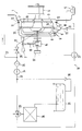
- An internal combustion engine 1 of the reciprocating piston type is used to drive a lifting screw 2 of a rotary wing aircraft, not shown, which is also referred to as a helicopter.
- the internal combustion engine 1 comprises a crankcase 3, a crankshaft 4 and an oil sump 5.
- a flow coupling 6 is provided, which is formed by a pump wheel 7 and a turbine wheel 8.
- the pump wheel 7 and the turbine wheel 8 are accommodated in a housing 9.
- the housing 9 delimits a space 10 and is connected to the crankcase 3 via flanges 11, 12.
- the pump wheel 7 (drive wheel) is connected to the crankshaft 4 by means of a flywheel 13, whereas the turbine wheel 8 (driven wheel) is connected to the lifting screw 2 having a shaft 15 with the intermediary of a transfer case 14.
- a 16 with an oil circuit is designated, with which oil is supplied via line 17 to the fluid coupling 6.
- the oil leaving the fluid coupling 6 exits at 18, where the line 19 runs, which is connected via line 20 to the lubricating oil circuit of the internal combustion engine 1, that is to say is connected to the oil sump 5.
- a check valve 21, a suction pump 22, a thermostatic valve 23, a feed pump 24, a filter 25 and a clutch valve 26 are connected in the oil circuit 16.
- a return line 27 leads to the lubricating oil circuit of the internal combustion engine 1 , which is followed by an oil tank 29.
- a line 30, which is provided with a further return line 31, leads the oil from the oil container 29 back into the flow line 17.
- the suction pump 22 is connected to an electrical generator 32 which is operatively connected to the lifting screw 2.
- Nozzles 33, 34 are provided on the pump wheel 7, which open into the space 10.
- the circulation of the oil circuit 16 in Gear set After the start-up of the internal combustion engine 1, the circulation of the oil circuit 16 in Gear set. After the operating temperature has been reached, the internal combustion engine 1 is run up to the continuous running speed, as a result of which the speed of the turbine wheel 8 is gradually adjusted to the speed of the pump wheel 7; now torque is transferred to the lifting screw 2.
- the pump wheel 7 In the event of faults in the internal combustion engine 1, for example the crankshaft 4 is fixed, the pump wheel 7 is also stationary.
- the oil, accelerated by the turbine wheel 7, rapidly enters the space 10, the flow coupling 6 empties, the oil from the suction pump 22, which is now operated with the current of the generator 32, entering the oil circuit 17; it is conveyed into the oil container 29. In this phase the valve 26 is closed.
- the lifting screw 2 is thus decoupled from the internal combustion engine 1 and the rotary-wing aircraft lands by means of autorotation.
Abstract
Description
Die Erfindung betrifft eine Kupplung nach dem Oberbegriff des Patentanspruchs 1.The invention relates to a clutch according to the preamble of patent claim 1.
Es ist bekannt (Meyer's Lexikon "Technik und exakte Naturwissenschaften 1969, Seite 622), zwischen einer Brennkraftmaschine und einer Hubschraube eines Tragschraubers der Drehflügelflugzeugbauart eine Reibungskupplung vorzusehen.It is known (Meyer's Lexikon "Technik und exact Naturwissenschaften 1969, page 622) to provide a friction clutch between an internal combustion engine and a lifting screw of a gyroplane of the rotary wing type.
Aufgabe der Erfindung ist es, die Kupplung, die die Brennkraftmaschine und die Hubschraube eines Drehflügelflugzeuges verbindet, so zu gestalten, daß sie bei guter Kupplungsfunktion schwingungsdämpfend und verschleißfest ist. Dabei sollte diese Kupplung aber auch den bei Autorotation der Luftschraube notwendigen Anforderungen gerecht werden.The object of the invention is to design the coupling that connects the internal combustion engine and the lifting screw of a rotary wing aircraft so that it is vibration-damping and wear-resistant with a good coupling function. This clutch should also meet the requirements for autorotation of the propeller.
Erfindungsgemäß wird diese Aufgabe durch die kennzeichnenden Merkmale des Patentanspruchs 1 gelöst. Weitere, die Erfindung ausgestaltende Merkmale sind in den Unteransprüchen enthalten.According to the invention, this object is achieved by the characterizing features of patent claim 1. Further features embodying the invention are contained in the subclaims.
Die mit der Erfindung hauptsächlich erzielten Vorteile sind darin zu sehen, daß die Strömungskupplung verschleißfrei arbeitet und die auftretenden Kräfte zwischen Brennkraftmaschine und Luftschraube sanft überträgt. Auch wirkt diese Strömungskupplung, die ja auch dynamische Flüssigkeitskupplung genannt wird, schwingungsdämpfend.The main advantages achieved with the invention are the fact that the fluid coupling works without wear and gently transmits the forces that occur between the internal combustion engine and the propeller. This flow coupling, which is also called dynamic fluid coupling, has a vibration-damping effect.
Darüber hinaus ist bei dem Arbeitsbereich Autorotation der Luftschraube - ihre Drehung ist ausschließlich auf aerodynamische Momente zurückzuführen - der sich z.B. nach unerwünscht festgesetzter Brennkraftmaschine ergibt, die Momentenübertragung zwischen Pumpenrad und Turbinenrad innerhalb kürzester Zeit weitestgehend unterbrochen. Anders ausgedruckt, das Öl entweicht rasch aus der Strömungskupplung und die Drehbewegung der Luftschraube ist im Sinne der Autorotation sichergestellt.In addition, in the autorotation work area of the propeller - its rotation is exclusively due to aerodynamic moments - which results, for example, from an undesirably fixed internal combustion engine, the torque transmission between the pump wheel and turbine wheel is largely interrupted within a very short time. In other words, the oil quickly escapes from the fluid coupling and the rotation of the propeller is ensured in the sense of autorotation.
In der Zeichnung, die eine einzige Figur einer Kupplung zwischen Brennkraftmaschine und Luftschraube eines Drehflügelflugzeuges wiedergibt, ist ein Ausführungsbeispiel der Erfindung gezeigt, das nachstehend näher beschrieben ist.In the drawing, which shows a single figure of a clutch between the internal combustion engine and the propeller of a rotary wing aircraft, an embodiment of the invention is shown, which is described in more detail below.
Eine Brennkraftmaschine 1 der Hubkolbenbauart dient zum Antrieb einer Hubschraube 2 eines nicht näher gezeigten Drehflügelflugzeugs, das auch als Hubschrauber bezeichnet wird. Die Brennkraftmaschine 1 umfaßt ein Kurbelgehäuse 3, eine Kurbelwelle 4 und einen Ölsumpf 5. Zwischen Brennkraftmaschine 1 und Hubschraube 2 ist eine Strömungskupplung 6 vorgesehen, die durch ein Pumpenrad 7 und ein Turbinenrad 8 gebildet wird. Das Pumpenrad 7 und das Turbinenrad 8 sind in einem Gehäuse 9 untergebracht. Das Gehäuse 9 begrenzt einen Raum 10 und ist über Flansche 11, 12 mit dem Kurbelgehäuse 3 verbunden. Das Pumpenrad 7 (Antriebsrad) ist unter Vermittlung eines Schwungrades 13 mit der Kurbelwelle 4 verbunden, wogegen das Turbinenrad 8 (Abtriebsrad) unter Zwischenschaltung eines Verteilergetriebes 14 mit der eine Welle 15 aufweisenden Hubschraube 2 verbunden ist.An internal combustion engine 1 of the reciprocating piston type is used to drive a
Mit 16 ist ein Ölkreislauf bezeichnet, mit dem über die Leitung 17 der Strömungskupplung 6 Öl zugeführt wird. Das die Strömungskupplung 6 verlassende Öl tritt bei 18 aus, wo die Leitung 19 verläuft, die über die Leitung 20 an den Schmierölkreislauf der Brennkraftmaschine 1, will heißen an den Ölsumpf 5 angeschlossen ist. In den Ölkreislauf 16 geschaltet ist ein Rückschlagventil 21, eine Absaugpumpe 22, ein Thermostatventil 23, eine Förderpumpe 24, ein Filter 25 und ein Kupplungsventil 26. Eine Rücklaufleitung 27 führt zum Schmierölkreislauf der Brennkraftmaschine 1. Das Thermostatventil 23 steuert erwärmtes Öl zu einem Ölkühler 28, dem ein Ölbehälter 29 nachgeschaltet ist. Eine Leitung 30, die mit einer weiteren Rücklaufleitung 31 versehen ist, führt das Öl aus dem Ölbehälter 29 wieder in den Vorlauf der Leitung 17.16 with an oil circuit is designated, with which oil is supplied via
Die Absaugpumpe 22 ist an einen elektrischen Generator 32 angeschlossen, der in Wirkverbindung mit der Hubschraube 2 steht.The
Am Pumpenrad 7 sind Düsen 33, 34 vorgesehen, die in den Raum 10 münden. Nach dem Anlauf der Brennkraftmaschine 1 wird der Umlauf des Ölkreislaufs 16 in Gang gesetzt. Nach Erreichen der Betriebstemperatur wird die Brennkraftmaschine 1 auf Dauerlaufdrehzahl hochgefahren, wodurch eine allmähliche Angleichung der Drehzahl des Turbinenrades 8 an die Drehzahl des Pumpenrades 7 erfolgt; jetzt wird Drehmoment auf die Hubschraube 2 übertragen.
Bei Störungen der Brennkraftmaschine 1, beispielsweise die Kurbelwelle 4 ist fest, steht auch das Pumpenrad 7. Die mit höherem Trägheitsmoment behaftete Hubschraube 2 läuft weiter; die Autorotation, hervorgerufen durch aerodynamische Momente, beginnt. Das Öl tritt, beschleunigt durch das Turbinenrad 7, rasch in den Raum 10 ein, die Strömungskupplung 6 entleert sich, wobei das Öl von der Absaugpumpe 22, die ja jetzt mit dem Strom des Generators 32 betrieben wird, in den Ölkreislauf 17 ein; es wird in den Ölbehälter 29 gefördert. In dieser Phase ist das Ventil 26 geschlossen. Damit ist die Hubschraube 2 von der Brennkraftmaschine 1 entkoppelt und das Drehflügelflugzeug landet durch Autorotation.In the event of faults in the internal combustion engine 1, for example the
Claims (7)
Applications Claiming Priority (2)
| Application Number | Priority Date | Filing Date | Title |
|---|---|---|---|
| DE19873743292 DE3743292A1 (en) | 1987-12-19 | 1987-12-19 | CLUTCH |
| DE3743292 | 1987-12-19 |
Publications (2)
| Publication Number | Publication Date |
|---|---|
| EP0321671A2 true EP0321671A2 (en) | 1989-06-28 |
| EP0321671A3 EP0321671A3 (en) | 1989-11-15 |
Family
ID=6343111
Family Applications (1)
| Application Number | Title | Priority Date | Filing Date |
|---|---|---|---|
| EP88117474A Ceased EP0321671A3 (en) | 1987-12-19 | 1988-10-20 | Clutch |
Country Status (3)
| Country | Link |
|---|---|
| US (1) | US4970860A (en) |
| EP (1) | EP0321671A3 (en) |
| DE (1) | DE3743292A1 (en) |
Families Citing this family (11)
| Publication number | Priority date | Publication date | Assignee | Title |
|---|---|---|---|---|
| DE19614589A1 (en) * | 1996-04-12 | 1997-10-16 | Voith Turbo Kg | Hydrodynamic clutch |
| DE19707172C1 (en) * | 1997-02-22 | 1998-10-29 | Voith Turbo Kg | Drive unit for conveyor systems, in particular belt drive system |
| US6044645A (en) * | 1998-08-07 | 2000-04-04 | General Motors Corporation | Flow control for oil in transit |
| KR20040105867A (en) * | 2002-04-11 | 2004-12-16 | 에이. 하세 리차드 | Water combustion technology-methods, processes, systems and apparatus for the combustion of hydrogen and oxygen |
| JP3891878B2 (en) * | 2002-05-08 | 2007-03-14 | 本田技研工業株式会社 | Internal combustion engine with torque converter |
| DE102004059836A1 (en) | 2004-12-10 | 2006-06-14 | Voith Turbo Gmbh & Co. Kg | Hydrodynamic coupling |
| US8133027B2 (en) * | 2008-07-14 | 2012-03-13 | Hamilton Sundstrand Corporation | Integrated actuator for a propeller system |
| US8240443B2 (en) * | 2008-08-13 | 2012-08-14 | GM Global Technology Operations LLC | Powertrain with engine oil-fed torque converter |
| DE102013007544A1 (en) * | 2013-05-03 | 2014-11-06 | Voith Patent Gmbh | Hydrodynamic machine, in particular hydrodynamic coupling |
| US9731832B2 (en) * | 2013-06-20 | 2017-08-15 | Sikorsky Aircraft Corporation | Torque converter for rotorcraft |
| US20180023489A1 (en) * | 2016-07-20 | 2018-01-25 | Deltahawk Engines, Inc. | Single Input Engine Controller and System |
Citations (7)
| Publication number | Priority date | Publication date | Assignee | Title |
|---|---|---|---|---|
| DE610491C (en) * | 1933-01-22 | 1935-03-11 | J M Voith Fa | Drive device for motor vehicles by means of fluid transmission on the type of foetting gear |
| GB448560A (en) * | 1934-12-14 | 1936-06-11 | Joseph Yoxall | Improvements in or relating to power transmission mechanism for aircraft |
| US2644535A (en) * | 1949-06-29 | 1953-07-07 | United Aircraft Corp | Fluid coupling clutch |
| GB856975A (en) * | 1957-08-07 | 1960-12-21 | Napier & Son Ltd | Gas turbine power units for helicopters |
| US3053051A (en) * | 1962-09-11 | Transmission | ||
| US3164961A (en) * | 1961-08-03 | 1965-01-12 | Voith Getriebe Kg | Hydrodynamic fluid flow machine |
| GB1487752A (en) * | 1975-03-13 | 1977-10-05 | British Leyland Uk Ltd | Drive arrangements |
Family Cites Families (8)
| Publication number | Priority date | Publication date | Assignee | Title |
|---|---|---|---|---|
| US2186748A (en) * | 1935-08-20 | 1940-01-09 | Daimler Benz Ag | Hydraulic transmission for automotive purposes |
| GB478041A (en) * | 1937-03-15 | 1938-01-11 | Daimler Benz Ag | Improvements in or relating to power transmission systems embodying a hydraulic clutch |
| US2270536A (en) * | 1940-02-17 | 1942-01-20 | Gen Motors Corp | Transmission drive cooling system |
| US2416948A (en) * | 1940-10-11 | 1947-03-04 | Northrop Aircraft Inc | Hydraulic turbine type torque converter and fluid coupling |
| US2473809A (en) * | 1943-07-31 | 1949-06-21 | Bendix Aviat Corp | Fluid coupling |
| US3955365A (en) * | 1973-12-26 | 1976-05-11 | The Garrett Corporation | Fluid coupled drive apparatus |
| JPS5649426A (en) * | 1979-09-29 | 1981-05-06 | Daihatsu Motor Co Ltd | Device for feeding and draining working oil in fluid coupling |
| SU1052765A1 (en) * | 1982-07-23 | 1983-11-07 | Минский Дважды Ордена Ленина И Ордена Октябрьской Революции Автомобильный Завод | Hydromechanical transmission cooling system |
-
1987
- 1987-12-19 DE DE19873743292 patent/DE3743292A1/en not_active Withdrawn
-
1988
- 1988-10-20 EP EP88117474A patent/EP0321671A3/en not_active Ceased
- 1988-12-19 US US07/286,077 patent/US4970860A/en not_active Expired - Fee Related
Patent Citations (7)
| Publication number | Priority date | Publication date | Assignee | Title |
|---|---|---|---|---|
| US3053051A (en) * | 1962-09-11 | Transmission | ||
| DE610491C (en) * | 1933-01-22 | 1935-03-11 | J M Voith Fa | Drive device for motor vehicles by means of fluid transmission on the type of foetting gear |
| GB448560A (en) * | 1934-12-14 | 1936-06-11 | Joseph Yoxall | Improvements in or relating to power transmission mechanism for aircraft |
| US2644535A (en) * | 1949-06-29 | 1953-07-07 | United Aircraft Corp | Fluid coupling clutch |
| GB856975A (en) * | 1957-08-07 | 1960-12-21 | Napier & Son Ltd | Gas turbine power units for helicopters |
| US3164961A (en) * | 1961-08-03 | 1965-01-12 | Voith Getriebe Kg | Hydrodynamic fluid flow machine |
| GB1487752A (en) * | 1975-03-13 | 1977-10-05 | British Leyland Uk Ltd | Drive arrangements |
Also Published As
| Publication number | Publication date |
|---|---|
| EP0321671A3 (en) | 1989-11-15 |
| US4970860A (en) | 1990-11-20 |
| DE3743292A1 (en) | 1989-06-29 |
Similar Documents
| Publication | Publication Date | Title |
|---|---|---|
| DE19704786C1 (en) | Device for compensating for alternating torques and vibrations in the drive train of a motor vehicle with an integrated starter generator | |
| DE2809847C2 (en) | Thermostat controlled clutch | |
| EP1521899B1 (en) | Electrically driven camshaft adjuster | |
| EP0321671A2 (en) | Clutch | |
| EP0033372B1 (en) | Braking gear for valve controlled internal combustion engines | |
| DE19538633A1 (en) | Pump unit | |
| EP0305761B1 (en) | Secondarily controlled hydrostatic transmission with an open circuit | |
| EP0080670B1 (en) | Rotation device for suspended loads | |
| DE836718C (en) | Flow coupling, especially for motor vehicle drives with internal combustion engines and for electrical transmission with squirrel cage motors | |
| DE69913452T2 (en) | Graduated seal and bushing | |
| DE1929386A1 (en) | Internal combustion engine | |
| WO1997029272A1 (en) | Adjusting cylinder of a camshaft adjuster on which a separate oil supply device can act | |
| DE19748907C1 (en) | Drive head for a rotationally drivable linkage, especially for driving a borehole pump | |
| DE19841853A1 (en) | Individual blade control device for a helicopter main rotor makes use of the swash plate to transfer control movements | |
| DD140776A1 (en) | DEVICE FOR TRANSMITTING A HORIZONTAL MOVEMENT | |
| DE622534C (en) | Gear for light starting machines of internal combustion engines | |
| DE742160C (en) | Wind wing driven by the crankshaft of an internal combustion engine | |
| DE2305539A1 (en) | VALVE CONTROLLED HYDRAULIC CLUTCH | |
| DE390775C (en) | Device for avoiding the transmission of vibrations in power plants, in particular ship propulsion systems | |
| DE2437675A1 (en) | HYDRAULIC CLUTCH AND RELEASE | |
| DE102020121596B3 (en) | Pump module | |
| EP0041110A2 (en) | Adjustment of injection timing using a centrifugal governor | |
| DE429068C (en) | Hydraulic clutch | |
| DE4405554C1 (en) | Supplementary device for a combustion engine | |
| US2061670A (en) | Hydraulic mechanism |
Legal Events
| Date | Code | Title | Description |
|---|---|---|---|
| PUAI | Public reference made under article 153(3) epc to a published international application that has entered the european phase |
Free format text: ORIGINAL CODE: 0009012 |
|
| AK | Designated contracting states |
Kind code of ref document: A2 Designated state(s): DE FR GB IT |
|
| PUAL | Search report despatched |
Free format text: ORIGINAL CODE: 0009013 |
|
| AK | Designated contracting states |
Kind code of ref document: A3 Designated state(s): DE FR GB IT |
|
| 17P | Request for examination filed |
Effective date: 19900315 |
|
| 17Q | First examination report despatched |
Effective date: 19910502 |
|
| STAA | Information on the status of an ep patent application or granted ep patent |
Free format text: STATUS: THE APPLICATION HAS BEEN REFUSED |
|
| 18R | Application refused |
Effective date: 19921218 |