EP0320189B1 - Kabelverschlussvorrichtung - Google Patents
Kabelverschlussvorrichtung Download PDFInfo
- Publication number
- EP0320189B1 EP0320189B1 EP88311499A EP88311499A EP0320189B1 EP 0320189 B1 EP0320189 B1 EP 0320189B1 EP 88311499 A EP88311499 A EP 88311499A EP 88311499 A EP88311499 A EP 88311499A EP 0320189 B1 EP0320189 B1 EP 0320189B1
- Authority
- EP
- European Patent Office
- Prior art keywords
- casing
- splice
- closure
- line
- section
- Prior art date
- Legal status (The legal status is an assumption and is not a legal conclusion. Google has not performed a legal analysis and makes no representation as to the accuracy of the status listed.)
- Expired - Lifetime
Links
- 238000010276 construction Methods 0.000 claims abstract description 18
- XLYOFNOQVPJJNP-UHFFFAOYSA-N water Substances O XLYOFNOQVPJJNP-UHFFFAOYSA-N 0.000 claims abstract description 12
- 230000007613 environmental effect Effects 0.000 claims abstract description 7
- 230000013011 mating Effects 0.000 claims 2
- 238000000926 separation method Methods 0.000 claims 1
- 238000005728 strengthening Methods 0.000 claims 1
- 210000002105 tongue Anatomy 0.000 description 8
- 238000000034 method Methods 0.000 description 6
- 210000005069 ears Anatomy 0.000 description 5
- 238000007789 sealing Methods 0.000 description 5
- 238000009413 insulation Methods 0.000 description 4
- 239000000463 material Substances 0.000 description 4
- 230000015572 biosynthetic process Effects 0.000 description 3
- 238000000071 blow moulding Methods 0.000 description 3
- 230000006835 compression Effects 0.000 description 3
- 238000007906 compression Methods 0.000 description 3
- 238000004519 manufacturing process Methods 0.000 description 3
- 239000004033 plastic Substances 0.000 description 3
- 229920003023 plastic Polymers 0.000 description 3
- 239000004698 Polyethylene Substances 0.000 description 2
- 238000004873 anchoring Methods 0.000 description 2
- 239000004035 construction material Substances 0.000 description 2
- 239000012774 insulation material Substances 0.000 description 2
- 238000012423 maintenance Methods 0.000 description 2
- 238000000465 moulding Methods 0.000 description 2
- -1 polyethylene Polymers 0.000 description 2
- 229920000573 polyethylene Polymers 0.000 description 2
- 241001465754 Metazoa Species 0.000 description 1
- 230000002411 adverse Effects 0.000 description 1
- 230000005540 biological transmission Effects 0.000 description 1
- 230000005494 condensation Effects 0.000 description 1
- 238000009833 condensation Methods 0.000 description 1
- 239000004020 conductor Substances 0.000 description 1
- 229920001971 elastomer Polymers 0.000 description 1
- 238000009434 installation Methods 0.000 description 1
- 230000003993 interaction Effects 0.000 description 1
- 230000001681 protective effect Effects 0.000 description 1
- 238000010079 rubber tapping Methods 0.000 description 1
- 229920002725 thermoplastic elastomer Polymers 0.000 description 1
- 230000007704 transition Effects 0.000 description 1
Images


Classifications
-
- H—ELECTRICITY
- H02—GENERATION; CONVERSION OR DISTRIBUTION OF ELECTRIC POWER
- H02G—INSTALLATION OF ELECTRIC CABLES OR LINES, OR OF COMBINED OPTICAL AND ELECTRIC CABLES OR LINES
- H02G15/00—Cable fittings
- H02G15/08—Cable junctions
- H02G15/10—Cable junctions protected by boxes, e.g. by distribution, connection or junction boxes
- H02G15/113—Boxes split longitudinally in main cable direction
-
- H—ELECTRICITY
- H02—GENERATION; CONVERSION OR DISTRIBUTION OF ELECTRIC POWER
- H02G—INSTALLATION OF ELECTRIC CABLES OR LINES, OR OF COMBINED OPTICAL AND ELECTRIC CABLES OR LINES
- H02G15/00—Cable fittings
- H02G15/08—Cable junctions
- H02G15/10—Cable junctions protected by boxes, e.g. by distribution, connection or junction boxes
- H02G15/117—Cable junctions protected by boxes, e.g. by distribution, connection or junction boxes for multiconductor cables
-
- H—ELECTRICITY
- H02—GENERATION; CONVERSION OR DISTRIBUTION OF ELECTRIC POWER
- H02G—INSTALLATION OF ELECTRIC CABLES OR LINES, OR OF COMBINED OPTICAL AND ELECTRIC CABLES OR LINES
- H02G15/00—Cable fittings
- H02G15/08—Cable junctions
- H02G15/18—Cable junctions protected by sleeves, e.g. for communication cable
- H02G15/192—Cable junctions protected by sleeves, e.g. for communication cable with support means for ends of the sleeves
Definitions
- the present invention relates to the cable splice closures, in particular to a double-wall cable splice closure.
- the invention particularly concerns cable splice closures such as may be used in the electrical transmission and telecommunications industries as aerial closures.
- Cables such as telecommunication cables, may carry hundreds and sometimes thousands of pairs of insulated wires, enclosed within flexible shields or tubular sheaths.
- a splice or splice area is created.
- the splice area should be enclosed for protection from the environment. For example, if the closure is an aerial closure, used with aerially suspended cables, protection against damaging interference from weather elements, animals, plants and so forth is necessary.
- splice closures Structures or arrangements for enclosing such portions of cables are frequently referred to as "splice closures". Such closures are typically adapted to enclose therein at least two, and sometimes more, “cable ends.”
- Splice closures generally comprise an elongate, typically cylindrical, outer casing having first and second opposite ends. Cables to be joined at the splice area(s) are generally directed into the casing through the casing ends. At each of the casing ends, seal means are provided in order to ensure an environmental seal around the cables, i.e., between the cables and the interior of the cable closure.
- An aerial closure is adapted to be used when suspended in the air, typically from a support cable or the like. Through the use of such a closure, a cable splice for suspended cables is accommodated. Typically, means are provided to ensure a conductive, and therefore grounding, contact between the cable sheaths of cables spliced in the closure.
- An example of an aerial closure is shown in U.S.A. patent No. 3,701,835 which discloses a terminal unit to permit drop wires to be spliced to the cable and it comprises a body portion and an access cover, hinged to the body portion and held closed by a spring catch.
- End plugs are lodged between the inner surface of the inner cover and some transverse ribs to deter the entry of foreign matter into the cable compartment.
- the closure incorporates an inner access cover to restrict access to the cable splice.
- U.S.A. patent No. 3,088,495 discloses a double walled strip which can be used, when bent transversely into a tube, to wrap about smaller tubes, cables or the like. It is formed of a plastic material and extruded flat. This patent does not disclose the formation of cavities within the structure or the use of end walls to form closed cavities. The patent teaches that the inner wall may be slit-lengthwise to create separate wraps for bundles of wires or cover the closure within the tube, sloping ribs and grooves are provided along the strip length to hold the strip in the bent form, but no hinged section is illustrated. The novel features and advantages of the present invention are not present in this disclosure.
- a sealing arrangement with cable extending into the cable closure must be provided. In some arrangements this may be provided by means of structural members permanently mounted on the enclosure. In others, separable end caps or washers may be utilized in association with the closure. When this latter type of arrangement is used, it is necessary and desirable for the closure to include means facilitating mounting and positioning of the end caps or washers therein.
- the closure should be readily mountable around an aerial cable splice, or the like. This is facilitated by appropriate hanger means for association with the support cable, and also appropriate means for permitting the enclosure to be selectively opened or closed, around an associated cable splice and end cap arrangements that fit over existing cables.
- a multi-piece system is avoided.
- Conventional multi-piece systems can be difficult to assemble, especially by workers supported by a ladder, bucket system or the like. The problems are exacerbated if the worker is operating under adverse conditions, such as in high winds or otherwise inclement weather.
- a cable splice closure be readily manipulatable to provide access to the interior thereof, and any enclosed cable splice arrangement.
- the arrangement is such as to generally inhibit unintended or inadvertent opening.
- a quick opening system is provided, for convenience.
- the arrangement is such that opening can be accomplished without removal of the arrangement from an associated support cable.
- the closure may be necessary for a worker to manipulate elements inside.
- the arrangement is organized such that when opened, many portions of the cable splice(s) are in view, and are readily accessible for maintenance.
- Cable splices may be of a variety of types, and include fairly simple two-cable arrangements as well as very complex multi-cable arrangements. Some arrangements may be very large in transverse or longitudinal extension, whereas others may be very small. It would be preferred that a cable enclosure arrangement be selectively adjustable or extendable in length, to accommodate cable splices requiring greater volume.
- a cable enclosure should provide a good protective shield to the environment.
- cable closures include means insulating the cable splice from sudden changes in temperature. Preferably this is accomplished at a relatively low cost, and without a substantial increase in complexity of manufacture.
- closure system be readily manufactured in a relatively inexpensive manner, and by mass manufacturing techniques.
- the present invention concerns a cable closure for use in providing environmental protection to a cable splice or the like.
- Cable closures according to the present invention are particularly well-adapted for use as aerial closures, i.e., in use suspended from a support cable or the like.
- the preferred cable closures comprise a generally cylindrical casing formed as a single unit or piece, with a longitudinal hinge extending completely along a sidewall thereof.
- the hinge permits the closure to be opened along an opposite opening seam as necessary, for example during installation about a cable splice and/or for access to an enclosure cable splice.
- the hinge is a compression molded hinge.
- compression molded hinge is meant to refer to a hinge which is formed as an integral part of the closure casing, for example during molding.
- the preferred enclosure also includes means facilitating mounting to an aerial support cable.
- the means is such that when mounted, and opened along the hinge line, the closure is oriented to provide a good viewing of, and convenient access to, an enclosed cable splice.
- This is accomplished in the preferred embodiment by providing for orientation of mounting members, on the casing, rotationally about 125-145 degrees, and preferably about 135 degrees, around the said casing, from the hinge, when the hinge is positioned substantially in the center of said circular casing, i.e. approximately 180 degrees, rotationally, from the openable or opening seam. In general, this results from providing the casing with first and second halves or members, separated along the hinge; and, by mounting the casing to the support cable by means positioned about 125-145 degrees around the casing first half, from the hinge.
- Enclosures according to the present invention have a double-wall construction.
- the provision of a double-wall throughout substantial sidewall portions of the closure facilitates insulation against sudden changes in temperature.
- the double-wall construction facilitates overall casing rigidity and integrity, with a light-weight construction.
- the double-wall construction provides a second layer of protection against exterior damage, for example against wind, ice or hail damage.
- the double-wall structure facilitates provision of features such as a water drain or trough means in an interior of the casing, to preferentially direct any water, which may leak therein, outwardly from the casing and away from an enclosed cable splice.
- Preferred closures according to the present invention are adapted to be utilized in association with end cap arrangements, positionable generally at opposite ends thereof to provide a sealing arrangement with associated cable members directed to the splice. End cap arrangements affording changes in relative alignment of cables directed into the closure are preferred. A variety of end cap arrangements may be utilized in association with closures including the above features. Preferred, is a cooperating tab and recess arrangement. In a particular preferred embodiment, a mounting tab means is provided in a selected portion of the enclosure, so that even when the closure is opened, the end cap arrangement is maintained secured in a selected position.
- Preferred closures according to the present invention are readily extendable, generally by means of associating therewith an extension.
- Preferred enclosures include a center line, cut-line, or portion across which the closure can be readily cut or separated, for example into two opposite, generally cylindrical halves. In this manner, any selected closure according to preferred embodiments can be cut in half to provide end extensions for another, uncut or intact, closure. Intact closures can be increased in length by one-half units.
- the casing is provided with a central portion, and first and second opposite end portions.
- the cut-line is centrally positioned in the central portion; dividing same into first and second sections.
- the casing is thus readily separable into two members, each comprising a section, preferably about half, of the original casing central portion and each having an end portion thereon; the separated sections being substantially mirror images of one another.
- Each central portion section includes an end portion-receiving area therein, substantially adjacent the cut-line. After a closure has been separated along the cut line, each resulting section can be used to engage and extend an intact closure, by receipt of an end portion on the intact closure into the end portion-receiving area of the separated section. Generally, extension is accomplished by opening of the closure half-section, or extension, along its opening seam, and then enclosing same about a closed end portion of the intact closure.
- interlocking means are provided to facilitate a secure, environmentally resistant, engagement with respect to both longitudinal and rotational stresses between engaged pieces.
- a cooperating tongue and groove arrangement is provided.
- Preferred enclosures according to the present invention may be blow molded from plastics, such as polyethylene materials. It is an advantage of the present invention that the structure described can be blow molded, with a double-wall construction, using normal parison techniques.
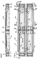
- Fig. 1 is a fragmentary, perspective, environmental view of a closure according to the present invention shown in use: enclosing a cable splice arrangement involving four cables; and, suspended from a support cable.
- Figure 2 is an enlarged, fragmentary, front elevational view of the environment shown in Fig. 1, but with the closure indicated in an open orientation, for viewing and access to otherwise enclosed cable splice areas.
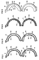
- Fig.3 is an end elevational view of the arrangement shown in Fig. 2, taken from the orientation of line 3-3, Fig. 2.
- Fig. 4 is a front elevational view of a closure according to the present invention; Fig. 4 generally illustrating the closure opened along a hinge thereof, with the view being of an interior of the closure.
- Fig. 5 is a side elevational view taken generally from the perspective of line 5-5, Fig. 4.
- Fig. 6 is an enlarged, fragmentary, cross-sectional view generally taken along line 6-6, Fig. 4.
- Fig. 7 is an enlarged, fragmentary, cross-sectional view taken generally along line 7-7, Fig. 4.
- Fig. 8 is an enlarged, fragmentary, end elevational view taken generally from the point of view of line 8-8, Fig. 4.
- Fig. 9 is an enlarged, fragmentary, cross-sectional view taken generally along line 9-9, Fig. 4.
- Fig. 10 is an enlarged, fragmentary, cross-sectional view taken generally along line 10-10, Fig. 4.
- Fig. 11 is an enlarged, fragmentary, cross-sectional view taken generally along line 11-11, Fig. 4.
- Fig. 12 is an enlarged, side elevational view of a closure according to the present invention shown extended by one-half section taken from a second closure according to the present invention.
- Fig. 13 is an enlarged, schematic, end elevational view of a closure according to the present invention; the drawing illustrating a preferred latch system.
- Fig. 14 is an enlarged, schematic, end elevational view of a closure according to the present invention; the drawing illustrating operation of the preferred latch arrangement of Fig. 13.
- the reference numeral 1 generally designates a splice closure according to the present invention, represented in a typical environment of use. More specifically, splice closure 1 is shown suspended from a support cable 3, by hanger means including hangers 4. Four cables, 5, 6, 7 and 8 are shown extending into an interior of splice closure 1, toward a cable splice arrangement enclosed therein.
- splice closure 1 comprises a casing 10 openable along an edge or opening seam 11.
- casing 10 comprises first and second sections 15 and 16, hingedly connected to one another along a hinge line 18, Fig. 2.
- hinge line 18 is defined by a compression molded hinge 19. That is, hinge 19 is integral with casing sections 15 and 16.
- casing 10 is molded from a durable plastic, such as a polyethylene or the like. In this manner, hinge 19 can be readily formed integrally with the casing sections 15 and 16, when molded.
- Preferred casings 10 according to the present invention are blow molded, and in fact it is an advantage of the present invention that the casing design chosen is susceptible to manufacture by blow molding techniques, in a relatively inexpensive and rapid manner.
- each section 15 and 16 is about a one-half side of the casing 10. That is, each of sections 15 and 16 is substantially semi-cylindrical in configuration.
- casing 10 has an elongate, substantially cylindrical, shape with first and second opposite end portions 21 and 22, mounted on, secured to or integral with, a central portion 23.
- the casing 10 has an integral structure.
- the cylindrical casing 10 is selectively maintained secured in a closed conformation, Fig. 1, by latch means or arrangements 25.
- Latch arrangements 25 may be any of a variety of conventional arrangements whereby section 16 can be selectively maintained secured to section 15, along seam 11.
- each latch arrangement 25 includes an actuator handle 28 and a securing latch 29, see Fig. 13 and 14.
- the securing latch 29 is organized such that a protrusion 31 on section 15 can be readily engaged thereby.
- Actuator handle 28 in a conventional manner, can be operated to apply leverage to the securing latch 29, drawing the protrusion 31 toward the section 16, or vice versa . In this manner the casing 10 can be readily closed, and opened, as desired. Further, latch arrangement 25 can be readily operated, when necessary, to provide access to an interior of the casing or canister 10. Further detail concerning latch arrangements 25 is presented below, with respect to a discussion of Figs. 13 and 14.
- casing 10 is shown opened along seam 11; i.e. section 16 is swung open and downward around hinge 19, with respect to section 15. As a result, the inside of casing 10 is viewable. Cables 5 and 7 are represented as spliced to one another at splice area 35, and cables 6 and 8 are shown spliced to one another at splice area 36. It is, of course, a major functional purpose for casing 10 to provide protection for the splice areas 35 and 36. It is to be understood that the splice areas 35 and 36 depicted are representative only, and a variety of types, or arrangements, may be involved.
- each of the cable members 5, 6, 7 and 8 is from the exterior environment to an interior 37 of the casing 10.
- sealing engagement is necessary and desirable between each of the cables 5, 6, 7 and 8 and the casing 10, to provide for an environmental seal.
- a variety of means may be utilized as the seal means, or end seal means, for the casing 10.
- the end seal comprises first and second opposite end cap arrangements 40 and 41, positioned in opposite end portions 21 and 22 respectively, of the casing 10.
- the particular end cap arrangements 40 and 41 depicted each comprise a circular sealing member having a pair of apertures therethrough to accommodate two cables, for example cables 5 and 6 for arrangement 40, in a sealing manner.
- Each end cap arrangement 40 and 41 includes, in association therewith, a pair of opposite mounting ears, for example ears 44 and 45 for arrangement 40, Fig. 2.
- the mounting ears are preferably flexible extensions of rubber, or thermoplastic rubber material, which can be snap-fit or friction-fit into a securing or retaining means comprising tab arrangements formed in casing section 15.
- Mounting tabs, for receipt of mounting ears 44 and 45, are discussed in further detail below with respect to other features of the casing 10. It is noted that since the casing 10 is adapted to include mounting tabs in section 15, i.e. an upper half of the casing, when the casing 10 is opened, Fig. 2, the end cap arrangements 40 and 41 remain attached to, and suspended from, casing section 15, thus maintaining the splice areas 35 and 36 fixed in position. This is advantageous, as it facilitates repair and replacement operations.
- Splice closure arrangements include numerous advantageous features. Some of these relate to and concern the following: provision of means facilitating access to enclosed splice areas, such as areas 35 and 36, for maintenance and repair; provision of means facilitating insulation from the environment; means affording rigid structure; provision of means facilitating drainage of rain water or the like which may collect within the interior 37; and, provision of means facilitating extension of the casing 10, as may be necessary to cover larger splice areas.
- provision of means facilitating access to enclosed splice areas such as areas 35 and 36, for maintenance and repair
- provision of means facilitating insulation from the environment means affording rigid structure
- provision of means facilitating drainage of rain water or the like which may collect within the interior 37
- provision of means facilitating extension of the casing 10 as may be necessary to cover larger splice areas.
- these features are provided by the following structures and elements.
- the hinge line 18 is rotationally positioned between about 125 degrees to 145 degrees, and preferably about 135 degrees, from attachment points of areas 50, whereat the hanger members 4 are secured to casing 10, mounting same on the cable 3.
- a slight overhang area of cover 51 in section 15 is provided.
- area 51 does not substantially block view of, or access to, splice areas 35 and 36. This is readily understood by examination of Fig. 3, wherein it is illustrated that the splice areas could be readily viewed from the direction of arrow 52.
- FIG. 4 the casing 10 itself is depicted.
- the drawing (Fig. 4) illustrates the casing 10 opened along the hinge line 18. The viewer's perspective is looking toward an inside 37 of the casing 10, i.e. the inside of each casing section 15 and 16.
- Fig. 5 the arrangement of Fig. 4 is depicted from a side elevation, as defined.
- Figs. 6-11 show various end elevational and cross-sectional views, defined by lines in Fig. 4.
- the casing 10 shown in Fig. 4 is substantially the same as that shown in Figs. 1-3, except Fig. 4 is not an environmental view.
- many sidewall portions of the casing 10 have a double-wall structure. That is, they have an inner wall 54 and an outer wall 55, with cavity or insulating space(s) 56 therebetween. Spaces 56 act against sudden changes in ambient temperature, to insulate the interior 37 of the closure and protect against the weather causing sudden changes in temperature of the splices.
- the double wall increases the time for temperature inside and outside to reach equilibrium. The double wall also inhibits formation of condensation on the splices, due to the insulating capabilities.
- insulating spaces 56 are air-filled insulating spaces only, and are not filled with other insulation materials.
- parts, not shown, can be provided in the outer wall 55, whereby insulating spaces 56 could be filled with some other form of insulation material. It is noted that the double wall also provides for significant impact protection.
- the double-wall construction generates advantages beyond simply insulation capabilities.
- protection against damage to splice areas, such as areas 35 and 36, due to an unexpected failure of the casing 10 is provided.
- the inner wall 54 will substantially protect the splice areas 35 and 36, until repair or replacement.
- the double-wall construction provides a strong, rigid, yet lightweight, arrangement. Further, it can be readily constructed utilizing conventional molding techniques, especially conventional blow molding techniques.
- Another advantageous feature introduced into the splice closure 1 concerns drainage means providing for drainage of interior water, for example as might leak into the splice closure 1 during a rainstorm or the like, away from splice areas 35 and 36, and outwardly from interior 37 of the casing 10.
- the drainage means of the preferred embodiment is constructed in a manner which takes advantage of the double-wall construction.
- (bottom) section 16 of the casing 10 includes first and second opposite drainage port areas 60 and 61 includes a plurality of slits 63 which communicate between an interior 37 of the casing 10, and exterior of the entire splice closure 1. It will be understood that water can leak outwardly through slits 63, from an interior 37 of the casing 10.
- drainage areas 60 and 61 are positioned such that when the casing 10 is closed, Fig. 1, the drainage areas are centered around a bottom-most portion 65 of the suspended closure 1.
- Fig. 6 One of the drainage areas 61 is viewable in cross-section in Fig. 6. Upon examination of Fig. 6 it will be apparent that the slits 63 extend through a portion 66 of the casing 10 which is not double-walled. Thus, leakage into cavity 56 between the walls 54 and 55 is unlikely.
- the drainage means includes flow-directing means to direct water flow in the interior 37 toward the opposite drainage port areas 6o and 61.
- the flow directing means comprises troughs 70 and 71 directed towards drainage areas 60 and 61 respectively.
- Each of troughs 70 and 71 becomes deeper at its associated drainage port area (60 and 61 respectively), and thus each trough acts as a funnel or channel directing water toward the drainage port areas 60 and 61.
- the troughs 70 and 71 are formed in the inner wall 54.
- the double-wall construction facilitates formation of drainage means, including troughs 70 and 71, with a relatively small amount of construction material used, and without generation of undesired surface features in the outer wall 55.
- end cap arrangements 40 and 41 are secured within top-half 15 of casing 10, and prevented from rotational movement relative thereto, by mounting ears 44 and 45 as previously discussed.
- FIG. 8 an end elevational view of the casing 10 is illustrated.
- Fig. 8 is generally taken from the perspective of line 8-8, Fig. 4, and comprises an end view of end portion 22.
- Mounting tabs 75 for engaging a mounting ear on an associated end cap arrangement 41 are shown.
- Mounting tabs 75 generally define a receiving recess or slot 76, into which a flexible mounting ear or the like can be snapped. It will be understood that tabs 75, when engaged by a mounting ear on an associated end cap arrangement 41, Fig. 2, generally prevent rotational movement of the end cap arrangement 41 relative to casing 10. Further, tabs 75 prevent end cap arrangement 41 from falling out of casing 10, when opened as illustrated in Fig. 2. Also, lip 80 partially encloses end cap arrangement 41, protecting same.
- the end cap arrangements 40 and 41 are received within recesses 81 and 82, Fig. 4. As a result of this construction, the end cap arrangements 40 and 41 are inhibited from longitudinal movement, and a good secure seal is provided.
- recesses 81 and 82 are provided in end portions 21 and 22 respectively of the casing 10.
- end portions 21 and 22 are of a substantially smaller outside diameter than central portions 90 of the casing.
- end portions 21 and 22 are sized smaller than the interior diameter of receiving areas oriented in sections 91 and 92 respectively. This results in advantages relating to extendibility of casing 10, as described below and illustrated by Fig. 12.
- casing 10 includes a first section (half) 93 and second section (half) 94, which engage one another along a center line 95.
- central line 95 is a break line, or cut-line, along which casing 10 can be readily cut in half, i.e., separated. Most preferably in the area of center line 95 a compressed, double-wall, arrangement is provided, for strength.
- section 93 could be used in Fig. 1, by attachment to end portion 21, to extend the arrangement shown.
- section 94 could be used with the arrangement shown in Fig. 1, to extend end portion 22, Fig. 12.
- each portion 97 and 98 is an end portion-receiving area appropriately sized for receipt therein of an end portion of another closure.
- each section would bring, therewith, a trough and drainage area, to the overall extended construction, Fig. 12.
- more than one extension could be provided in association with an intact casing.
- half-sections could be attached to one another.
- interlocking means are provided to ensure secure arrangement of an extension, for example, sections 93 and 94, with an associated end section, for example, end portions 21 and 22.
- this is provided by a tongue and groove interlocking arrangement.
- each end section includes a pair of parallel grooves therein.
- end portion 21 includes grooves 110 and 111
- end portion 22 includes grooves 115 and 116.
- Sections 97 and 98, Fig. 4 include tongues or ridges thereon, sized and spaced to engage or cooperate with grooves 110 and 111, or 115 and 116 as necessary.
- section 98 includes tongues 120, spaced and sized to be received within grooves 115 and 116; and, section 97 includes tongues 121, sized and spaced to be received within grooves 110 and 111. It will be readily understood that such an arrangement facilitates extension, by an intact casing, in increments using separated sections from a similar casing.
- each groove has at least one, and preferably at least two, tongues, blocks or posts 125 therein.
- each of sections 97 and 98 includes an associated recess between tongues, for example recesses 130, Fig. 9.
- the recesses 130, Fig. 9, are rotationally oriented to interlock with blocks 125, during extension of the casing 10.
- the inner wall includes two oppositely positioned recesses 130, to engage two blocks 125.
- the tongue/groove arrangement is facilitated by the double-wall structure.
- the casing outer wall 55 includes a rib/groove arrangement 135 thereon.
- This arrangement 135 is generally aligned with hangers 4, or hanger mounting areas 50, Figs. 3 and 1. That is, the rib/groove arrangement 135 is centered around a topmost portion 136 of the casing 10.
- the rib/groove arrangement 135 provides for an alternative method of mounting casing 10. Specifically, hanger members 4 could be eliminated, and a band system, not shown, could be used to attach the casing 10 to cable 3, Fig. 3. Specifically, the cable 3 could be nested in the groove of the rib/groove arrangement, to orient a casing 10 properly.
- the rib/groove arrangement 135 would also ensure proper positioning of each casing section 93 and 94 of an extended closure, relative to the support cable 3.
- an elongate hanger bar 140 may extend between hanger members 4, along the interior 37 of casing 10.
- a hanger bar may be used to ensure electrical conduction between portions of hanger members 4 within casing 10.
- hanger bars may strengthen the system and provide a site for securing the cables and splice area.
- cables 5, 6, 7 and 8 could be tied or banded to the hanger bar, for secure anchoring.
- clearance portions 141 facilitate extension of a mounting band about an associated hanger bar, not shown.
- section 141 is viewable in cross-section, in Fig. 11.
- the latch arrangements 25 will be understood by reference to Figs. 13 and 14. Operation of the handle 28 and latch 29, to secure the arrangement closed by drawing section 16 toward extension 31 is readily understood. Specifically, notch area 145 provides both for mounting of arrangement 25, and for a point of leverage. Operation is facilitated by the shapes chosen for handle 28 and latch 29.
Landscapes
- Cable Accessories (AREA)
- Laying Of Electric Cables Or Lines Outside (AREA)
- Processing Of Terminals (AREA)
- Lock And Its Accessories (AREA)
- Light Guides In General And Applications Therefor (AREA)
- Insulating Bodies (AREA)
- Mechanical Treatment Of Semiconductor (AREA)
- Led Devices (AREA)
- Formation Of Insulating Films (AREA)
- Addition Polymer Or Copolymer, Post-Treatments, Or Chemical Modifications (AREA)
- Insulated Conductors (AREA)
Claims (9)
- Spleißverschluß (1) zum Schutz gegen Umwelteinflüße für einen Luftspleiß; wobei der Spleißverschluß eine längliche, hohle Ummantelung (10) umfaßt, welche aus zwei zusammenpassenden Teilstücken (15, 16) gebildet ist, welche zur Verbindung der Teilstücke eine längs ausgerichtete Scharniereinrichtung (19) umfassen und eine enstprechende, allgemein entgegengesetzt positionierte Öffnungsnaht (11); eine Verriegelungseinrichtung (25), die so gestaltet und angeordnet ist, daß sie die Ummantelung entlang der Öffnungsnaht in geschlossener Ausrichtung hält;
dadurch gekennzeichnet, dass
jedes Ummantelungsteilstück (15, 16) einen Seitenwandabschnitt der Doppelwandkonstruktion aufweist, welche ein inneres Wandteilstuck (54) und ein äußeres Wandteilstück (55) definiert, und zwar mit mindestens einem Hohlraum dazwischen und wobei sich erste und zweite entgegengesetzte Stirnwände zwischen dem inneren Wandteilstück (54) und dem äußeren Wandteilstück (55) erstrecken, um den Hohlraum zu schließen;
wobei die Doppelwandkonstruktion mit mindestens einem dazwischenliegenden Hohlraum eine Gesamtstarrheit und Integrität der Ummantelung möglich macht, und zwar mit einer leichtgewichtigen Konstruktion. - Spleißverschluß nach Anspruch 1, dadurch gekennzeichnet, daß die Ummantelung (10) allgemein zylinderförmig ist und ein zentrales Teilstück (23) und erste und zweite entgegengesetzte Endteilstücke (21, 22) aufweist; wobei das zentrale Teilstück (23) erste und zweite zentrale Endabschnitte (97, 98) aufweist, welche durch ein zentrales, umfängliches Schnittlinienteilstück (95) getrennt sind; wobei die Ummantelung (10) entlang des Schnittlinienteilstücks leicht trennbar ist, um zwei trennbare Ummantelungsteilstücke (93, 94) zu bilden; wobei das erste Ummantelungsteilstück (93) den ersten zentralen Endabschnitt (97) umfaßt und wobei das zweite Ummantelungsteilstück (94) den zweiten zentralen Endabschnitt (98) umfaßt; und wobei die zentralen Endabschnitte (97, 98) der zylinderförmigen Ummantelung darin einen Endteilstücksaufnahmebereich aufweisen, der sich im wesentlichen nahe dem Schnittlinienteilstuck befindet und der so bemessen ist, daß er ein erstes bzw. zweites entgegengesetztes Endteilstück (21, 22) einer unversehrten Ummantelung darin aufnimmt, nachdem die zylinderförmige Ummantelung entlang dem Schnittlinienteilstück getrennt worden ist; wodurch ein unversehrter erster Spleißverschluß wahlweise durch ein Ummantelungsteilstück (93, 94) erweitert werden kann, welches durch Trennung einer zweiten Spleißummantelung (10) entlang deren Schnittlinie (95) und Anbringung an dem unversehrten ersten oder zweiten Endteilstück (21, 22) erzeugt wird.
- Spleißverschluß nach Anspruch 2, dadurch gekennzeichnet, daß die Ummantelung (10) eine Verriegelungseinrichtung (110, 111, 115, 116, 120, 121) umfaßt, welche zur Herstellung einer verriegelnden Verbindung zwischen einem Ummantelungsendteilstück-Aufnahmebereich eines zentralen Ummantelungsendabschnitts (97), (98) eines Ummantelungsteilstücks (93, 94), welches durch die Trennung einer Ummantelung entlang der Schnittlinie (95) erzeugt worden ist und einem Ummantelungsendteilstück (21, 22) eines darin wahlweise aufgenommenen unversehrten Verschlußes, gestaltet und angeordnet ist.
- Spleißverschluß nach Anspruch 3, dadurch gekennzeichnet, daß die Verriegelungseinrichtung (110, 111, 115, 116, 120, 121) eine erste Nut- und Federanordnung aufweist, welche folgendes umfaßt:
ein Federelement (121) an mindestens dem zentralen Endabschnitt (97) des ersten Ummantelungsteilstücks (93) und ein Nutelement (110, 111) an mindestens einem ersten Ummantelungsendteilstück (21) und wobei die Verriegelungseinrichtung eine zweite Nut- und Federanordnung aufweist, welche folgendes umfaßt:
ein Federelement (120) an mindestens dem zentralen Endabschnitt (98) des zweiten Ummantelungsteilstücks (94) und wobei das zweite Ummantelungsendteilstück (22) ein Nutelement (115, 116) aufweist. - Spleißverschluß nach Anspruch 1, dadurch gekennzeichnet, daß die Ummantelung (10) eine Ablaufeinrichtung (60, 61) umfaßt, die zur Ableitung von Wasser aus dem Inneren der Ummantelung gestaltet und angeordnet ist.
- Spleißverschluß nach Anspruch 5, dadurch gekennzeichnet, daß die Ummantelung zylinderförmig ist und ein zentrales Teilstück (23) sowie erste und zweite entgegengesetzte Endteilstücke (21, 22) aufweist; wobei die Ummantelung erste und zweite Ummantelungsteilstücke (93, 94) aufweist, welche durch eine zentrale Linie (95) getrennt sind; und wobei die Ablaufeinrichtung (60, 61) einen ersten Ablauföffnungsbereich in dem ersten Ummantelungsteilstück (93) aufweist sowie einen zweiten Ablauföffnungsbereich in dem zweiten Ummantelungsteilstück (94).
- Spleißverschluß nach Anspruch 1, 2 oder 5, dadurch gekennzeichnet, daß die Ummantelung (10) eine Hängereinrichtung (4) umfaßt, die zur wahlweisen Anbringung der Ummantelung an einem Tragkabel gestaltet und angeordnet ist.
- Spleißverschluß nach Anspruch 7, dadurch gekennzeichnet, daß die längs ausgerichtete Scharniereinrichtung (19) eine Scharnierlinie definiert, welche die Ummantelung in erste und zweite, allgemein halbzylindrische Ummantelungsteilstücke (15, 16) unterteilt; und wobei die Hängereinrichtung (4) einen Anbringungsbereich der Ummantelung an dem Tragkabel definiert, mit einer radialen Ausrichtung von etwa 125 Grad bis 145 Grad von der Scharnierlinie um das äußere Ummantelungswandteilstück (55) eines Ummantelungsteilstücks (15, 16).
- Spleißverschluß nach Anspruch 1, 2 oder 7, dadurch gekennzeichnet, daß jedes zusammenpassende Teilstück (15, 16) der Ummantelung eine Mehrzahl getrennter Hohlräume aufweist, welche durch die mit dem inneren Wandteilstück (54) und dem äußeren Wandteilstück (55) zusammenstoßenden Wandteilstücke gebildet werden, um die Ummantelung zu verstärken und um die Schnittlinienteilstücke zu definieren und wobei das innere Wandteilstück und das äußere Wandteilstück in Bereichen zusammenstoßen, in denen eine Öffnung durch die inneren und äußeren Wandteilstücke der Ummantelung ausgebildet ist.
Applications Claiming Priority (2)
| Application Number | Priority Date | Filing Date | Title |
|---|---|---|---|
| US131758 | 1987-12-11 | ||
| US07/131,758 US4810829A (en) | 1987-12-11 | 1987-12-11 | Cable closure |
Publications (3)
| Publication Number | Publication Date |
|---|---|
| EP0320189A2 EP0320189A2 (de) | 1989-06-14 |
| EP0320189A3 EP0320189A3 (en) | 1990-10-03 |
| EP0320189B1 true EP0320189B1 (de) | 1994-06-08 |
Family
ID=22450893
Family Applications (1)
| Application Number | Title | Priority Date | Filing Date |
|---|---|---|---|
| EP88311499A Expired - Lifetime EP0320189B1 (de) | 1987-12-11 | 1988-12-05 | Kabelverschlussvorrichtung |
Country Status (16)
| Country | Link |
|---|---|
| US (1) | US4810829A (de) |
| EP (1) | EP0320189B1 (de) |
| JP (1) | JP2625182B2 (de) |
| KR (1) | KR970003181B1 (de) |
| CN (1) | CN1030023C (de) |
| AT (1) | ATE107091T1 (de) |
| AU (1) | AU599848B2 (de) |
| BR (1) | BR8806510A (de) |
| CA (1) | CA1310715C (de) |
| DE (1) | DE3850063T2 (de) |
| ES (1) | ES2053773T3 (de) |
| HK (1) | HK190896A (de) |
| IN (1) | IN171932B (de) |
| MX (1) | MX166121B (de) |
| MY (1) | MY103935A (de) |
| TR (1) | TR24499A (de) |
Families Citing this family (44)
| Publication number | Priority date | Publication date | Assignee | Title |
|---|---|---|---|---|
| CA2011740A1 (en) * | 1989-04-07 | 1990-10-07 | Glen Connell | Microwave heatable materials |
| US5245151A (en) * | 1989-04-07 | 1993-09-14 | Minnesota Mining And Manufacturing Company | Method and article for microwave bonding of splice closure |
| DE8914665U1 (de) * | 1989-09-30 | 1990-02-15 | Stewing Kunststoffbetrieb GmbH, 4270 Dorsten | Vorrichtung zum Verschließen einer Kabelmuffe für das Verbinden und Abzweigen von Kabeln, insbesondere Fernmeldekabeln |
| US5214248A (en) * | 1991-10-25 | 1993-05-25 | W. R. Grace & Co.-Conn. | Open stay for plastic enclosure |
| US5247135A (en) * | 1992-02-07 | 1993-09-21 | Minnesota Mining And Manufacturing Company | Aerial terminal |
| US5322973A (en) * | 1992-03-06 | 1994-06-21 | Communication Technology Corporation | Aerial closure |
| US5561268A (en) * | 1992-03-06 | 1996-10-01 | Communications Technology Corporation | Ends seals for aerial closure |
| US5563372A (en) * | 1992-03-09 | 1996-10-08 | Communications Technology Corporation | Integral terminal housing having folded resilient sheet grommet with slits therein |
| FR2692732B1 (fr) * | 1992-06-19 | 1996-09-06 | Morizot Jean Guy | Dispositif de raccordement et de protection de cables. |
| USD375082S (en) | 1993-03-24 | 1996-10-29 | Communications Technology Corporation | Post or strand mounted terminal housing |
| US5397859A (en) | 1993-12-10 | 1995-03-14 | The Whitaker Corporation | Enclosure with sealant for spliced coaxial cables |
| WO1995023449A1 (en) * | 1994-02-28 | 1995-08-31 | Raychem Corporation | Rodent-proof aerial splice closure |
| FR2722544B1 (fr) * | 1994-07-12 | 1996-08-23 | Schneider Electric Sa | Dispositif d'eclissage pour canalisation electrique |
| USD371116S (en) | 1994-09-29 | 1996-06-25 | Minnesota Mining And Manufacturing Company | Telecommunication cable aerial closure |
| US5567914A (en) * | 1994-09-30 | 1996-10-22 | Minnesota Mining And Manufacturing Company | Splice closure with animal protection |
| US5710413A (en) * | 1995-03-29 | 1998-01-20 | Minnesota Mining And Manufacturing Company | H-field electromagnetic heating system for fusion bonding |
| GB9514769D0 (en) * | 1995-07-19 | 1995-09-20 | Raychem Sa Nv | Clamping member |
| US5754643A (en) * | 1995-10-02 | 1998-05-19 | Lucent Technologies Inc. | Weatherable outside electronic device enclosure |
| MY125832A (en) * | 1995-11-06 | 2006-08-30 | Japan Recom Ltd | Closure for cable connection |
| US5684274A (en) * | 1995-12-04 | 1997-11-04 | Kmd Technologies, Inc. | Enclosure for cable splice assembly |
| US6329601B1 (en) | 1996-06-17 | 2001-12-11 | David L. Bulford | Service wire splice housing |
| US6096973A (en) * | 1997-07-11 | 2000-08-01 | Lucent Technologies Inc. | Aerial terminal for paired-conductor and coaxial-cable drop wires |
| FR2785732B1 (fr) * | 1998-11-06 | 2001-01-12 | Rxs Morel Accessoires De Cable | Manchon de protection d'epissure de cable |
| US6359228B1 (en) * | 2000-01-31 | 2002-03-19 | Corning Cable Systems Llc | Splice closure |
| US20030081396A1 (en) * | 2001-10-30 | 2003-05-01 | Smith Donald J. | Latching mechanism for splice closure |
| DE10254507A1 (de) * | 2002-11-22 | 2004-06-03 | TECE Thews & Clüver GmbH | Kabelmuffe |
| US7078625B1 (en) | 2005-06-03 | 2006-07-18 | 3M Innovative Properties Company | Universal aerial hanger |
| US7075013B1 (en) | 2005-06-03 | 2006-07-11 | 3M Innovative Properties Company | Aerial telecommunications terminal and system |
| US7075012B1 (en) | 2005-06-03 | 2006-07-11 | 3M Innovative Properties Company | Terminal box |
| US7779710B2 (en) * | 2007-06-15 | 2010-08-24 | Daniel Measurement And Control, Inc. | Cable cover for an ultrasonic flow meter |
| US7799996B2 (en) * | 2008-05-30 | 2010-09-21 | Hubbell Incorporated | Corrosion resistant automatic splice |
| CN103221863B (zh) | 2010-10-28 | 2016-06-01 | 康宁光缆系统有限责任公司 | 抗冲击光纤外壳及相关方法 |
| DE102010043565A1 (de) * | 2010-11-08 | 2012-05-10 | Robert Bosch Gmbh | Befestigungsvorrichtung für eine Leitung und Verfahren zum Befestigen einer Leitung |
| US9537297B2 (en) | 2011-09-30 | 2017-01-03 | Thomas & Betts International, Llc | Automatic splice water drip nose cone |
| US9069151B2 (en) | 2011-10-26 | 2015-06-30 | Corning Cable Systems Llc | Composite cable breakout assembly |
| US8873926B2 (en) | 2012-04-26 | 2014-10-28 | Corning Cable Systems Llc | Fiber optic enclosures employing clamping assemblies for strain relief of cables, and related assemblies and methods |
| WO2014165904A1 (en) * | 2013-04-12 | 2014-10-16 | The Cardan Group Pty Ltd | A conduit |
| US11103235B2 (en) | 2014-07-08 | 2021-08-31 | Lsi Solutions, Inc. | Rotation adapter and receiver for minimally invasive surgical devices |
| US9728949B2 (en) * | 2014-10-06 | 2017-08-08 | Richard A. Moore | Apparatus and method for preventing intrusion into splice closure |
| EP3337378B1 (de) * | 2015-08-19 | 2023-06-07 | LSI Solutions, Inc. | Drehadapter und empfänger für minimal invasive chirurgische vorrichtungen |
| WO2018085520A1 (en) | 2016-11-03 | 2018-05-11 | Hubbell Incorporated | Flexible cable splice |
| CN107846797B (zh) * | 2017-09-27 | 2020-09-11 | 句容市大唐电气有限公司 | 一种可选择单层或双层的绝缘罩 |
| CN112928728B (zh) * | 2021-01-30 | 2022-06-10 | 深圳市斯普特电气科技有限公司 | 一种建筑电缆中间接头的保护套 |
| JP7536828B2 (ja) * | 2022-06-22 | 2024-08-20 | 住友電装株式会社 | ワイヤハーネス |
Family Cites Families (28)
| Publication number | Priority date | Publication date | Assignee | Title |
|---|---|---|---|---|
| US2771502A (en) * | 1951-05-10 | 1956-11-20 | Bell Telephone Labor Inc | Splice closure for sheathed cable |
| US3088495A (en) * | 1957-12-16 | 1963-05-07 | Flexigrip Inc | Rib and groove fastener structure |
| DE1824049U (de) * | 1960-04-16 | 1960-12-29 | Standard Elektrik Lorenz Ag | Laengsgeteilte verbindungs- und abzweigmuffen fuer fernmeldekabel mit isolierung und mantel aus kunststoff. |
| US3209067A (en) * | 1961-08-21 | 1965-09-28 | James W Channell | Sealed splice enclosure for cables |
| FR1602657A (de) * | 1968-06-27 | 1971-01-11 | ||
| US3663740A (en) * | 1970-07-15 | 1972-05-16 | Harold W Dellett | Cable splice case |
| US3816642A (en) * | 1971-01-21 | 1974-06-11 | Itt | Flexible insulating sheath for direct buried power lines |
| US3692926A (en) * | 1971-07-06 | 1972-09-19 | Smith Schreyer & Assoc Inc | Alignable end seals for a splice case |
| US3701835A (en) * | 1971-10-12 | 1972-10-31 | Northern Electric Co | Multiple conductor cable terminal |
| US3711633A (en) * | 1971-12-02 | 1973-01-16 | Gen Motors Corp | Fitting means for axially slit corrugated conduits |
| US3836694A (en) * | 1972-07-24 | 1974-09-17 | H Kapell | Re-enterable splice enclosure |
| US3992569A (en) * | 1975-02-11 | 1976-11-16 | Hexcel Corporation | Protective cable enclosure, cable assembly including the same, and method of encapsulating a cable in a protective enclosure |
| US4079193A (en) * | 1976-12-02 | 1978-03-14 | Channell William H | Central office cable splice enclosure |
| US4153178A (en) * | 1978-04-14 | 1979-05-08 | Minnesota Mining And Manufacturing Company | Double-acting latch for hinged plastic box |
| US4211337A (en) * | 1979-06-08 | 1980-07-08 | Minnesota Mining And Manufacturing Company | Multiple-point hinge for double-wall plastic box |
| US4262168A (en) * | 1979-07-18 | 1981-04-14 | Minnesota Mining And Manufacturing Company | Split sealing washer |
| JPS5663231A (en) * | 1979-10-30 | 1981-05-29 | Mitsubishi Motors Corp | Testing method of engine |
| US4392014A (en) * | 1981-04-20 | 1983-07-05 | Northern Telecom Limited | Telephone cable splices |
| JPS5828434A (ja) * | 1982-08-04 | 1983-02-19 | Mayekawa Mfg Co Ltd | ヒ−トパイプの製造方法 |
| US4486620A (en) * | 1983-04-01 | 1984-12-04 | Minnesota Mining And Manufacturing Company | Aerial communications cable splice closure and end cap useful therewith |
| US4581265A (en) * | 1983-12-12 | 1986-04-08 | Raychem Corporation | Wraparound closure |
| US4610921A (en) * | 1983-12-12 | 1986-09-09 | Raychem Corporation | Wraparound closure |
| US4538021A (en) * | 1984-04-06 | 1985-08-27 | At&T Bell Laboratories, Inc. | Cable closure having asymmetrical end plate assembly |
| US4701574A (en) * | 1985-02-06 | 1987-10-20 | Raychem Corp. | Cable sealing apparatus |
| US4694118A (en) * | 1985-10-10 | 1987-09-15 | G-A-T-M Corporation | Aerial terminal for telecommunication cables |
| US4704499A (en) * | 1986-06-18 | 1987-11-03 | American Telephone And Telegraph Company At&T Bell Laboratories | Locking mechanism for aerial cable closure and terminals |
| US4703853A (en) * | 1986-08-28 | 1987-11-03 | Byrns James E | Blow-molded three section storage case |
| US4721830A (en) * | 1987-06-25 | 1988-01-26 | Communications Technolgy Corporation | Cable enclosure |
-
1987
- 1987-12-11 US US07/131,758 patent/US4810829A/en not_active Expired - Lifetime
-
1988
- 1988-11-16 AU AU25616/88A patent/AU599848B2/en not_active Ceased
- 1988-11-21 CA CA000583606A patent/CA1310715C/en not_active Expired - Lifetime
- 1988-11-25 MX MX013934A patent/MX166121B/es unknown
- 1988-11-25 IN IN833/MAS/88A patent/IN171932B/en unknown
- 1988-11-29 MY MYPI88001379A patent/MY103935A/en unknown
- 1988-12-05 AT AT88311499T patent/ATE107091T1/de not_active IP Right Cessation
- 1988-12-05 DE DE3850063T patent/DE3850063T2/de not_active Expired - Lifetime
- 1988-12-05 ES ES88311499T patent/ES2053773T3/es not_active Expired - Lifetime
- 1988-12-05 EP EP88311499A patent/EP0320189B1/de not_active Expired - Lifetime
- 1988-12-07 TR TR88/0879A patent/TR24499A/xx unknown
- 1988-12-09 JP JP63310262A patent/JP2625182B2/ja not_active Expired - Lifetime
- 1988-12-09 BR BR888806510A patent/BR8806510A/pt not_active IP Right Cessation
- 1988-12-10 CN CN88108501A patent/CN1030023C/zh not_active Expired - Lifetime
- 1988-12-10 KR KR1019880016477A patent/KR970003181B1/ko not_active Expired - Fee Related
-
1996
- 1996-10-17 HK HK190896A patent/HK190896A/en not_active IP Right Cessation
Also Published As
| Publication number | Publication date |
|---|---|
| AU2561688A (en) | 1989-06-29 |
| EP0320189A3 (en) | 1990-10-03 |
| AU599848B2 (en) | 1990-07-26 |
| MX166121B (es) | 1992-12-21 |
| JP2625182B2 (ja) | 1997-07-02 |
| ES2053773T3 (es) | 1994-08-01 |
| CA1310715C (en) | 1992-11-24 |
| CN1030023C (zh) | 1995-10-11 |
| JPH01198211A (ja) | 1989-08-09 |
| CN1036480A (zh) | 1989-10-18 |
| US4810829A (en) | 1989-03-07 |
| KR890011154A (ko) | 1989-08-12 |
| DE3850063D1 (de) | 1994-07-14 |
| ATE107091T1 (de) | 1994-06-15 |
| BR8806510A (pt) | 1989-08-22 |
| KR970003181B1 (ko) | 1997-03-14 |
| TR24499A (tr) | 1991-11-11 |
| DE3850063T2 (de) | 1994-12-01 |
| IN171932B (de) | 1993-02-13 |
| EP0320189A2 (de) | 1989-06-14 |
| HK190896A (en) | 1996-10-25 |
| MY103935A (en) | 1993-10-30 |
Similar Documents
| Publication | Publication Date | Title |
|---|---|---|
| EP0320189B1 (de) | Kabelverschlussvorrichtung | |
| US6628880B2 (en) | Fiber optic cable splice enclosure | |
| US5247135A (en) | Aerial terminal | |
| US5446823A (en) | Aerial, pedestal, below grade, or buried optical fiber closure | |
| AU757414B2 (en) | Cable closure | |
| US5692299A (en) | Fiber optic splice closure and associated methods | |
| US5235134A (en) | Sealed reenterable splice enclosure | |
| EP2452404B1 (de) | Dichtungsteil | |
| BRPI0209987B1 (pt) | Aparelho de invólucro de emenda de cabo | |
| AU657812B2 (en) | A cable sleeve composed of a longitudinally-divided housing | |
| US5208428A (en) | Splice closures | |
| CA3080376C (en) | Insulator insert for service entrance cap | |
| US20090152004A1 (en) | Cable closure end cap | |
| EP0959537A1 (de) | Verfahren und Vorrichtung zur Abdichhtung gegenüber Wettereinflüsse für Komponenten wie Kabelverbinder | |
| AU729884B2 (en) | Cable connection protecting device | |
| JPH11313427A (ja) | ケ―ブル接続箱用端面板 | |
| JPH1042443A (ja) | ケーブル配線用クロージャにおける端面シール部材 | |
| CA2609592A1 (en) | Terminal box | |
| GB2108779A (en) | Sheathing of conduit joints | |
| KR0121200Y1 (ko) | 광접속함 | |
| JPH09298826A (ja) | ケーブル接続用クロージャにおける端面シール部材 | |
| WO1999062144A1 (en) | Protective housing for a cable splice closure | |
| JPH09247840A (ja) | ケーブル接続用クロージャにおける端面シール部材 | |
| CA2207859A1 (en) | Service wire splice housing |
Legal Events
| Date | Code | Title | Description |
|---|---|---|---|
| PUAI | Public reference made under article 153(3) epc to a published international application that has entered the european phase |
Free format text: ORIGINAL CODE: 0009012 |
|
| AK | Designated contracting states |
Kind code of ref document: A2 Designated state(s): AT DE ES FR GB IT NL SE |
|
| PUAL | Search report despatched |
Free format text: ORIGINAL CODE: 0009013 |
|
| AK | Designated contracting states |
Kind code of ref document: A3 Designated state(s): AT DE ES FR GB IT NL SE |
|
| 17P | Request for examination filed |
Effective date: 19910102 |
|
| 17Q | First examination report despatched |
Effective date: 19920925 |
|
| GRAA | (expected) grant |
Free format text: ORIGINAL CODE: 0009210 |
|
| ITF | It: translation for a ep patent filed | ||
| AK | Designated contracting states |
Kind code of ref document: B1 Designated state(s): AT DE ES FR GB IT NL SE |
|
| REF | Corresponds to: |
Ref document number: 107091 Country of ref document: AT Date of ref document: 19940615 Kind code of ref document: T |
|
| REF | Corresponds to: |
Ref document number: 3850063 Country of ref document: DE Date of ref document: 19940714 |
|
| REG | Reference to a national code |
Ref country code: ES Ref legal event code: FG2A Ref document number: 2053773 Country of ref document: ES Kind code of ref document: T3 |
|
| ET | Fr: translation filed | ||
| EAL | Se: european patent in force in sweden |
Ref document number: 88311499.3 |
|
| PLBE | No opposition filed within time limit |
Free format text: ORIGINAL CODE: 0009261 |
|
| STAA | Information on the status of an ep patent application or granted ep patent |
Free format text: STATUS: NO OPPOSITION FILED WITHIN TIME LIMIT |
|
| 26N | No opposition filed | ||
| PGFP | Annual fee paid to national office [announced via postgrant information from national office to epo] |
Ref country code: NL Payment date: 20001120 Year of fee payment: 13 Ref country code: SE Payment date: 20001120 Year of fee payment: 13 |
|
| PGFP | Annual fee paid to national office [announced via postgrant information from national office to epo] |
Ref country code: GB Payment date: 20001121 Year of fee payment: 13 Ref country code: AT Payment date: 20001121 Year of fee payment: 13 |
|
| PG25 | Lapsed in a contracting state [announced via postgrant information from national office to epo] |
Ref country code: GB Free format text: LAPSE BECAUSE OF NON-PAYMENT OF DUE FEES Effective date: 20011205 Ref country code: AT Free format text: LAPSE BECAUSE OF NON-PAYMENT OF DUE FEES Effective date: 20011205 |
|
| PG25 | Lapsed in a contracting state [announced via postgrant information from national office to epo] |
Ref country code: SE Free format text: LAPSE BECAUSE OF NON-PAYMENT OF DUE FEES Effective date: 20011206 |
|
| REG | Reference to a national code |
Ref country code: GB Ref legal event code: IF02 |
|
| PG25 | Lapsed in a contracting state [announced via postgrant information from national office to epo] |
Ref country code: NL Free format text: LAPSE BECAUSE OF NON-PAYMENT OF DUE FEES Effective date: 20020701 |
|
| GBPC | Gb: european patent ceased through non-payment of renewal fee |
Effective date: 20011205 |
|
| EUG | Se: european patent has lapsed |
Ref document number: 88311499.3 |
|
| NLV4 | Nl: lapsed or anulled due to non-payment of the annual fee |
Effective date: 20020701 |
|
| PG25 | Lapsed in a contracting state [announced via postgrant information from national office to epo] |
Ref country code: IT Free format text: LAPSE BECAUSE OF NON-PAYMENT OF DUE FEES;WARNING: LAPSES OF ITALIAN PATENTS WITH EFFECTIVE DATE BEFORE 2007 MAY HAVE OCCURRED AT ANY TIME BEFORE 2007. THE CORRECT EFFECTIVE DATE MAY BE DIFFERENT FROM THE ONE RECORDED. Effective date: 20051205 |
|
| PGFP | Annual fee paid to national office [announced via postgrant information from national office to epo] |
Ref country code: ES Payment date: 20071226 Year of fee payment: 20 |
|
| PGFP | Annual fee paid to national office [announced via postgrant information from national office to epo] |
Ref country code: DE Payment date: 20080131 Year of fee payment: 20 |
|
| PGFP | Annual fee paid to national office [announced via postgrant information from national office to epo] |
Ref country code: FR Payment date: 20071217 Year of fee payment: 20 |
|
| REG | Reference to a national code |
Ref country code: ES Ref legal event code: FD2A Effective date: 20081209 |
|
| PG25 | Lapsed in a contracting state [announced via postgrant information from national office to epo] |
Ref country code: ES Free format text: LAPSE BECAUSE OF EXPIRATION OF PROTECTION Effective date: 20081209 |