EP0320007A2 - Dispositif de commande de glissement d'une roue motrice - Google Patents
Dispositif de commande de glissement d'une roue motrice Download PDFInfo
- Publication number
- EP0320007A2 EP0320007A2 EP88120641A EP88120641A EP0320007A2 EP 0320007 A2 EP0320007 A2 EP 0320007A2 EP 88120641 A EP88120641 A EP 88120641A EP 88120641 A EP88120641 A EP 88120641A EP 0320007 A2 EP0320007 A2 EP 0320007A2
- Authority
- EP
- European Patent Office
- Prior art keywords
- velocity
- vehicle
- engine
- slip
- driving wheel
- Prior art date
- Legal status (The legal status is an assumption and is not a legal conclusion. Google has not performed a legal analysis and makes no representation as to the accuracy of the status listed.)
- Granted
Links
Images

Classifications
-
- B—PERFORMING OPERATIONS; TRANSPORTING
- B60—VEHICLES IN GENERAL
- B60K—ARRANGEMENT OR MOUNTING OF PROPULSION UNITS OR OF TRANSMISSIONS IN VEHICLES; ARRANGEMENT OR MOUNTING OF PLURAL DIVERSE PRIME-MOVERS IN VEHICLES; AUXILIARY DRIVES FOR VEHICLES; INSTRUMENTATION OR DASHBOARDS FOR VEHICLES; ARRANGEMENTS IN CONNECTION WITH COOLING, AIR INTAKE, GAS EXHAUST OR FUEL SUPPLY OF PROPULSION UNITS IN VEHICLES
- B60K28/00—Safety devices for propulsion-unit control, specially adapted for, or arranged in, vehicles, e.g. preventing fuel supply or ignition in the event of potentially dangerous conditions
- B60K28/10—Safety devices for propulsion-unit control, specially adapted for, or arranged in, vehicles, e.g. preventing fuel supply or ignition in the event of potentially dangerous conditions responsive to conditions relating to the vehicle
- B60K28/16—Safety devices for propulsion-unit control, specially adapted for, or arranged in, vehicles, e.g. preventing fuel supply or ignition in the event of potentially dangerous conditions responsive to conditions relating to the vehicle responsive to, or preventing, skidding of wheels
Definitions
- This invention relates to a driving wheel slip control device for a vehicle and more particularly to a control device which can prevent properly an engine stall.
- a region in which the combustion of the engine is prohibited from stopping (this region is simply called “a prohibition region” heinafter) is determined on the basis of only either number of revolutions of an engine or velocity of a vehicle, and, therefore, there is a defect that a suspension system resonates to decrease a driving ability and a slip control cannot be carried out through a wide region of number of revolutions of an engine while preventing an engine stall.
- the cycle of combustion and stop of combustion of an engine coincides with a specific frequency of the suspension system at a time of start of a vehicle or at a time of low velocity of a vehicle to generate a resonance of the suspension system thereby to decrease a driving ability.
- the prohibition region is widened to a region of middle velocity of a vehicle in a high gear position of a transmission gear to reduce a region of slip control to be primarily performed, corresponding to expansion of the prohibition region.
- the prohibition region is determined on the basis of only velocity of a vehicle, the region of a low revolution of an engine comes off from the prohibition region in a high gear position of a transmission gear to make impossible the prevention of an engine stall.
- the object of this invention is to provide a driving wheel slip control device in which a driving ability can be improved by the prevention of resonance in a suspension system, and in which not only the prevention of an engine stall but also the expansion of a slip control region can be realized.
- a driving wheel slip control device which comprises: a driving wheel velocity sensor for detecting velocity of a driving wheel of a vehicle; a vehicle velocity sensor for detecting velocity of a vehicle; an engine revolutional number sensor for detecting number of revolutions of an engine; a slip detecting means for detecting a state of slip of a driving wheel in accordance with an output from said driving wheel velocity sensor: an engine output reducing means for reducing an output of an engine in accordance with an output from the slip detecting means a prohibition region determining means for determining a control prohibition region in accordance with velocity of a vehicle and number of revolutions of an engine; and a prohibition means for prohibiting engine output reducing means from operating so as to reduce an engine output when an output from the vehicle velocity sensor or engine revolutional number sensor is in the control prohibition region.
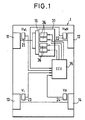
- FIG.1 shows a vehicle 1 provided with a driving wheel slip control device.
- the vehicle 1 is, for example, a front wheel drive type vehicle.
- Two front wheels 11, 12 function as two driving wheels driven by an internal combustion engine,respectively, through a transmission gear while two rear wheels 13, 14 function as two driven wheels, respectively.
- this invention can be adapted for a rear wheel drive type vehicle in the same manner.
- On the driving wheels 11, I2 and the driven wheels 13, 14 are provided two driving wheel velocity sensors 21, 22 (each called a "V W sensor” hereinafter) and two driven wheel velocity (velocity of a vehicle) sensors 23, 24 (each called a "V sensor” hereinafter), respectively.
- the ECU 35 forms a slip detecting means, an engine output reducing means, a prohibition region determining means and a prohibition means.
- the ECU 35 functions to select either the left or right driving wheel velocity V WL or V WR as a driving wheel velocity V W , and to select either the driven wheel velocity V L or V R on the same side as the selected driving wheel velocity V WL or V WR as a vehicle velocity V.
- the ECU 35 controls an output of an engine 31 through a fuel supply control device to adjust each torque of the driving wheels 11, 12 thereby to control a state of slip of the driving wheels 11, 12.
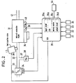
- FIG.2 shows a general construction of the fuel supply control device.
- the internal combustion engine 31 is provided with, for example, six cylinders, and an intake tube 32 is connected on the upstream side of the engine 31 while an exhaust tube 41 is connected on the downstream side thereof, respectively.
- a throttle body 33 At an intermediate portion of the intake tube 32 is provided a throttle body 33 in which a throttle valve 33′ is accommodated.
- the throttle valve 33′ has a sensor 34 for detecting the opening degree of the valve ( ⁇ TH ) which is converted into an electric signal to be sent to the ECU 35.
- a fuel injection valve 36 is provided at an intermediate portion of the intake tube 32 between the engine 31 and the throttle body 33 and at a slightly upstream position of an intake valve (not shown) of each cylinder.
- the fuel injection valve 36 is connected to a fuel pump which is not shown in the drawing and is electrically connected to the ECU 35 so that a period of time for which the valve 36 is opened is controlled.
- an intake tube absolute pressure (P BA ) sensor 38 In contrast, at a downstream position of the throttle body 33 of the intake tube 32 is provided an intake tube absolute pressure (P BA ) sensor 38 through a tube 37, and an absolute pressure signal converted by the absolute pressure sensor 38 into an electric signal is sent to the ECU 35.
- P BA intake tube absolute pressure
- the main body of the engine 31 has an engine cooling water temperature sensor 39 (called a “T W sensor” hereinafter).
- the T W sensor 39 is a thermistor or the like which is inserted into the periphral wall of an engine cylinder to send a detected cooling water temperature signal to the ECU 35.
- An engine revolutional number sensor 40 (called a “Ne sensor” hereinafter is fixed to a peripheral portion of a cam shaft (not shown) of the engine or of a crank-shaft.
- the Ne sensor 40 outputs a crank angle position pulse signals (called a "TDC signal pulse” hereinafter) at predetermined positions at each time when the crank-shaft is rotated through an angle of 120 degrees, that is, at predetermined crank angle positions before each piston reaches the top dead center (TDC) at a time when an intake step of each cylinder starts, and the TDC pulse signal is sent to the ECU 35.
- TDC signal pulse a crank angle position pulse signals
- V W sensors 21, 22, the V sensors 23, 24 and other parameter sensor 44 are connected to the ECU 35 to which each detected signal is sent.
- the ECU 35 shapes input signal waveforms inputted from each sensor to modify a voltage level to a predetermined level and comprises an input circuit 35a functioning to convert an analog signal value into a digital signal value, a central processing unit 35b (called a “CPU” hereinafter), a memory means 35c for memorizing various kind of operational programs and calculated results or the like which are carried out by the CPU 35b, respectively, and an output circuit 35d for sending a driving signal to the fuel injection valve 36.
- CPU central processing unit
- the CPU 35b calculates a fuel injection time of the fuel injection valve 36 in response to engine parameter signals from the various sensors according to the following expression (1) at each time when the TDC pulse signal is put into the CPU 35b.
- T i represents a basic period of time for fuel injection.
- the basic period of time T i is read from a T i map memorized in the memory means 35c in accordance with the intake tube absolute pressure P BA and the engine revolutional number Ne.
- K1 and K2 represent a correction coefficient and a correction variable, respectively, which are determined at respective predetermined values in such a manner that various characteristics such as a characteristic of fuel consumption and a characteristic of acceleration in accordance with the driving state of the engine become optimum.
- the CPU 35b couputs a driving signal for opening tbe fuel injection valve 36 on the basis of the period of time Tout for fuel injection calculated in the above-mentioned manner to the fuel injection valve 36 through the output circuit 5d.
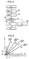
- FIG.3 shows a flow chart of a subroutine for judging whether or not an excessive or abnormal slip has occurred.
- This program is performed at a predetermined interval. First, the driving wheel velocity V W is read from the detected signals of the V W sensors 21, 22 (step 301), and then the vehicle speed V is read from the detected signals of the V sensors 23, 24 (step 302). Thereafter, it is judged whether or not an excessive slip has been generated at the driving wheels 11, 12 (step 303).
- This judgement can be performed in various manners that, for example, the driving wheel velocity V w read in the step 302 is compared with the reference velocity V R calculated on the basis of a predetermined expression in accordance with the vehicle velocity V read in tbe step 302, and that a slip ratio ⁇ calculated on the basis of the driving wheel velocity V W and the vehicle velocity V is compared with a reference slip ratio ⁇ R ( e.g., 15%).
- a slip ratio ⁇ calculated on the basis of the driving wheel velocity V W and the vehicle velocity V is compared with a reference slip ratio ⁇ R ( e.g., 15%).
- FlG. 4 shows a flow chart of a subroutine for controlling fuel supply and suspension of fuel supply. This program is performed synchronously with the TDC pulse signal at each time when the TDC pulse signal is outputted.
- engine parameter signals such as the intake tube absolute pressure P BA , the engine revolutional number Ne and the like inputted from the various sensors are read through a step 401.
- the basic fuel injection time T i of the fuel injection valve 36 is read in response to those engine parameter signals in the above manner (step 402) and the correction coefficient K1 and the correction variable K2 are calculated (step 403).
- fuel injection time Tout is calculated on the basis of the calculated T i K1 and K2 values in accordance with the above expression (step 404).
- step 405 it is determined whether or not flag F TRC is a value "1" (step 405).
- a step 409 starts to output a driving signal on the basis of the fuel injection time Tout calculated through the step 404 to the fuel injection valve 36.
- Tout fuel is supplied from the fuel injection valve 36 to the engine 31 to terminate this program.
- step 40 When the answer of the step 40 is affirmative (Yes), that is, when the flag F TRC is "1", and, accordingly, when an excessive slip has been generated at the driving wheels 11, 12, it is determined in next steps 406, 407 whether or not the engine revolutional number Ne and the vehicle velocity V exist in a region in which a fuel supply to the engine 31 is to be stopped (this is called a "fuel-cut” hereinafter), respectively, in order to prevent reliably an engine stall.
- FIG.5 shows this region.
- four lines II to V show relationships between the engine revolutional number Ne and the vehicle speed V when a slip has not been generated in case that the transmission gear 16 takes four first to fourth gear positions as a parameter, respectively.
- a step 406 it is determined whether or not the engine revolutional number Ne is smaller than a predetermined revolutional number N G .
- the predetermined revolutional number N G is determined on the basis of a solid line I in FIG. 5 in accordance with a vehicle velocity at that time. Namely, a reference velocity V1 (e.g., 30km/h) and a predetermined velocity V G (e.g., 4km/h) smaller than the reference velocity V1 are determined with respect to the vehicle velocity V.
- the predetermined revolutional number N G is determined at a first value N G1 (e.g., 1200rpm) when the vehicle velocity V is larger than the reference velocity V1 and at a second value (e.g., 2000rpm) larger than the first value N G1 when the vehicle velocity V is smaller than the predetermined velocity V G , that is, when the vehicle 1 runs in a low vehicle velocity region, respectively. Further, the predetermined revolutional number N G is determined by an interpolating calculating line I0 when the vehicle velocity V is between the reference velocity V1 and the predetermined velocity V G .
- the reason why the predetermined revolutional number N G is determined according to the vehicle velocity without referring to the driving wheel velocity V W is that an occurrence of an engine stall due to the fuel-out remarkably depends on kinetic energy of a vehicle, and the amount of kinetic energy is reflected by the level of the vehicle velocity V more correctly than other elements.
- step 406 When the answer of the step 406 is negative "No", that is, when the relationship between Ne and N G is Ne ⁇ N G it is determined whether or not the vehicle speed V is smaller than the predetermined vehicle velocity V G (step 407).
- step 409 When the answer is negative "No”, that is, when the relationship between V and V G is V ⁇ V G , the step 409 is performed to terminate this program after the fuel injection time Tout is determined at a value "O" again (step 408).
- the fuel-cut is carried out to reduce the output of the engine, so that an excessive slip of the driving wheels can be prevented.
- the step 409 is performed to terminate this program. That is, even if an excessive slip has been generated at the driving wheels 11, 12, and ,however, if the relationship betwen Ne and N G is Ne ⁇ N G in the case of V > V1, if the relationship between V and V G is V ⁇ V G , and if V and Ne are inside of the interpolating line I0 in the case of V G ⁇ V ⁇ V1 (a region indicated by oblique lines), the fuel-cut is prohibited to supply fuel to the engine in accordance with the fuel injection ime Tout calculated on the basis of the state of driving of the engine 31 in the step 404.
- a fuel-cut region and a fuel-cut prohibition region at a time when an excessive slip has been generated at the driving wheels 11, 12 are determined in the above manner, respectively, when the vehicle runs in a low vehicle velocity condition in which an engine stall is apt to occur, that is, the relationship between V and V G is V ⁇ VG, the fuel-cut operation is prohibited, so that the engine stall can be effectively prevented at that time. Further, when the vehicle 1 runs in a low vehicle velocity condition, the predetermined revolutional number N G is determined at a large value in the above manner, and accordingly, the resonance phenomenon of the suspension system can be prevented.
- the prohibiting operation of the fuel-cut in case that the transmission gear takes a high gear shift position such as a third or fourth gear shift position, etc. can be performed on a larger engine revolutional number side in comparison with a fuel-cut prohibition region determined according to only the vehicle velocity V (see FIG.5), and accordingly, an occurrence of an engine stall can be reliably prevented.
- the possibility of the ocurrence of the engine stall due to the fuel-cut is rather low in intermediate and high velocity conditions of the vehicle 1, and accordingly, even if the predetermined revolutional number N G is determined at a smaller value as mentioned above, the engine stall is not caused by the determination.
- Such a determination expands a fuel-cut region, namely, a slip control region thereby to prevent an excessive slip in the region.
- the output of the engine is decreased by suspension of fuel supply to the engine in this embodiment, and, however, the method of decreasing the output of the engine may be a method in which ingnition is stopped in addition to the above method.
- a driving wheel slip control device comprises a prohibition region determining means for determining a control prohibition region on the basis of velocity of a vehicle and number of revolutions of an engine, and a prohibition means for prohibiting an engine output reducing means from operating so as to reduce an output of the engine in response to the output from a slip detecting means for detecting the state of slip of the driving wheels, a resnonance phenomenon in a suspension system can be prevented to improve a driving ability, and prevention of an engine stall as well as expansion of a slip control region can be realized.
- a driving wheel slip control device has a prohibition region determining means (35) for determining a prohibition region in which an engine control operation such as a fuel-cut operation or a ignition stop operation is carried our, and a prohibition means (35) for prohibiting the engine control operation even if an excessive or abnormal slip is generated whereby preventions of a ressonance and an engine stall are realized in addition to an expansion of a slip control region.
Landscapes
- Engineering & Computer Science (AREA)
- Chemical & Material Sciences (AREA)
- Combustion & Propulsion (AREA)
- Transportation (AREA)
- Mechanical Engineering (AREA)
- Control Of Vehicle Engines Or Engines For Specific Uses (AREA)
- Electrical Control Of Air Or Fuel Supplied To Internal-Combustion Engine (AREA)
- Auxiliary Drives, Propulsion Controls, And Safety Devices (AREA)
Applications Claiming Priority (2)
| Application Number | Priority Date | Filing Date | Title |
|---|---|---|---|
| JP314589/87 | 1987-12-10 | ||
| JP62314589A JPH01155038A (ja) | 1987-12-10 | 1987-12-10 | 駆動輪スリップ制御装置 |
Publications (3)
| Publication Number | Publication Date |
|---|---|
| EP0320007A2 true EP0320007A2 (fr) | 1989-06-14 |
| EP0320007A3 EP0320007A3 (en) | 1990-03-21 |
| EP0320007B1 EP0320007B1 (fr) | 1993-09-08 |
Family
ID=18055115
Family Applications (1)
| Application Number | Title | Priority Date | Filing Date |
|---|---|---|---|
| EP88120641A Expired - Lifetime EP0320007B1 (fr) | 1987-12-10 | 1988-12-09 | Dispositif de commande de glissement d'une roue motrice |
Country Status (4)
| Country | Link |
|---|---|
| US (1) | US4959794A (fr) |
| EP (1) | EP0320007B1 (fr) |
| JP (1) | JPH01155038A (fr) |
| DE (1) | DE3883938T2 (fr) |
Cited By (2)
| Publication number | Priority date | Publication date | Assignee | Title |
|---|---|---|---|---|
| EP0477940A2 (fr) * | 1990-09-28 | 1992-04-01 | Mazda Motor Corporation | Système de commande du couple d'un moteur de véhicule |
| EP0575920A1 (fr) * | 1992-06-22 | 1993-12-29 | Toyota Jidosha Kabushiki Kaisha | Dispositif de commande de traction dans lequel la force d'entraînement est augmentée lorsqu'une condition de calage est detectée |
Families Citing this family (9)
| Publication number | Priority date | Publication date | Assignee | Title |
|---|---|---|---|---|
| DE3634240A1 (de) * | 1986-10-08 | 1988-04-21 | Bosch Gmbh Robert | Antriebsschlupfregeleinrichtung |
| JPH02245433A (ja) * | 1989-03-17 | 1990-10-01 | Toyota Motor Corp | 車両の加速スリップ制御装置 |
| US5042436A (en) * | 1989-04-19 | 1991-08-27 | Honda Giken Kogyo Kabushiki Kaisha | Valve control system for internal combustion engines |
| US5046461A (en) * | 1989-04-19 | 1991-09-10 | Honda Giken Kogyo Kabushiki Kaisha | Valve control system for internal combustion engines |
| JPH0333441A (ja) * | 1989-06-29 | 1991-02-13 | Mazda Motor Corp | 車両のスリップ制御装置 |
| GB9100224D0 (en) * | 1991-01-05 | 1991-02-20 | Lucas Ind Plc | Method of and apparatus for controlling wheel spin |
| JP2606522Y2 (ja) * | 1992-05-20 | 2000-11-27 | 三菱自動車工業株式会社 | トラクションコントロールの制御切り換え装置 |
| US5583989A (en) * | 1992-05-28 | 1996-12-10 | Honda Giken Kogyo Kabushiki Kaisha | Vehicle control system having program generator and convertor |
| JPH07166906A (ja) * | 1993-12-14 | 1995-06-27 | Nissan Motor Co Ltd | 燃料カットと点火時期変更による加速スリップ制御装置 |
Citations (4)
| Publication number | Priority date | Publication date | Assignee | Title |
|---|---|---|---|---|
| US3680655A (en) * | 1970-07-06 | 1972-08-01 | Gen Motors Corp | Electrical wheel slip limiting apparatus |
| EP0163941A1 (fr) * | 1984-05-03 | 1985-12-11 | Robert Bosch Gmbh | Circuit de régulation pour les roues motrices d'un véhicule |
| JPS611543A (ja) * | 1984-06-12 | 1986-01-07 | Toyota Motor Corp | 車両の加速スリツプ防止方法 |
| EP0240174A1 (fr) * | 1986-03-04 | 1987-10-07 | Honda Giken Kogyo Kabushiki Kaisha | Système de régulation de la traction pour contrôler le patinage d'une roue motrice d'un véhicule |
Family Cites Families (7)
| Publication number | Priority date | Publication date | Assignee | Title |
|---|---|---|---|---|
| DE3545652A1 (de) * | 1985-12-21 | 1987-06-25 | Daimler Benz Ag | Einrichtung zur vortriebsregelung an kraftfahrzeugen |
| DE3545717A1 (de) * | 1985-12-21 | 1987-06-25 | Daimler Benz Ag | Einrichtung zur vortriebsregelung an kraftfahrzeugen |
| JPS62157851A (ja) * | 1985-12-28 | 1987-07-13 | Toyota Motor Corp | 加速スリツプ制御装置 |
| JPH0620877B2 (ja) * | 1986-04-23 | 1994-03-23 | トヨタ自動車株式会社 | 車両の加速スリツプ制御方法 |
| CA1306784C (fr) * | 1986-06-09 | 1992-08-25 | Masakazu Sakaguchi | Methode permettant de reduire le patinage des roues motrices d'un vehicule |
| DE3784577T2 (de) * | 1986-07-24 | 1993-06-17 | Mazda Motor | Fahrzeug-schleuder-steuervorrichtung. |
| DE3728573C1 (de) * | 1987-08-27 | 1988-11-24 | Daimler Benz Ag | Einrichtung zum Regeln wenigstens einer das Antriebsmoment einer Brennkraftmaschine eines Kraftfahrzeuges beeinflussenden Groesse |
-
1987
- 1987-12-10 JP JP62314589A patent/JPH01155038A/ja active Pending
-
1988
- 1988-12-05 US US07/279,693 patent/US4959794A/en not_active Expired - Lifetime
- 1988-12-09 DE DE88120641T patent/DE3883938T2/de not_active Expired - Lifetime
- 1988-12-09 EP EP88120641A patent/EP0320007B1/fr not_active Expired - Lifetime
Patent Citations (4)
| Publication number | Priority date | Publication date | Assignee | Title |
|---|---|---|---|---|
| US3680655A (en) * | 1970-07-06 | 1972-08-01 | Gen Motors Corp | Electrical wheel slip limiting apparatus |
| EP0163941A1 (fr) * | 1984-05-03 | 1985-12-11 | Robert Bosch Gmbh | Circuit de régulation pour les roues motrices d'un véhicule |
| JPS611543A (ja) * | 1984-06-12 | 1986-01-07 | Toyota Motor Corp | 車両の加速スリツプ防止方法 |
| EP0240174A1 (fr) * | 1986-03-04 | 1987-10-07 | Honda Giken Kogyo Kabushiki Kaisha | Système de régulation de la traction pour contrôler le patinage d'une roue motrice d'un véhicule |
Non-Patent Citations (1)
| Title |
|---|
| PATENT ABSTRACTS OF JAPAN Vol. 10, No. 146 (M-482)(2203) 28 May 1986,& JP-A-61 001 543 (TOYOTA) 07 January 1986, * |
Cited By (4)
| Publication number | Priority date | Publication date | Assignee | Title |
|---|---|---|---|---|
| EP0477940A2 (fr) * | 1990-09-28 | 1992-04-01 | Mazda Motor Corporation | Système de commande du couple d'un moteur de véhicule |
| EP0477940A3 (en) * | 1990-09-28 | 1993-01-27 | Mazda Motor Corporation | Engine output control system for vehicle |
| EP0575920A1 (fr) * | 1992-06-22 | 1993-12-29 | Toyota Jidosha Kabushiki Kaisha | Dispositif de commande de traction dans lequel la force d'entraînement est augmentée lorsqu'une condition de calage est detectée |
| US5459661A (en) * | 1992-06-22 | 1995-10-17 | Toyota Jidosha Kabushiki Kaisha | Traction control apparatus in which a driving force is increased when a stalling condition is detected |
Also Published As
| Publication number | Publication date |
|---|---|
| EP0320007B1 (fr) | 1993-09-08 |
| EP0320007A3 (en) | 1990-03-21 |
| DE3883938T2 (de) | 1994-02-03 |
| US4959794A (en) | 1990-09-25 |
| JPH01155038A (ja) | 1989-06-16 |
| DE3883938D1 (de) | 1993-10-14 |
Similar Documents
| Publication | Publication Date | Title |
|---|---|---|
| US4638781A (en) | Fuel cut-off device for internal combustion engine | |
| US5099942A (en) | Traction control device for a vehicle | |
| US4596164A (en) | Air-fuel ratio control method for internal combustion engines for vehicles | |
| US4921064A (en) | Driving wheel slip control system for vehicles | |
| US5038883A (en) | Traction control device for a vehicle | |
| US4491115A (en) | Method for controlling fuel supply to an internal combustion engine at deceleration | |
| EP0298232A2 (fr) | Système de commande de glissement pour roues motrices pour véhicules | |
| EP0320007B1 (fr) | Dispositif de commande de glissement d'une roue motrice | |
| US4508088A (en) | Method for controlling fuel supply to an internal combustion engine after termination of fuel cut | |
| US4621600A (en) | Fuel supply control method for internal combustion engines at fuel cut operation | |
| US5411000A (en) | Ignition timing control system for internal combustion engine | |
| EP0334371B1 (fr) | Système de commande de patinage de roue motrice pour véhicule | |
| JPH0826837B2 (ja) | 内燃エンジンの点火時期制御装置 | |
| JPH0575896B2 (fr) | ||
| JP2871270B2 (ja) | 坂路推定方法 | |
| US4736719A (en) | System for limiting the maximum speed of an internal combustion engine comprising an electronic injection system | |
| EP0334370A2 (fr) | Appareil de commande de patinage excessif de roue motrice | |
| US6325741B1 (en) | Throttle valve control apparatus and method for internal combustion engine | |
| US5661974A (en) | Control system with function of protecting catalytic converter for internal combustion engines for vehicles | |
| US4987874A (en) | Control system for controlling spark timing of engine | |
| JP4103547B2 (ja) | 内燃機関出力制御方法及び装置 | |
| JPH11351112A (ja) | 車載内燃エンジンの点火時期制御装置 | |
| JPS61160538A (ja) | 車両の加速スリツプ制御装置 | |
| JPH0763109A (ja) | エンジンの点火装置 | |
| JPH0545253A (ja) | 多気筒内燃機関の失火検出装置 |
Legal Events
| Date | Code | Title | Description |
|---|---|---|---|
| PUAI | Public reference made under article 153(3) epc to a published international application that has entered the european phase |
Free format text: ORIGINAL CODE: 0009012 |
|
| AK | Designated contracting states |
Kind code of ref document: A2 Designated state(s): DE FR GB SE |
|
| PUAL | Search report despatched |
Free format text: ORIGINAL CODE: 0009013 |
|
| AK | Designated contracting states |
Kind code of ref document: A3 Designated state(s): DE FR GB SE |
|
| 17P | Request for examination filed |
Effective date: 19900705 |
|
| 17Q | First examination report despatched |
Effective date: 19920519 |
|
| GRAA | (expected) grant |
Free format text: ORIGINAL CODE: 0009210 |
|
| AK | Designated contracting states |
Kind code of ref document: B1 Designated state(s): DE FR GB SE |
|
| PG25 | Lapsed in a contracting state [announced via postgrant information from national office to epo] |
Ref country code: SE Effective date: 19930908 Ref country code: FR Effective date: 19930908 |
|
| REF | Corresponds to: |
Ref document number: 3883938 Country of ref document: DE Date of ref document: 19931014 |
|
| EN | Fr: translation not filed | ||
| PLBE | No opposition filed within time limit |
Free format text: ORIGINAL CODE: 0009261 |
|
| STAA | Information on the status of an ep patent application or granted ep patent |
Free format text: STATUS: NO OPPOSITION FILED WITHIN TIME LIMIT |
|
| 26N | No opposition filed | ||
| REG | Reference to a national code |
Ref country code: GB Ref legal event code: IF02 |
|
| PGFP | Annual fee paid to national office [announced via postgrant information from national office to epo] |
Ref country code: GB Payment date: 20031203 Year of fee payment: 16 |
|
| PG25 | Lapsed in a contracting state [announced via postgrant information from national office to epo] |
Ref country code: GB Free format text: LAPSE BECAUSE OF NON-PAYMENT OF DUE FEES Effective date: 20041209 |
|
| GBPC | Gb: european patent ceased through non-payment of renewal fee |
Effective date: 20041209 |
|
| PGFP | Annual fee paid to national office [announced via postgrant information from national office to epo] |
Ref country code: DE Payment date: 20071206 Year of fee payment: 20 |