EP0319731B1 - Tour à poupée déplaçable axialement - Google Patents
Tour à poupée déplaçable axialement Download PDFInfo
- Publication number
- EP0319731B1 EP0319731B1 EP88118810A EP88118810A EP0319731B1 EP 0319731 B1 EP0319731 B1 EP 0319731B1 EP 88118810 A EP88118810 A EP 88118810A EP 88118810 A EP88118810 A EP 88118810A EP 0319731 B1 EP0319731 B1 EP 0319731B1
- Authority
- EP
- European Patent Office
- Prior art keywords
- guideways
- bed
- machine bed
- lathe
- headstock
- Prior art date
- Legal status (The legal status is an assumption and is not a legal conclusion. Google has not performed a legal analysis and makes no representation as to the accuracy of the status listed.)
- Expired - Lifetime
Links
- 230000000712 assembly Effects 0.000 claims 1
- 238000000429 assembly Methods 0.000 claims 1
- 238000003754 machining Methods 0.000 description 8
- 238000010276 construction Methods 0.000 description 2
- 238000005553 drilling Methods 0.000 description 2
- 238000003801 milling Methods 0.000 description 2
- 238000000926 separation method Methods 0.000 description 2
- 238000006073 displacement reaction Methods 0.000 description 1
- 230000001771 impaired effect Effects 0.000 description 1
Images


Classifications
-
- B—PERFORMING OPERATIONS; TRANSPORTING
- B23—MACHINE TOOLS; METAL-WORKING NOT OTHERWISE PROVIDED FOR
- B23Q—DETAILS, COMPONENTS, OR ACCESSORIES FOR MACHINE TOOLS, e.g. ARRANGEMENTS FOR COPYING OR CONTROLLING; MACHINE TOOLS IN GENERAL CHARACTERISED BY THE CONSTRUCTION OF PARTICULAR DETAILS OR COMPONENTS; COMBINATIONS OR ASSOCIATIONS OF METAL-WORKING MACHINES, NOT DIRECTED TO A PARTICULAR RESULT
- B23Q1/00—Members which are comprised in the general build-up of a form of machine, particularly relatively large fixed members
- B23Q1/01—Frames, beds, pillars or like members; Arrangement of ways
- B23Q1/017—Arrangements of ways
-
- B—PERFORMING OPERATIONS; TRANSPORTING
- B23—MACHINE TOOLS; METAL-WORKING NOT OTHERWISE PROVIDED FOR
- B23B—TURNING; BORING
- B23B3/00—General-purpose turning-machines or devices, e.g. centre lathes with feed rod and lead screw; Sets of turning-machines
- B23B3/06—Turning-machines or devices characterised only by the special arrangement of constructional units
-
- B—PERFORMING OPERATIONS; TRANSPORTING
- B23—MACHINE TOOLS; METAL-WORKING NOT OTHERWISE PROVIDED FOR
- B23Q—DETAILS, COMPONENTS, OR ACCESSORIES FOR MACHINE TOOLS, e.g. ARRANGEMENTS FOR COPYING OR CONTROLLING; MACHINE TOOLS IN GENERAL CHARACTERISED BY THE CONSTRUCTION OF PARTICULAR DETAILS OR COMPONENTS; COMBINATIONS OR ASSOCIATIONS OF METAL-WORKING MACHINES, NOT DIRECTED TO A PARTICULAR RESULT
- B23Q1/00—Members which are comprised in the general build-up of a form of machine, particularly relatively large fixed members
- B23Q1/01—Frames, beds, pillars or like members; Arrangement of ways
Definitions
- the invention relates to a lathe with a machine bed, with at least one headstock axially displaceable on the horizontal top of the machine bed, in which a workpiece spindle is rotatably mounted, with at least one bed slide displaceable transversely to the workpiece spindle, the horizontally running guideways of which are arranged on a vertical surface of the machine bed are and which in turn has a guideway which extends transversely to the guideway of the bed carriage and transversely to the workpiece spindle axis in a vertical plane and on which a tool slide is arranged.
- Such a lathe is known from DE-OS 20 62 668, the spindle of which is mounted in an axially displaceable headstock and which is equipped with a clamping element holding a workpiece.
- a tool acts on this workpiece and can be moved in a plane perpendicular to the direction of the spindle axis.
- the machine bed which has the guide for the headstock and for a cross slide, is designed cranked, so that there is a widely protruding frame. Nevertheless, only relatively short workpieces can be machined because only the height of the cantilevered top slide, which can be moved transversely to the feed direction of the headstock and the cross slide, and the tool carrier height for the longitudinal machining of the workpiece are available. The machine is therefore not suitable for bar parts.
- a lathe is also known from DE-OS 25 26 343, in which the spindle is designed as a quill which can be axially displaced in the headstock.
- a horizontal guide for a tool slide is provided on the face of the headstock.
- the headstock is also intended to form the machine frame.
- the design of the workpiece spindle as a quill severely limits the possibility of variation in the machine configuration based on this basic unit and limits the performance of the workpiece spindle drive.
- JP-A 61-86103 shows a lathe with a cuboid base unit as a machine bed, which has guide tracks for a tool turret on its upper side and guide tracks for an axially displaceable headstock on its front side. Even for the collision-free switching movement of the tool turret, a trough must be provided below the turret for this machine. A feed movement in a direction perpendicular to the spindle axis and to the tool turret axis is not provided. The arrangement also offers no space for them.
- the invention has for its object not to affect the working space in a lathe of the type mentioned, with relative movements between the tool and workpiece in three linear directions perpendicular to each other, and to allow a large stroke for the tool slide.
- the shape of the basic unit and the arrangement of the guideways enable a large stroke for the tool slide, the stroke of the headstock also not being limited thereby.
- the headstock is a relatively heavy structural unit, especially when the drive power is high.
- the introduction of the forces into the base unit and the loading of the guide surfaces is therefore more advantageous with guide tracks arranged on the top of the base unit than with those arranged on the end face.
- the claimed lathe with the machine bed is very rigid, firstly because the cuboid base unit is a very torsionally rigid and compact construction that can also be easily ribbed, and secondly because there is only one parting plane between the headstock and the base unit, between the tool holder and the base unit there are no more than two separation levels. Constructions in which the feed movement in three mutually perpendicular directions are only carried out by the tool must master three separation points in a component without play, which leads to a loss of rigidity.
- the basic unit can also form the basis for a two-spindle lathe. In this case, two guideways must be provided across the guideway for the bed slides. This arrangement also results if the proposed basic unit is combined with a second mirror-image basic unit.
- the guideway of the bed slide must extend approximately the same length on both sides of the headstock guide, so that in each case on opposite sides of the workpiece spindle or of the work to be machined one bed sledge can be guided each.
- the tool carrier for turning tools e.g. B. a tool turret
- the second bed carriage carries the displaceable tool carriage on which preferably rotatingly driven tools can be arranged.
- the cuboid shape of the basic unit forms flat surfaces on the upper side, which can be used to fasten tool and / or workpiece changing devices.
- the basic unit with a guideway on the top for the sliding headstock, a parallel guideway on one end face and the guideway pair perpendicular to these two guideways also offers the possibility of arranging a counter spindle on an additional bed slide, which allows the back machining of a workpiece pre-machined in the workpiece spindle allowed.
- a tool carrier is provided on the second guideway running parallel to the headstock guideway. The workpiece is compared to this tool carrier by a transverse displacement of the bed slide with the counter spindle.
- the machine bed 1 shows a simple embodiment of a lathe with the machine bed according to the invention in plan view.
- the machine bed 1 has two pairs of guideways 2, 3, 4 for the displaceable headstock 5 and the bed slide 6.
- the rotary spindle 7 is mounted, to which a chuck 8 is fastened.
- the chuck 8 carries the workpiece 9 that is to be machined.
- the rotating spindle 7 is driven in rotation by the motor 10.
- the headstock 5 is moved together with the chuck 8, the workpiece 9 and the motor 10 on the guides 2, 3 by the feed motor 11.
- the pair of guideways 4, of which only the upper guide 12 can be seen, is arranged transversely to the direction of the guideways 2, 3 of the headstock 5.
- a bed carriage 6 is moved on the pair of guideways 4 by the feed motor 13.
- the bed slide 6 in turn carries a tool slide 14 which can be moved relative to the bed slide 6 by the feed motor 15.
- the space in front of the pair of guideways 4 perpendicular to the plane of the drawing up to the surface of the lathe is completely free, so that sufficiently long guides can be accommodated for the tool slide 14 without the working space being impaired.
- On the tool slide 14 is a tool carrier, for. B.
- a tool turret 16 is attached, which carries a turret disk 17 on the side facing the workpiece 9.
- the machining tools are clamped in the turret disk 17. Of them, only one external turning tool 18 and one internal machining tool 19 are shown here.
- the internal machining tool 19 can be driven in rotation by a drive motor 20.
- the pair of guideways 2, 3 of the headstock 5 and the pair of guideways 4 for the bed slide 6 form an angle in which a clamping surface 21 is formed by the cuboid shape of the machine bed 1. This clamping surface 21 can be used for the arrangement of tool and workpiece changing devices, not shown here.
- the headstock carries out the feed in the Z direction
- the bed slide carries out the feed in the X direction
- the tool slide carries out the feed in the Y direction. This enables versatile machining on the workpiece without restricting the working space.
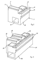
- Fig. 2 shows the machine bed 1 in a perspective view without superstructures.
- the guides 12, 23, which belong to the pair of guideways 4 of the bed slide 6, can be seen on the base unit 22.
- the guide 12 lies vertically above the guide 23.
- the guide tracks 2, 3 of the headstock 5 are arranged transversely to the guides 12, 23 on the upper side of the base unit 22.
- a chip conveyor is inserted into the chip tunnel 25.
- the chip chute can be kept relatively narrow because the workpiece is only machined in a vertical plane.
- FIG. 3 shows the bed slide 6 with its guide profile 26 and the pressure strips 27, 28.
- the bed slide 6 carries guideways 29 for the tool slide 14.
- the housing 30 of the tool turret 16 is arranged on the tool slide 14, the turret disk 17 of which has an axis parallel to the headstock guide.
- turrets with a different axis orientation can also be arranged on the horizontal leg of the tool slide 14.
- the cuboid base unit 32 thus has an elongated shape.
- the basic structure of the guideways for the headstocks 5 and bed slide 6 does not change.
- On the top of the base unit 32 two pairs of guideways 33, 34 for two headstocks 5 are arranged, while on the front side of the base unit 32 a pair of guideways 35 is provided, on which two bed slides 6 with the appropriate equipment can be moved.
- Each bed slide 6 is assigned to a headstock 5.
- a clamping surface 36, 37 results between each pair of guideways 33, 34 for a headstock 5 and pair of guideways 35 for the bed slide.
- the machine bed 31 can also be produced by assembling a basic unit according to FIG. 2 with its mirror-image design. However, this results in a parting line 38, which is indicated by dashed lines in FIG. 4.
- the basic unit 39 according to FIG. 5 corresponds to that of FIG. 4 with the exception of only one pair of guideways 40 for only one headstock 5.
- Two bed slides 6 can be arranged on the slide guides, one of which preferably the turning tools and the other the driven drilling tool. and milling tools because the feed movement of the workpiece limits simultaneous machining to special cases. In this case, only the bed slide for the drilling and milling tools needs to be equipped with a tool slide that can be moved in the Y direction.
- the machine bed shown in Fig. 6 is intended for a lathe with a counter spindle for backside machining.
- a pair of guideways 43 is attached to a further end face of the base unit 22, which runs parallel to the guides 44, 45 of the headstock 5.
- Another ribbed chip shaft 46 is accommodated between the guide 45 and the pair of guideways 43.
- a further slide is arranged on the pair of guideways 42, which carries a driven workpiece spindle as a counter spindle.
- a third bed slide 6 is built, the tools of which are directed towards the counter spindle.
Landscapes
- Engineering & Computer Science (AREA)
- Mechanical Engineering (AREA)
- Turning (AREA)
Claims (6)
Applications Claiming Priority (2)
| Application Number | Priority Date | Filing Date | Title |
|---|---|---|---|
| DE19873742042 DE3742042C1 (de) | 1987-12-11 | 1987-12-11 | Maschinenbett fuer eine Drehmaschine mit axial verschiebbarem Spindelstock |
| DE3742042 | 1987-12-11 |
Publications (3)
| Publication Number | Publication Date |
|---|---|
| EP0319731A2 EP0319731A2 (fr) | 1989-06-14 |
| EP0319731A3 EP0319731A3 (en) | 1990-02-28 |
| EP0319731B1 true EP0319731B1 (fr) | 1992-07-08 |
Family
ID=6342387
Family Applications (1)
| Application Number | Title | Priority Date | Filing Date |
|---|---|---|---|
| EP88118810A Expired - Lifetime EP0319731B1 (fr) | 1987-12-11 | 1988-11-11 | Tour à poupée déplaçable axialement |
Country Status (2)
| Country | Link |
|---|---|
| EP (1) | EP0319731B1 (fr) |
| DE (1) | DE3742042C1 (fr) |
Families Citing this family (5)
| Publication number | Priority date | Publication date | Assignee | Title |
|---|---|---|---|---|
| DE19825523A1 (de) * | 1998-06-08 | 1999-12-16 | Ilg Gmbh | Werkzeugmaschine |
| DE19932645C5 (de) * | 1999-07-13 | 2007-01-11 | Agie S.A., Losone | Funkenerosionsmaschine und Modulsatz für den Zusammenbau von Werkzeugmaschinen, insbesondere Funkenerosionsmaschinen |
| JP2001315032A (ja) | 2000-05-08 | 2001-11-13 | Mori Seiki Co Ltd | 工作機械 |
| JP2002096202A (ja) * | 2000-09-18 | 2002-04-02 | Mori Seiki Co Ltd | 工作機械の主軸台案内装置 |
| WO2014150802A1 (fr) * | 2013-03-15 | 2014-09-25 | Microlution Inc. | Machine à tourner micro |
Family Cites Families (11)
| Publication number | Priority date | Publication date | Assignee | Title |
|---|---|---|---|---|
| CH94154A (fr) * | 1919-06-16 | 1922-04-17 | Tornos Sa Fabrique De Machine | Bascule avec porte-outils pour machines à décolleter. |
| US3726162A (en) * | 1969-12-27 | 1973-04-10 | Nippon Seiko Kk | Numerically controlled lathe |
| DE2526343A1 (de) * | 1975-06-12 | 1976-12-16 | Index Werke Kg Hahn & Tessky | Revolver-drehautomat |
| IL60089A0 (en) * | 1980-05-16 | 1980-07-31 | Israel Nachmany | Improvements relating to the structure of automatic machine tools |
| JPS57189748A (en) * | 1981-05-13 | 1982-11-22 | Tsugami Corp | Horizontal machining center |
| JPS60207746A (ja) * | 1984-03-30 | 1985-10-19 | Washino Koki Kk | 多面加工機械 |
| DE3418124A1 (de) * | 1984-05-16 | 1985-11-21 | Mauser-Werke Oberndorf Gmbh, 7238 Oberndorf | Bearbeitungszentrum |
| JPS6186103A (ja) * | 1984-10-04 | 1986-05-01 | Citizen Watch Co Ltd | 自動施盤 |
| EP0226836B1 (fr) * | 1985-11-26 | 1990-05-23 | Citizen Watch Co. Ltd. | Machine à commande numérique |
| JPS63162101A (ja) * | 1986-12-26 | 1988-07-05 | Okuma Mach Works Ltd | ユニツト構成nc旋盤及び加工セル |
| JPH06186103A (ja) * | 1992-12-21 | 1994-07-08 | Taisee:Kk | センサー端子切替手段、並びに磁気測定方法若しくは圧力測定方法 |
-
1987
- 1987-12-11 DE DE19873742042 patent/DE3742042C1/de not_active Expired
-
1988
- 1988-11-11 EP EP88118810A patent/EP0319731B1/fr not_active Expired - Lifetime
Non-Patent Citations (2)
| Title |
|---|
| PATENT ABSTRACTS OF JAPAN Band 10, Nr. 261 (M-514)(2317), 5 September 1986 ; & JP - A - 6186103 (CITIZEN WATCH LTD). * |
| PATENT ABSTRACTS OF JAPAN Band 12, Nr. 428 (M-762)(3275), 11 November 1988 & JP - A - 63162101 (OKUMA MACH WORKS LTD). * |
Also Published As
| Publication number | Publication date |
|---|---|
| EP0319731A3 (en) | 1990-02-28 |
| DE3742042C1 (de) | 1989-06-01 |
| EP0319731A2 (fr) | 1989-06-14 |
Similar Documents
| Publication | Publication Date | Title |
|---|---|---|
| DE68909889T2 (de) | Werkzeugmaschine für mehrere bearbeitungsarten und zur komplexen bearbeitung von langen werkstücken. | |
| DE3035451C2 (fr) | ||
| EP2255907B1 (fr) | Machine-outil et procédé destiné au traitement par enlèvement de copeaux de pièces usinées, en particulier de pièces usinées métalliques | |
| EP0999002B1 (fr) | Tour avec broche additionelle | |
| EP1118428B1 (fr) | Tour | |
| DE2523751A1 (de) | Mehrspindelwerkzeugmaschine | |
| DE3410276C2 (fr) | ||
| EP1409182B1 (fr) | Machine-outil | |
| DE3420531C2 (de) | Drehautomat | |
| DE19919645A1 (de) | Werkzeugmaschine mit Werkzeugspindel und Revolverkopf | |
| DE4015570A1 (de) | Werkzeugmaschine, insbesondere vertikal-schleifmaschine und verfahren zum bearbeiten von werkstuecken mit dieser maschine | |
| EP0585690A1 (fr) | Tour | |
| EP0953403B1 (fr) | Machine-outil | |
| DE3921649C2 (de) | Maschinenbett mit Überhang | |
| DE69012585T2 (de) | Drehautomat mit unbeweglichem spindelstock und aufbearbeitungsspindel. | |
| EP0319731B1 (fr) | Tour à poupée déplaçable axialement | |
| EP0097271B1 (fr) | Machine à fraiser des vilebrequins | |
| DE2636986C3 (de) | Drehmaschine | |
| EP2036638A1 (fr) | Dispositif de traitement en particulier de grands diamètres d'une pièce à usiner | |
| EP1074333B1 (fr) | Tour avec deux systèmes de support d'outils | |
| DE10139296B4 (de) | Spannvorrichtung für mehrseitig zu bearbeitende Werkstücke | |
| DE4330858C1 (de) | Verfahren zum Bearbeiten eines Werkstückes auf einem CNC-Drehautomaten sowie CNC-Drehautomat | |
| DE3824572C2 (fr) | ||
| DE3842190A1 (de) | Drehmaschine | |
| DE3530982A1 (de) | Zweispindlige, numerisch gesteuerte drehmaschine |
Legal Events
| Date | Code | Title | Description |
|---|---|---|---|
| PUAI | Public reference made under article 153(3) epc to a published international application that has entered the european phase |
Free format text: ORIGINAL CODE: 0009012 |
|
| AK | Designated contracting states |
Kind code of ref document: A2 Designated state(s): CH FR GB IT LI SE |
|
| PUAL | Search report despatched |
Free format text: ORIGINAL CODE: 0009013 |
|
| AK | Designated contracting states |
Kind code of ref document: A3 Designated state(s): CH FR GB IT LI SE |
|
| 17P | Request for examination filed |
Effective date: 19900315 |
|
| 17Q | First examination report despatched |
Effective date: 19910201 |
|
| GRAA | (expected) grant |
Free format text: ORIGINAL CODE: 0009210 |
|
| AK | Designated contracting states |
Kind code of ref document: B1 Designated state(s): CH FR GB IT LI SE |
|
| ITF | It: translation for a ep patent filed | ||
| GBT | Gb: translation of ep patent filed (gb section 77(6)(a)/1977) | ||
| ET | Fr: translation filed | ||
| PLBE | No opposition filed within time limit |
Free format text: ORIGINAL CODE: 0009261 |
|
| STAA | Information on the status of an ep patent application or granted ep patent |
Free format text: STATUS: NO OPPOSITION FILED WITHIN TIME LIMIT |
|
| 26N | No opposition filed | ||
| PGFP | Annual fee paid to national office [announced via postgrant information from national office to epo] |
Ref country code: SE Payment date: 19931013 Year of fee payment: 6 Ref country code: FR Payment date: 19931013 Year of fee payment: 6 |
|
| PGFP | Annual fee paid to national office [announced via postgrant information from national office to epo] |
Ref country code: CH Payment date: 19931018 Year of fee payment: 6 |
|
| PGFP | Annual fee paid to national office [announced via postgrant information from national office to epo] |
Ref country code: GB Payment date: 19931110 Year of fee payment: 6 |
|
| PG25 | Lapsed in a contracting state [announced via postgrant information from national office to epo] |
Ref country code: GB Effective date: 19941111 |
|
| PG25 | Lapsed in a contracting state [announced via postgrant information from national office to epo] |
Ref country code: SE Effective date: 19941112 |
|
| PG25 | Lapsed in a contracting state [announced via postgrant information from national office to epo] |
Ref country code: LI Effective date: 19941130 Ref country code: CH Effective date: 19941130 |
|
| EAL | Se: european patent in force in sweden |
Ref document number: 88118810.6 |
|
| GBPC | Gb: european patent ceased through non-payment of renewal fee |
Effective date: 19941111 |
|
| PG25 | Lapsed in a contracting state [announced via postgrant information from national office to epo] |
Ref country code: FR Effective date: 19950731 |
|
| REG | Reference to a national code |
Ref country code: CH Ref legal event code: PL |
|
| EUG | Se: european patent has lapsed |
Ref document number: 88118810.6 |
|
| REG | Reference to a national code |
Ref country code: FR Ref legal event code: ST |
|
| PG25 | Lapsed in a contracting state [announced via postgrant information from national office to epo] |
Ref country code: IT Free format text: LAPSE BECAUSE OF NON-PAYMENT OF DUE FEES;WARNING: LAPSES OF ITALIAN PATENTS WITH EFFECTIVE DATE BEFORE 2007 MAY HAVE OCCURRED AT ANY TIME BEFORE 2007. THE CORRECT EFFECTIVE DATE MAY BE DIFFERENT FROM THE ONE RECORDED. Effective date: 20051111 |