EP0319357B1 - Ranchabzugs- oder analoge Dachöffnung mit grossen Öffnungsweg des Schlussdeckels - Google Patents
Ranchabzugs- oder analoge Dachöffnung mit grossen Öffnungsweg des Schlussdeckels Download PDFInfo
- Publication number
- EP0319357B1 EP0319357B1 EP88402818A EP88402818A EP0319357B1 EP 0319357 B1 EP0319357 B1 EP 0319357B1 EP 88402818 A EP88402818 A EP 88402818A EP 88402818 A EP88402818 A EP 88402818A EP 0319357 B1 EP0319357 B1 EP 0319357B1
- Authority
- EP
- European Patent Office
- Prior art keywords
- panel
- opening
- box
- articulated
- frame
- Prior art date
- Legal status (The legal status is an assumption and is not a legal conclusion. Google has not performed a legal analysis and makes no representation as to the accuracy of the status listed.)
- Expired - Lifetime
Links
Images

Classifications
-
- F—MECHANICAL ENGINEERING; LIGHTING; HEATING; WEAPONS; BLASTING
- F24—HEATING; RANGES; VENTILATING
- F24F—AIR-CONDITIONING; AIR-HUMIDIFICATION; VENTILATION; USE OF AIR CURRENTS FOR SCREENING
- F24F7/00—Ventilation
- F24F7/02—Roof ventilation
-
- E—FIXED CONSTRUCTIONS
- E04—BUILDING
- E04D—ROOF COVERINGS; SKY-LIGHTS; GUTTERS; ROOF-WORKING TOOLS
- E04D13/00—Special arrangements or devices in connection with roof coverings; Protection against birds; Roof drainage; Sky-lights
- E04D13/03—Sky-lights; Domes; Ventilating sky-lights
- E04D13/035—Sky-lights; Domes; Ventilating sky-lights characterised by having movable parts
- E04D13/0351—Sky-lights; Domes; Ventilating sky-lights characterised by having movable parts the parts pivoting about a fixed axis
- E04D13/0352—Sky-lights; Domes; Ventilating sky-lights characterised by having movable parts the parts pivoting about a fixed axis the parts being of domed or pyramidal shape
-
- E—FIXED CONSTRUCTIONS
- E05—LOCKS; KEYS; WINDOW OR DOOR FITTINGS; SAFES
- E05F—DEVICES FOR MOVING WINGS INTO OPEN OR CLOSED POSITION; CHECKS FOR WINGS; WING FITTINGS NOT OTHERWISE PROVIDED FOR, CONCERNED WITH THE FUNCTIONING OF THE WING
- E05F1/00—Closers or openers for wings, not otherwise provided for in this subclass
- E05F1/002—Closers or openers for wings, not otherwise provided for in this subclass controlled by automatically acting means
- E05F1/006—Closers or openers for wings, not otherwise provided for in this subclass controlled by automatically acting means by emergency conditions, e.g. fire
-
- E—FIXED CONSTRUCTIONS
- E05—LOCKS; KEYS; WINDOW OR DOOR FITTINGS; SAFES
- E05F—DEVICES FOR MOVING WINGS INTO OPEN OR CLOSED POSITION; CHECKS FOR WINGS; WING FITTINGS NOT OTHERWISE PROVIDED FOR, CONCERNED WITH THE FUNCTIONING OF THE WING
- E05F1/00—Closers or openers for wings, not otherwise provided for in this subclass
- E05F1/08—Closers or openers for wings, not otherwise provided for in this subclass spring-actuated, e.g. for horizontally sliding wings
- E05F1/10—Closers or openers for wings, not otherwise provided for in this subclass spring-actuated, e.g. for horizontally sliding wings for swinging wings, e.g. counterbalance
- E05F1/1091—Closers or openers for wings, not otherwise provided for in this subclass spring-actuated, e.g. for horizontally sliding wings for swinging wings, e.g. counterbalance with a gas spring
-
- E—FIXED CONSTRUCTIONS
- E05—LOCKS; KEYS; WINDOW OR DOOR FITTINGS; SAFES
- E05Y—INDEXING SCHEME RELATING TO HINGES OR OTHER SUSPENSION DEVICES FOR DOORS, WINDOWS OR WINGS AND DEVICES FOR MOVING WINGS INTO OPEN OR CLOSED POSITION, CHECKS FOR WINGS AND WING FITTINGS NOT OTHERWISE PROVIDED FOR, CONCERNED WITH THE FUNCTIONING OF THE WING
- E05Y2201/00—Constructional elements; Accessories therefore
- E05Y2201/40—Motors; Magnets; Springs; Weights; Accessories therefore
- E05Y2201/404—Motors; Magnets; Springs; Weights; Accessories therefore characterised by the function
- E05Y2201/422—Motors; Magnets; Springs; Weights; Accessories therefore characterised by the function for opening
-
- E—FIXED CONSTRUCTIONS
- E05—LOCKS; KEYS; WINDOW OR DOOR FITTINGS; SAFES
- E05Y—INDEXING SCHEME RELATING TO HINGES OR OTHER SUSPENSION DEVICES FOR DOORS, WINDOWS OR WINGS AND DEVICES FOR MOVING WINGS INTO OPEN OR CLOSED POSITION, CHECKS FOR WINGS AND WING FITTINGS NOT OTHERWISE PROVIDED FOR, CONCERNED WITH THE FUNCTIONING OF THE WING
- E05Y2900/00—Application of doors, windows, wings or fittings thereof
- E05Y2900/10—Application of doors, windows, wings or fittings thereof for buildings or parts thereof
- E05Y2900/13—Application of doors, windows, wings or fittings thereof for buildings or parts thereof characterised by the type of wing
- E05Y2900/148—Windows
- E05Y2900/152—Roof windows
- E05Y2900/154—Skylights
-
- F—MECHANICAL ENGINEERING; LIGHTING; HEATING; WEAPONS; BLASTING
- F24—HEATING; RANGES; VENTILATING
- F24F—AIR-CONDITIONING; AIR-HUMIDIFICATION; VENTILATION; USE OF AIR CURRENTS FOR SCREENING
- F24F11/00—Control or safety arrangements
- F24F11/30—Control or safety arrangements for purposes related to the operation of the system, e.g. for safety or monitoring
- F24F11/32—Responding to malfunctions or emergencies
- F24F11/33—Responding to malfunctions or emergencies to fire, excessive heat or smoke
Definitions
- the present invention relates to a smoke outlet or a similar roof opening, with a large clearance of the closure panel.
- Such systems usually include a curb or such a support member, generally made of galvanized sheet steel, associated with a dormant frame, also metallic, on which is applied in the closed position an opening constituted by a solid panel or with transparent parts, this panel being hinged to the frame while the seal between the frame and the opening is made by a peripheral seal, lip or other, with flaps on the side of the panel hinges .
- This may include a dome or glazing, added and possibly removable.
- DE-A 3 143 318 describes a smoke outlet or similar roof opening, with a large clearance of the closure panel, comprising a support box for a sleeping frame on which is articulated around hinges provided on one of its edges, a opening panel, suitable for sealingly applied to the frame in the closed position, the tilting of the panel around the hinges being effected by means of a two-part cylinder, one part of which is articulated on the panel and the other is articulated at its opposite end on the box and capable of occupying one or the other of the two distinct positions, respectively for an opening of the panel corresponding to an angle slightly greater than 90 ° on the one hand, then for an opening with a significantly greater angle on the other hand.
- the opening angle of the panel does not ordinarily exceed 110 ° relative to the horizontal plane where the frame frame is placed, a larger opening being generally prohibited as a result of the door false created then by the panel vis-à-vis its hinges of articulation and the efforts which are exerted on him because his center of gravity is all the more separated from the plumb of these hinges as the opening is larger.
- the present invention relates to a smoke outlet or similar roof opening, which overcomes these drawbacks, by making it possible to reach a clearance angle much greater than that provided in conventional solutions, which can in particular reach 140 ° relative to the horizontal, experience having shown that, with such an angle, it is possible to avoid the presence of canopies, which therefore improves the appearance of the device and facilitates assembly at a lower cost.
- the invention relates to a smoke outlet or similar roof opening, with a large clearance of the closure panel, comprising a support box for a sleeping frame on which is articulated around hinges provided on one of its edges, a opening panel, suitable for sealingly applying to the frame in the closed position, the panel tilting around the hinges being effected by means of a two-part cylinder, one of which is articulated on the panel and the another part is articulated at its opposite end on the box and able to occupy one or the other of the two distinct positions, respectively for an opening of the panel corresponding to an angle slightly greater than 90 ° on the one hand, then for a opening with a noticeably larger angle on the other hand, characterized in that the panel is joined by a tension spring to a rocking lever articulated on the box and brought into position of support against a stop thereof for the first open position, the spring being tensioned between the panel and the lever thus immobilized until this panel reaches the second open position.
- the tension spring is traversed by a guide rod, fixed to the panel and passing through a bore provided in an axis carried by the rocking lever, this rod comprising at the end, at its end opposite to the panel, a shoulder d 'stop for a compression spring, capable of damping the movement of the panel at the end of its travel when it reaches the second open position.
- the panel opening angles corresponding to the first and second positions are close to 110 ° and 140 ° respectively.
- the reference 1 designates, as a whole, the smoke outlet considered, comprising mainly a box 2, with square, rectangular or circular section or other, the particular shape adopted having no effect on the implementation of the means of the invention.
- This box 2 or “curb” is applied against the generally horizontal surface but which could be inclined with a roof 3 and has at its opposite end, near its open edge, an outer frame 4 forming a frame and on which is intended to be applied in the closed position of the outlet, a tilting panel 5.
- the latter comprises a peripheral frame 6, suitable for being applied to the standing frame 4 with interposition between them of a seal (not represented).
- the tilting panel 5 also comprises a cover 7, integral with the frame 6, which can be solid or transparent.
- the tilting panel 5 is articulated on the box 2 around hinges 8, in order to allow an appropriate tilting with respect to the frame 4, produced by means of a gas spring 9, the invention aiming to allow the opening of the panel, first to a first position where it forms substantially with the horizontal, that is to say with the plane of the sleeping frame 4, an angle of approximately 110 ° (FIG. 2), then, beyond, the tilting continuing, to bring the panel into a second open position corresponding to an angle of about 140 ° ( Figure 3).
- the jack 9 controlling the opening of the panel 5 relative to the box 2 comprises a body 10 and a rod 11 capable of disappearing inside the body depending on whether the panel is in the closed position or d 'opening.
- the body 10 is articulated around an axis 12 on the frame 6 of the panel 5, this axis 12 being supported by a yoke 12a provided on this frame.
- the rod 11 is itself articulated around an axis 13 at the corresponding end of a rod 14, itself articulated opposite the axis 13 around a axis 15 carried by a box 2.
- the link 14 can thus occupy two positions, illustrated respectively in Figures 2 and 3 for which, in one, it is placed substantially in the extension of the rod 11 and the body 10 of the jack 9 (opening at 110 °) and in the other, it has pivoted about 90 ° to come approximately in the plane of the upper edge of the box 2 (opening at 140 ° to the panel).
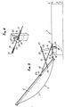
- the equipment of the device is completed according to the invention by means of a tilting lever 16, itself articulated around an axis 17 on the box 2, this axis 17 arranged along the length of the lever so that it it delimits beyond a clean heel 18 coming, at the end of its tilting movement, pressing against a support stop 19, provided on the box and immobilizing the lever in this raised position relative to the plane of the frame 4.
- the lever 16 At its end opposite the heel 18, the lever 16 has a transverse axis 20 which can freely rotate on itself (FIG. 4). On the extension of this axis is fixed a tension spring 21, the opposite end of which is linked to the frame 6 of the panel, rocking around a point of attachment 22. A rod 23 is housed inside spring 21 and arranged to pass freely through a bore 24 provided in an extension 25 of the axis 20. The latter is stopped on the lever 16 by a flange 26.
- the rod 23 finally comprises, beyond the lever 16 relative to the tension spring 21, a stop shoulder 27 for another spring 28, intended to come to work in compression in abutment against the door formed by the extension 25 of the axis 20 when the tilting panel 5 is in the position of maximum opening (opening 140 °), as shown in Figure 3.
- the panel 5 being in the closed position, as illustrated in FIG. 1, with its frame 6 applied to the frame 4 of the box 2, control by the jack 9 the progressive opening of this panel thanks to the relative movement of the rod 11 of the jack with respect to the body 10 and to their respective articulations on the panel 5 and on the box 2 around the axes 12 and 13.
- This opening movement continues gradually and regularly until the panel 5 comes into a first position illustrated in FIG. 2, where the jack 9 is substantially in the extension of the articulated link 14.
- the lever 16 has simultaneously pivoted with the panel 5 until bringing its heel 18 against the stopper 19. In this position, the panel 5 makes an angle with the frame 4 which, in the example considered, is close to 110 °.
- the panel sees its center of gravity move more and more in overhang relative to the hinges 8, driven by its weight it pivots abruptly around its articulation to come at the end of the race in a second position illustrated in Figure 3 with an opening which is here chosen of the order of about 140 °.
- the tension spring 21 is suddenly tensioned and serves to stop the panel, if necessary, in cooperation with a limit stop limit stop (not shown).
- the compression of the spring 28 occurs on the bearing surface 25 of the axis 20 by damping the final stroke of the panel.
- the tension spring 21 previously tensioned facilitating the return of the tilting panel 5 to its intermediate opening position (110 °), before the jack is compressed. and that the panel is returned to the initial closed position where it is applied to the sleeping frame 4.
Claims (3)
Applications Claiming Priority (2)
| Application Number | Priority Date | Filing Date | Title |
|---|---|---|---|
| FR8716586 | 1987-11-30 | ||
| FR8716586A FR2623844B1 (fr) | 1987-11-30 | 1987-11-30 | Exutoire de fumees ou ouverture de toiture analogue a grand debattement du panneau de fermeture |
Publications (2)
| Publication Number | Publication Date |
|---|---|
| EP0319357A1 EP0319357A1 (de) | 1989-06-07 |
| EP0319357B1 true EP0319357B1 (de) | 1992-03-11 |
Family
ID=9357309
Family Applications (1)
| Application Number | Title | Priority Date | Filing Date |
|---|---|---|---|
| EP88402818A Expired - Lifetime EP0319357B1 (de) | 1987-11-30 | 1988-11-09 | Ranchabzugs- oder analoge Dachöffnung mit grossen Öffnungsweg des Schlussdeckels |
Country Status (3)
| Country | Link |
|---|---|
| EP (1) | EP0319357B1 (de) |
| DE (1) | DE3869072D1 (de) |
| FR (1) | FR2623844B1 (de) |
Families Citing this family (3)
| Publication number | Priority date | Publication date | Assignee | Title |
|---|---|---|---|---|
| FR2678307A1 (fr) * | 1991-06-27 | 1992-12-31 | Haras Ind | Dispositif d'amortissement d'ouverture et d'aide a la fermeture d'un exutoire de fumees. |
| CN103437624A (zh) * | 2013-08-22 | 2013-12-11 | 文斌宏 | 沙门自动关门装置 |
| CN115212485B (zh) * | 2022-07-26 | 2023-03-28 | 中南大学 | 一种优化地铁站出入口排烟效果的系统 |
Family Cites Families (4)
| Publication number | Priority date | Publication date | Assignee | Title |
|---|---|---|---|---|
| US2827003A (en) * | 1954-01-20 | 1958-03-18 | Wasco Products | Combination skylight and fire vent construction |
| GB844855A (en) * | 1956-08-23 | 1960-08-17 | Ivor John Thorne | Improvements in counter-balancing means for pivotally mounted ramps, doors, tailboards and the like |
| DE3143318A1 (de) * | 1981-10-31 | 1983-05-19 | Josef 4815 Schloss Holte Fortmeier | "rauch- und waermeabzugsvorrichtung" |
| FR2542360B1 (fr) * | 1983-03-11 | 1987-10-09 | Alcaud Sa | Dispositif de trappe mobile notamment pour le desenfumage |
-
1987
- 1987-11-30 FR FR8716586A patent/FR2623844B1/fr not_active Expired - Fee Related
-
1988
- 1988-11-09 DE DE8888402818T patent/DE3869072D1/de not_active Expired - Fee Related
- 1988-11-09 EP EP88402818A patent/EP0319357B1/de not_active Expired - Lifetime
Also Published As
| Publication number | Publication date |
|---|---|
| FR2623844B1 (fr) | 1990-08-24 |
| DE3869072D1 (de) | 1992-04-16 |
| FR2623844A1 (fr) | 1989-06-02 |
| EP0319357A1 (de) | 1989-06-07 |
Similar Documents
| Publication | Publication Date | Title |
|---|---|---|
| EP0649980B1 (de) | Schubumkehreinrichtung eines Turbinenstrahltriebwerk mit Hilfklappen | |
| EP1644604A2 (de) | Zunge zum verbinden zweier verkleidungen einer flugzeugstruktur | |
| EP0319357B1 (de) | Ranchabzugs- oder analoge Dachöffnung mit grossen Öffnungsweg des Schlussdeckels | |
| FR2758520A1 (fr) | Systeme de porte, en particulier pour un avion version passagers | |
| WO2011077033A2 (fr) | Dispositif d'obturation et ensemble correspondant | |
| EP0972663B1 (de) | Abschlussvorrichtung für Öffnung in einer Fahrzeugkarosserie mit Griff mit geneigter Fläche | |
| FR2907477A1 (fr) | Dispositif de voirie a cadre de support et element de couronnement, tel qu'un tampon ou couvercle ou grille, monte articule a basculement sur le cadre | |
| FR2758522A1 (fr) | Systeme de porte, en particulier pour un avion version passagers | |
| EP0790377B1 (de) | Tür mit einer Sicherheitsvorrichtung | |
| FR2762867A1 (fr) | Dispositif d'articulation d'une coupole sur une costiere d'un lanterneau | |
| FR2661703A1 (fr) | Ensemble exutoire de fumee. | |
| EP0216680B1 (de) | Vorrichtung zum Öffnen und Schliessen von Gebäudeöffnungen mittels Federkraft | |
| FR2696775A1 (fr) | Perfectionnements aux poignées de porte à palettes basculantes. | |
| FR2751370A1 (fr) | Porte anti-pince doigts | |
| EP1134341B1 (de) | Gelenktürsystem für Fahrzeuge, Behälter und dergleichen | |
| FR2882087A1 (fr) | Vehicule possedant un ouvrant dont les mouvements sont securises par un organe a course morte | |
| FR2746842A1 (fr) | Porte a mouvement vertical | |
| BE1003725A3 (fr) | Agencement pour l'ouverture et la fermeture de la porte d'un vehicule mobile, tel qu'un vehicule a passagers. | |
| FR2982897A1 (fr) | Ensemble de retenue pour porte coulissante et installation correspondante | |
| FR2926494A1 (fr) | Vitrage de porte basculant vers le bas | |
| FR2586745A1 (fr) | Dispositif a ressort pneumatique pour l'ouverture et la fermeture des volets de baies de batiments | |
| EP0028973A1 (de) | Vorrichtung zum Bewegen eines Kipptores und so ausgerüstetes Tor | |
| FR2701686A1 (fr) | Ouvrant de véhicule à vitre articulée et dispositif de verrouillage direct de cette vitre. | |
| FR2766513A1 (fr) | Dispositif d'articulation cachee pour chassis a frappe de porte, fenetre ou analogue | |
| EP1188892A1 (de) | Vorrichtung zum Öffnen eines Kraftfahrzeugteils, seiner Verwendung und ein Kraftfahrzeug mit einer solchen Vorrichtung |
Legal Events
| Date | Code | Title | Description |
|---|---|---|---|
| PUAI | Public reference made under article 153(3) epc to a published international application that has entered the european phase |
Free format text: ORIGINAL CODE: 0009012 |
|
| AK | Designated contracting states |
Kind code of ref document: A1 Designated state(s): DE GB IT |
|
| 17P | Request for examination filed |
Effective date: 19900109 |
|
| 17Q | First examination report despatched |
Effective date: 19910327 |
|
| GRAA | (expected) grant |
Free format text: ORIGINAL CODE: 0009210 |
|
| ITF | It: translation for a ep patent filed |
Owner name: BARZANO' E ZANARDO MILANO S.P.A. |
|
| AK | Designated contracting states |
Kind code of ref document: B1 Designated state(s): DE GB IT |
|
| REF | Corresponds to: |
Ref document number: 3869072 Country of ref document: DE Date of ref document: 19920416 |
|
| GBT | Gb: translation of ep patent filed (gb section 77(6)(a)/1977) | ||
| PLBE | No opposition filed within time limit |
Free format text: ORIGINAL CODE: 0009261 |
|
| STAA | Information on the status of an ep patent application or granted ep patent |
Free format text: STATUS: NO OPPOSITION FILED WITHIN TIME LIMIT |
|
| 26N | No opposition filed | ||
| PGFP | Annual fee paid to national office [announced via postgrant information from national office to epo] |
Ref country code: GB Payment date: 19931108 Year of fee payment: 6 |
|
| PGFP | Annual fee paid to national office [announced via postgrant information from national office to epo] |
Ref country code: DE Payment date: 19940531 Year of fee payment: 6 |
|
| PG25 | Lapsed in a contracting state [announced via postgrant information from national office to epo] |
Ref country code: GB Effective date: 19941109 |
|
| GBPC | Gb: european patent ceased through non-payment of renewal fee |
Effective date: 19941109 |
|
| PG25 | Lapsed in a contracting state [announced via postgrant information from national office to epo] |
Ref country code: DE Effective date: 19950801 |
|
| PG25 | Lapsed in a contracting state [announced via postgrant information from national office to epo] |
Ref country code: IT Free format text: LAPSE BECAUSE OF NON-PAYMENT OF DUE FEES Effective date: 20051109 |