EP0318959A2 - Antriebssystem für ene Rotationsdruckpresse - Google Patents
Antriebssystem für ene Rotationsdruckpresse Download PDFInfo
- Publication number
- EP0318959A2 EP0318959A2 EP88119985A EP88119985A EP0318959A2 EP 0318959 A2 EP0318959 A2 EP 0318959A2 EP 88119985 A EP88119985 A EP 88119985A EP 88119985 A EP88119985 A EP 88119985A EP 0318959 A2 EP0318959 A2 EP 0318959A2
- Authority
- EP
- European Patent Office
- Prior art keywords
- main shaft
- plate
- plate drum
- clutch
- rotary press
- Prior art date
- Legal status (The legal status is an assumption and is not a legal conclusion. Google has not performed a legal analysis and makes no representation as to the accuracy of the status listed.)
- Granted
Links
Images


Classifications
-
- B—PERFORMING OPERATIONS; TRANSPORTING
- B41—PRINTING; LINING MACHINES; TYPEWRITERS; STAMPS
- B41F—PRINTING MACHINES OR PRESSES
- B41F13/00—Common details of rotary presses or machines
- B41F13/0008—Driving devices
Definitions
- the present invention relates to a driving system for a rotary press.
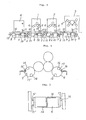
- FIG. 8 The known driving system for a rotary press is illustrated generally in Fig. 8, and a plate clamping device of a plate drum used in the known rotary press is shown in cross-section in Fig. 9.
- reference numerals 01, 02 and 03 respectively designate printing units in the known rotary press
- numeral 04 designates a folding machine in the same.
- a main shaft 05 consists of main shaft sections connected in series along a straight line via a plurality of couplings 06 over the entire length of the rotary press so that it can be rotated synchronously, but for each of the printing units is formed a drive unit 010 which can rotate plate drums 09 and 09′ in each printing unit in a forward or reverse direction at a very slow speed (about 10 rpm) by means of an individual drive motor 08 by disconnecting a clutch 07.
- the respective drive units 010 are encircled by double-dot chain line frames.
- Reference numeral 011 designates branch shafts branched via bevel gear boxes 012, and numeral 013 designates electromagnetic brakes.
- a plate clamping device 014 is provided for the purpose of stretching and securing a plate 015 onto the drum circumference of the plate drum 09, clamping and dismounting of the plate 015 is effected by means of this device and upon performing this operation it is necessary to stop the plate drum 09 at such location that manipulation of the plate clamping device 014 can be effected easily.
- the plate drum is made to rotate in a forward or reverse direction at a very slow speed of about 10 rpm by means of the individual drive motor 08 and when the plate clamping device 014 has come to a position where mounting operation is easy, the plate drums 09 and 09′ are stopped by means of the electromagnetic brake 013 by manipulating a switch button, but in many cases the plate drums would stop at a position considerably deviated from a desired stop position.
- a more specific object of the present invention is to provide a driving system for a rotary press, in which when a plate is to be exchanged on a plate drum, the plate drum can be easily brought to a predetermined stop position for facilitating automation of a plate exchange work.
- Another specific object of the present invention is to provide a driving system for a rotary press, in which a main shaft positioning device can be small-sized, saving of time and labor for exchanging a plate is realized, and hence a working efficiency of a rotary press can be enhanced.
- a driving system for a rotary press including a plurality of printing units, a main shaft for driving all the printing units, a plurality of branch shafts provided as branched from the main shaft and drive units each consisting of a clutch and an individual drive motor and disposed on the main shaft for the respective printing units, in which each of the printing units is provided with an approach switch for detecting a particular position of a plate drum and a plate drum positioning device for correcting the position of the plate drum to the particular position in the proximity of the particular position of the plate drum, and in which each of the drive units is provided with an electromagnetic brake for stopping rotation of the plate drum in response to the approach switch and a main shaft positioning device on the respective sides of the clutch for correcting a phase deviation of a clutch coupling section.
- the above-featured driving system for a rotary press in which there is further provided a fixed position coupling device for connecting the clutch at a particular position on the main shaft.
- the clutch is disconnected and the plate drum is rotated at a very slow speed by means of the individual drive motor.
- the stop position of the plate drum is detected with the aid of the approach switch and rotation of the plate drum is stopped by the electromagnetic brake.
- the stop position is corrected at a high precision by means of the plate drum positioning device.
- a phase deviation at the clutch coupling section is corrected by means of the main shaft positioning device provided at the clutch section.
- the main shaft positioning device is required to correct only the deviation caused by a backlash of the gears between the plate drum and the main shaft, the main shaft positioning device can be small-sized, also shortening of the time necessitated for the plate exchange work becomes possible, and a working efficiency of a rotary press can be increased.
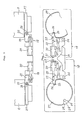
- a main shaft 5 for driving a plurality of printing units 1, 2 and 3 and a folding machine 4 a plurality of branch shafts 11 provided as branched from the main shaft, clutches 7 which are provided on the same main shaft 5 for the respective printing units and which enable disconnection and fixed position coupling, and individual drive motors 8 jointly form drive units 10, 10 and 10 corresponding to the respective printing units.
- the main shaft 5 has a construction consisting of synchronously rotatable main shaft sections connected in series along a straight line via a plurality of shaft couplings 6 over the entire length of the rotary press.
- approach switches 16 for detecting particular positions of the plate drums 9 and 9′, respectively are mounted to a machine frame to perform position detection for detection pieces 17 mounted on one side surfaces of the plate drums 9 and 9′, respectively.
- the detection piece 17 is mounted at such position on the plate drum 9 that it can cooperate with the approach switch 16 to stop the plate drum 9 at a position where the plate clamping device 14 can be easily manipulated.
- electromagnetic brakes 13 for stopping rotation of the main shaft 5 in response to a detection signal issued from the respective approach switches 16 are provided in the respective drive units 10, 10 and 10.
- approach switches 16′ and detection pieces 17′ provided on the other side of the plate drums 9 and 9′ are those for use upon reverse rotation.
- the plate drum 9 is provided with a plate drum positioning device 18 for performing phase matching between the respective units upon clutch coupling. The operation of this device 18 is effected after the plate drum 9 has stopped in the proximity of the particular stop position in response to operation of the approach switch 16 and the electromagnetic brake 13 has been released.
- a terminal end of an air cylinder 20 is coupled via a pin 21 to a member 19 supported from a machine frame, and the other end of the air cylinder is formed as a retractable rod and coupled via a pin 23 to the top end of an arm 22.
- the arm 22 is swingable as pivotably supported from the member 19 via a shaft 24, the outer end of the arm 22 is bifurcated, and a roller 26 is rotatably supported via a pin 25 by the bifurcated end portion.
- the roller 26 is so machined that it can fit at a high precision in a groove 28 formed in a member 27 fixedly secured to the side end of the plate drum 9, and in the proximity of this groove 28 are provided guide slant surface portions 29 for the roller 26 to be used for correcting a deviation of the plate drum stop position.
- main shaft positioning devices 30 which correct a phase deviation at the clutch coupling section caused by a backlash of the gears between the plate drum 9 and the clutch 7 after operation of the plate drum positioning device 18, and thereby coupling at a fixed position of the clutch 7 can be effected.
- the main shaft positioning device 30 transmits the motion of a retractable bottom end rod of an air cylinder 31 as a swinging motion of an outside bifurcated end portion of an arm 32 as shown in Fig. 6, and the bifurcated end portion has a roller 34 rotatably secured thereto via a pin 33.
- the roller 34 is so machined that it can fit at a high precision in a groove 37 of a member 36 which is fixedly secured to the main shaft 5 via a key 35, and this groove 37 is provided with guide slant surface portions 38 for the roller 34.
- a fixed position coupling device 40 for the clutch 7 is composed of an external gear 41 fixedly secured to a shaft end 5a, an external gear 42 fixedly secured to a shaft end 5b, a slide internal gear 43 capable of simultaneously meshing with the gear 41 and the gear 42, a slide ring 45 fitted around the same gear 43 via rolling bearings 44, a swing arm 46, a guide ring plate 47 fixedly secured to a flange portion 41f of the external gear 41 and having a guide hole 47h, and a guide pin 48 studded in the slide internal gear 43, and when the guide hole 47h and the guide pin 48 fit to each other at a high precision and the external gears 41 and 42 are simultaneously meshed with the internal gear 43, or the meshing is released, the function as a clutch is realized.
- the clutch 7 can incorporate the fixed position coupling capability.
- the detection piece 17 mounted to the side surface of the plate drum 9 is detected in position by means of the fixed approach switch 16, and in response to a detection signal issued from the approach switch 16 the electromagnetic brake 13 for the main shaft 5 is actuated to stop and fix the plate drum. Subsequently, since this stop position is subjected to fluctuations over a considerably large range due to variation of a loading condition, at first the electromagnetic brake is released, and positioning of the plate drum is effected by actuating the plate drum positioning device 18.
- the main shaft 5 can be corrected in phase from the drive gears of the plate drum and the like via the branch shaft 11, and hence a phase deviation at the portion of the clutch 7 is reduced to the order of the total amount (about 2 - 3 mm) of the backlashes of the connected gear train. Furthermore, a deviation of phase on this main shaft is corrected by the main shaft positioning device 30. As a result of this correction, a precision in position of the order of ⁇ 0.1 mm can be attained at the clutch gear meshing portion. Under this condition, fixed position coupling of the clutch becomes possible, and clutch connection is effected.
- the driving system for a rotary press can be adapted for automation of a plate exchange work.
- the main shaft positioning device since the main shaft positioning device is required to correct only the deviation caused by a backlash of the gears between the plate drum and the main shaft, the main shaft positioning device can be small-sized, also shortening of the time necessitated for the plate exchange work becomes possible, and a working efficiency of a rotary press can be increased.
Landscapes
- Engineering & Computer Science (AREA)
- Mechanical Engineering (AREA)
- Inking, Control Or Cleaning Of Printing Machines (AREA)
- Rotary Presses (AREA)
Applications Claiming Priority (2)
| Application Number | Priority Date | Filing Date | Title |
|---|---|---|---|
| JP183484/87U | 1987-12-01 | ||
| JP1987183484U JPH0723259Y2 (ja) | 1987-12-01 | 1987-12-01 | 輪転印刷機の駆動装置 |
Publications (3)
| Publication Number | Publication Date |
|---|---|
| EP0318959A2 true EP0318959A2 (de) | 1989-06-07 |
| EP0318959A3 EP0318959A3 (en) | 1990-11-22 |
| EP0318959B1 EP0318959B1 (de) | 1994-07-20 |
Family
ID=16136620
Family Applications (1)
| Application Number | Title | Priority Date | Filing Date |
|---|---|---|---|
| EP88119985A Expired - Lifetime EP0318959B1 (de) | 1987-12-01 | 1988-11-30 | Antriebssystem für ene Rotationsdruckpresse |
Country Status (4)
| Country | Link |
|---|---|
| US (1) | US4899655A (de) |
| EP (1) | EP0318959B1 (de) |
| JP (1) | JPH0723259Y2 (de) |
| DE (1) | DE3850747T2 (de) |
Cited By (2)
| Publication number | Priority date | Publication date | Assignee | Title |
|---|---|---|---|---|
| EP0363803A2 (de) * | 1988-10-13 | 1990-04-18 | Mitsubishi Jukogyo Kabushiki Kaisha | Individuelle Antriebsvorrichtung für Druckeinheiten |
| US5339738A (en) * | 1992-07-09 | 1994-08-23 | Heidelberger Druckmaschinen Ag | Sheet-fed offset printing machine equipped for automated changing of printing plates |
Families Citing this family (6)
| Publication number | Priority date | Publication date | Assignee | Title |
|---|---|---|---|---|
| DE4013462A1 (de) * | 1990-04-27 | 1991-11-07 | Heidelberger Druckmasch Ag | Vorrichtung zum lackieren von bedruckten bogen an druckmaschinen |
| DE4202722B4 (de) * | 1992-01-31 | 2005-09-29 | Heidelberger Druckmaschinen Ag | Sicherheitseinrichtung für Regelungen oder Steuerungen von Antriebseinheiten einer Druckmaschine |
| US5450788A (en) * | 1994-08-05 | 1995-09-19 | Shan; Chen C. | Printer for plastic bags |
| US5816152A (en) * | 1997-09-02 | 1998-10-06 | Delaware Capital Formation, Inc. | Reconfigurable printing press |
| DE102005021217A1 (de) | 2005-05-07 | 2006-11-16 | Koenig & Bauer Ag | Verfahren und zum reproduzierbaren Festlegen der räumlichen Winkellage mindestens eines Zylinders einer Druckmaschine, Vorrichtung zur Durchführung des Verfahrens und eine Druckeinheit |
| CN106042611B (zh) * | 2016-07-14 | 2019-05-28 | 中山松德新材料装备有限公司 | 一种锂电池极片凹版机自动套印系统 |
Citations (4)
| Publication number | Priority date | Publication date | Assignee | Title |
|---|---|---|---|---|
| US1877387A (en) * | 1931-08-08 | 1932-09-13 | Allan J Cline | Driving mechanism for printing presses |
| GB550681A (en) * | 1941-06-07 | 1943-01-19 | Igranic Electric Co Ltd | Improvements in or relating to printing presses comprising a plurality of printing units |
| FR1365695A (fr) * | 1962-08-03 | 1964-07-03 | O M C S A Ohg Cigardi S P A | Dispositif de commande et de synchronisation pour machines à imprimer multiples |
| EP0100778B1 (de) * | 1982-08-10 | 1986-06-11 | Mitsubishi Jukogyo Kabushiki Kaisha | Vorrichtung zum automatischen Auswechseln von Druckplatten |
Family Cites Families (1)
| Publication number | Priority date | Publication date | Assignee | Title |
|---|---|---|---|---|
| US3221651A (en) * | 1962-08-03 | 1965-12-07 | Ohg Cigardi S P A | Multi-units sheet-fed printing machine drive |
-
1987
- 1987-12-01 JP JP1987183484U patent/JPH0723259Y2/ja not_active Expired - Lifetime
-
1988
- 1988-11-30 EP EP88119985A patent/EP0318959B1/de not_active Expired - Lifetime
- 1988-11-30 DE DE3850747T patent/DE3850747T2/de not_active Expired - Fee Related
- 1988-12-01 US US07/278,174 patent/US4899655A/en not_active Expired - Lifetime
Patent Citations (4)
| Publication number | Priority date | Publication date | Assignee | Title |
|---|---|---|---|---|
| US1877387A (en) * | 1931-08-08 | 1932-09-13 | Allan J Cline | Driving mechanism for printing presses |
| GB550681A (en) * | 1941-06-07 | 1943-01-19 | Igranic Electric Co Ltd | Improvements in or relating to printing presses comprising a plurality of printing units |
| FR1365695A (fr) * | 1962-08-03 | 1964-07-03 | O M C S A Ohg Cigardi S P A | Dispositif de commande et de synchronisation pour machines à imprimer multiples |
| EP0100778B1 (de) * | 1982-08-10 | 1986-06-11 | Mitsubishi Jukogyo Kabushiki Kaisha | Vorrichtung zum automatischen Auswechseln von Druckplatten |
Cited By (3)
| Publication number | Priority date | Publication date | Assignee | Title |
|---|---|---|---|---|
| EP0363803A2 (de) * | 1988-10-13 | 1990-04-18 | Mitsubishi Jukogyo Kabushiki Kaisha | Individuelle Antriebsvorrichtung für Druckeinheiten |
| EP0363803B1 (de) * | 1988-10-13 | 1994-08-10 | Mitsubishi Jukogyo Kabushiki Kaisha | Individuelle Antriebsvorrichtung für Druckeinheiten |
| US5339738A (en) * | 1992-07-09 | 1994-08-23 | Heidelberger Druckmaschinen Ag | Sheet-fed offset printing machine equipped for automated changing of printing plates |
Also Published As
| Publication number | Publication date |
|---|---|
| JPH0723259Y2 (ja) | 1995-05-31 |
| US4899655A (en) | 1990-02-13 |
| EP0318959B1 (de) | 1994-07-20 |
| EP0318959A3 (en) | 1990-11-22 |
| DE3850747T2 (de) | 1995-03-16 |
| DE3850747D1 (de) | 1994-08-25 |
| JPH0186532U (de) | 1989-06-08 |
Similar Documents
| Publication | Publication Date | Title |
|---|---|---|
| KR970010907B1 (ko) | 웨이브공급장치의 제어방법 | |
| EP0318959A2 (de) | Antriebssystem für ene Rotationsdruckpresse | |
| CA1081039A (en) | Arrangement for the protection of a perfecting printing press | |
| JPH0796289B2 (ja) | オフセツト輪転印刷機の5胴印刷装置用の調節装置 | |
| EP0268857A2 (de) | Steuerungssystem, um in einer Bogenoffsetdruckmaschine automatisch die Druckplatten zu wechseln | |
| US5184551A (en) | Printing press | |
| US5092242A (en) | Lateral and circumferential register adjustment system for a rotary printing machine | |
| EP0363803B1 (de) | Individuelle Antriebsvorrichtung für Druckeinheiten | |
| JPH0154195B2 (de) | ||
| US5083511A (en) | Apparatus and method for printing plate cylinder--impression cylinder registration | |
| US5241906A (en) | Feeder apparatus for web rotary press | |
| US4499792A (en) | Apparatus for angularly positioning a rotary member | |
| EP0054256A2 (de) | Spindelsperrklinke | |
| US4444106A (en) | Arrangement for selectively connecting coaxial gear wheels of a gear train of a dual mode printing machine | |
| US4362099A (en) | Adjusting device for sheet reversing in a sheet-fed rotary press | |
| US5421257A (en) | Sheet transferring machine for printing machine | |
| US6244406B1 (en) | Drive clutch for a pressure cylinder | |
| EP0655329A1 (de) | Druckschaltvorrichtung für eine Bogendruckmaschine mit einer Wendeeinrichtung | |
| JPS6036946B2 (ja) | 輪転印刷機における主軸の自動連結装置 | |
| US3699886A (en) | Disconnect arrangement for multi-unit printing press | |
| SU1705118A1 (ru) | Устройство дл наложени полосового материала на сборочный барабан | |
| JPS6030830A (ja) | クラツチの位相合せ装置 | |
| US3699887A (en) | Disconnect arrangement for multi-unit printing press | |
| JPH03140245A (ja) | 輪転印刷機の分割版胴 | |
| JPH02169251A (ja) | 枚葉反転印刷機の紙サイズ切換機構 |
Legal Events
| Date | Code | Title | Description |
|---|---|---|---|
| PUAI | Public reference made under article 153(3) epc to a published international application that has entered the european phase |
Free format text: ORIGINAL CODE: 0009012 |
|
| 17P | Request for examination filed |
Effective date: 19881227 |
|
| AK | Designated contracting states |
Kind code of ref document: A2 Designated state(s): DE FR GB |
|
| PUAL | Search report despatched |
Free format text: ORIGINAL CODE: 0009013 |
|
| AK | Designated contracting states |
Kind code of ref document: A3 Designated state(s): DE FR GB |
|
| 17Q | First examination report despatched |
Effective date: 19921106 |
|
| GRAA | (expected) grant |
Free format text: ORIGINAL CODE: 0009210 |
|
| AK | Designated contracting states |
Kind code of ref document: B1 Designated state(s): DE FR GB |
|
| REF | Corresponds to: |
Ref document number: 3850747 Country of ref document: DE Date of ref document: 19940825 |
|
| ET | Fr: translation filed | ||
| PLBI | Opposition filed |
Free format text: ORIGINAL CODE: 0009260 |
|
| 26 | Opposition filed |
Opponent name: ALBERT-FRANKENTHAL AG, FRANKENTHAL C/O KOENIG & BA Effective date: 19950420 |
|
| PLAB | Opposition data, opponent's data or that of the opponent's representative modified |
Free format text: ORIGINAL CODE: 0009299OPPO |
|
| R26 | Opposition filed (corrected) |
Opponent name: KBA KOENIG & BAUER-ALBERT AG WERK WUERZBURG Effective date: 19950420 |
|
| PGFP | Annual fee paid to national office [announced via postgrant information from national office to epo] |
Ref country code: FR Payment date: 19961111 Year of fee payment: 9 |
|
| PGFP | Annual fee paid to national office [announced via postgrant information from national office to epo] |
Ref country code: GB Payment date: 19961121 Year of fee payment: 9 |
|
| PLBO | Opposition rejected |
Free format text: ORIGINAL CODE: EPIDOS REJO |
|
| PG25 | Lapsed in a contracting state [announced via postgrant information from national office to epo] |
Ref country code: GB Free format text: LAPSE BECAUSE OF NON-PAYMENT OF DUE FEES Effective date: 19971130 Ref country code: FR Free format text: THE PATENT HAS BEEN ANNULLED BY A DECISION OF A NATIONAL AUTHORITY Effective date: 19971130 |
|
| PLBN | Opposition rejected |
Free format text: ORIGINAL CODE: 0009273 |
|
| STAA | Information on the status of an ep patent application or granted ep patent |
Free format text: STATUS: OPPOSITION REJECTED |
|
| 27O | Opposition rejected |
Effective date: 19971106 |
|
| GBPC | Gb: european patent ceased through non-payment of renewal fee |
Effective date: 19971130 |
|
| REG | Reference to a national code |
Ref country code: FR Ref legal event code: ST |
|
| PGFP | Annual fee paid to national office [announced via postgrant information from national office to epo] |
Ref country code: DE Payment date: 19981207 Year of fee payment: 11 |
|
| PG25 | Lapsed in a contracting state [announced via postgrant information from national office to epo] |
Ref country code: DE Free format text: LAPSE BECAUSE OF NON-PAYMENT OF DUE FEES Effective date: 20000901 |