EP0318676A2 - Mécanisme enrouler de feuille continue en matière plastique, papier ou semblable - Google Patents
Mécanisme enrouler de feuille continue en matière plastique, papier ou semblable Download PDFInfo
- Publication number
- EP0318676A2 EP0318676A2 EP88116608A EP88116608A EP0318676A2 EP 0318676 A2 EP0318676 A2 EP 0318676A2 EP 88116608 A EP88116608 A EP 88116608A EP 88116608 A EP88116608 A EP 88116608A EP 0318676 A2 EP0318676 A2 EP 0318676A2
- Authority
- EP
- European Patent Office
- Prior art keywords
- web
- winding
- winding tube
- cutting
- beginning
- Prior art date
- Legal status (The legal status is an assumption and is not a legal conclusion. Google has not performed a legal analysis and makes no representation as to the accuracy of the status listed.)
- Withdrawn
Links
Images
Classifications
-
- B—PERFORMING OPERATIONS; TRANSPORTING
- B65—CONVEYING; PACKING; STORING; HANDLING THIN OR FILAMENTARY MATERIAL
- B65H—HANDLING THIN OR FILAMENTARY MATERIAL, e.g. SHEETS, WEBS, CABLES
- B65H19/00—Changing the web roll
- B65H19/22—Changing the web roll in winding mechanisms or in connection with winding operations
- B65H19/26—Cutting-off the web running to the wound web roll
-
- B—PERFORMING OPERATIONS; TRANSPORTING
- B65—CONVEYING; PACKING; STORING; HANDLING THIN OR FILAMENTARY MATERIAL
- B65H—HANDLING THIN OR FILAMENTARY MATERIAL, e.g. SHEETS, WEBS, CABLES
- B65H19/00—Changing the web roll
- B65H19/22—Changing the web roll in winding mechanisms or in connection with winding operations
- B65H19/28—Attaching the leading end of the web to the replacement web-roll core or spindle
-
- B—PERFORMING OPERATIONS; TRANSPORTING
- B65—CONVEYING; PACKING; STORING; HANDLING THIN OR FILAMENTARY MATERIAL
- B65H—HANDLING THIN OR FILAMENTARY MATERIAL, e.g. SHEETS, WEBS, CABLES
- B65H2301/00—Handling processes for sheets or webs
- B65H2301/40—Type of handling process
- B65H2301/41—Winding, unwinding
- B65H2301/414—Winding
- B65H2301/41419—Starting winding process
- B65H2301/41421—Starting winding process involving electrostatic means
-
- B—PERFORMING OPERATIONS; TRANSPORTING
- B65—CONVEYING; PACKING; STORING; HANDLING THIN OR FILAMENTARY MATERIAL
- B65H—HANDLING THIN OR FILAMENTARY MATERIAL, e.g. SHEETS, WEBS, CABLES
- B65H2301/00—Handling processes for sheets or webs
- B65H2301/40—Type of handling process
- B65H2301/41—Winding, unwinding
- B65H2301/417—Handling or changing web rolls
- B65H2301/4187—Relative movement of core or web roll in respect of mandrel
- B65H2301/4189—Cutting
- B65H2301/41894—Cutting knife moving on circular or acuate path, e.g. pivoting around winding roller
Definitions
- the invention relates to a winding device of the type as described in the preamble of the first claim.
- a winding device is known from US Pat. No. 3,476,079, in which after severing the web, the beginning of the web is glued to the empty winding tube with an adhesive applied transversely to the running direction of the web.
- adhesive is applied to the winding tube by means of adhesive rollers and the beginning of the web is attached to the winding tube.
- the start of the web should be taken away from the empty winding tube without slippage, in order to prevent even the slightest lateral run of the web and thus strictly avoid wrinkling.
- the separator for. B. a knife bar arranged across the web and the device for electrostatic charging on a common, across the running web arranged movable carrier, an extremely fast separation process and almost simultaneously a sticking process of the beginning of the web is possible on an empty winding tube.
- the electrostatic charge occurs immediately before the cutting process, which takes only a fraction of a second, with an intensity that suddenly forces the severed web start onto the empty, rotating winding tube, from which the film start is immediately taken without slippage.
- the charging process takes about 2 to 3 seconds.
- the electrostatic charge is only applied to the web for a very short time and with an intensity of approximately 25,000 volts that exceeds the capacity of the static charge on the web.
- both the cutting device and the ionization electrode are arranged next to one another on the carrier and are driven together into the running web, the web is suddenly separated and the beginning of the web is fixed on the empty winding tube, while the end of the web is carried along by the full winding tube and can no longer disturb.
- the alignment of the ionization electrode to the start of the web ensures that the start of the web is applied directly to the empty winding tube.
- the arrangement of the ionizing electrode in the working direction in front of the cutting knives means that the start of the path is intensively loaded and immediately adheres to the winding tube.
- the carrier receiving the cutting device and the ionizing electrode is moved linearly into the web to be separated by means of pneumatic or hydraulic aids.
- a pivoting of the U-shaped carrier, for example, about a pivot point into the running web can be provided if this is more advantageous for spatial reasons.
- the ionizing device can have a length that protrudes beyond the web width or also consist of individual electrode parts in order, for. B. to hold only the lateral and central areas of the separated film on the winding tube.
- a preferred embodiment of the invention is shown in the drawing in a highly schematic manner and explained in more detail below.
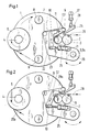
- a fully wound bale 5 is located on the winding tube 4, while the web is deflected around the empty winding tube 3 in this position of the winding device.
- the pivot arm 9 is pivoted about the pivot point 20 into the position shown in FIG. 1 by means of a rotary piston, not shown, when a winding change is to be initiated.
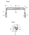
- An approximately U-shaped cutting bar 10 (FIG. 3) with side parts 10a and 10b is arranged on the swivel arm 9 and is designed to be pivotable about the pivot point 22 by means of the pneumatic cylinder 25.
- the cutting bar 10 carries the cutting knife 11 and an electrode body 13.
- electrode tips 14 are arranged, which by means of the connecting line 15 and the connecting cable 17 to one Not shown device for generating an electrical charge are connected.
- the cutting knife 11 (FIG. 4) is fastened on one side of the cutting bar 10 by means of the screws 12.
- the electrode body 13 is fastened by means of the screws 18.
- the cutting bar 10 is used as a common carrier for the cutting or separating device and the device for electrostatically charging the web.
- the cutting bar 10 designed as a carrier can also be linear, i. H.
- they can be moved vertically into the running web by means of pneumatic cylinders in order to sever them and to wind the beginning of the web onto a new winding tube.
- the cutting bar 10 is pivoted about the pivot point 22 into the running web 29 by means of the pneumatic cylinder 25, so that the cutting knife 11 together with the counter-holder 26 cuts the web.
- the winding tube 3 is dragged along by the driven contact roller 2, which has a rubber covering (not shown), so that the cut off web start 29a without any delay is wound on the empty winding tube.
- the web end 29b is wound onto the full winding tube.
- the full sleeve 4 is then removed from the rotating disks 1 arranged on each side of the winding sleeves 3 and 4 and the deflecting rollers 8 and is replaced and replaced by a new, empty winding sleeve.
- the winding tube 3 reaches the position of the tube 4 shown in FIG. 1 with the wound web start.
- the pivot arm 9 with the carrier or the cutting bar 10, 10a and 10b is then pivoted back up into the position shown in FIG. 1 .
- the running web rotates the guide rollers 6 and 7, which are arranged on the swivel arm 9.
Landscapes
- Replacement Of Web Rolls (AREA)
Applications Claiming Priority (2)
| Application Number | Priority Date | Filing Date | Title |
|---|---|---|---|
| DE19873740836 DE3740836C1 (de) | 1987-12-02 | 1987-12-02 | Aufwickelvorrichtung fuer Bahnen aus Kunststoff |
| DE3740836 | 1987-12-02 |
Publications (2)
| Publication Number | Publication Date |
|---|---|
| EP0318676A2 true EP0318676A2 (fr) | 1989-06-07 |
| EP0318676A3 EP0318676A3 (fr) | 1989-08-30 |
Family
ID=6341736
Family Applications (1)
| Application Number | Title | Priority Date | Filing Date |
|---|---|---|---|
| EP88116608A Withdrawn EP0318676A3 (fr) | 1987-12-02 | 1988-10-07 | Mécanisme enrouler de feuille continue en matière plastique, papier ou semblable |
Country Status (2)
| Country | Link |
|---|---|
| EP (1) | EP0318676A3 (fr) |
| DE (1) | DE3740836C1 (fr) |
Cited By (3)
| Publication number | Priority date | Publication date | Assignee | Title |
|---|---|---|---|---|
| CN103754676A (zh) * | 2014-01-25 | 2014-04-30 | 合肥乐凯科技产业有限公司 | 一种聚酯薄膜的制备方法 |
| JP6087418B1 (ja) * | 2015-12-21 | 2017-03-01 | 株式会社不二鉄工所 | シート巻取装置 |
| DE102011088342B4 (de) | 2010-12-15 | 2022-07-07 | Sas Mondon | Kreuzwickelvorrichtung |
Families Citing this family (3)
| Publication number | Priority date | Publication date | Assignee | Title |
|---|---|---|---|---|
| DE59601079D1 (de) * | 1995-03-29 | 1999-02-11 | Heinrich Schnell | Vorrichtung zur aufnahme oder übernahme von stangenlosen wickelkernen |
| DE10203149B4 (de) * | 2001-10-24 | 2005-12-08 | Windmöller & Hölscher Kg | Vorrichtung zum Andrücken eines beweglichen Maschinenteils gegen ein anderes |
| DE10202462B4 (de) * | 2001-10-24 | 2005-11-24 | Windmöller & Hölscher Kg | Vorrichtung zum kontinuierlichen Aufwickeln von Bahnen |
Citations (3)
| Publication number | Priority date | Publication date | Assignee | Title |
|---|---|---|---|---|
| DE2211692A1 (de) * | 1972-03-10 | 1973-09-13 | Paper Converting Machine Co | Bandwickelmaschine |
| DE2823326A1 (de) * | 1977-06-02 | 1978-12-07 | Aldo Bugnone | Endstation einer maschine zur behandlung bandfoermigen materials, beispielsweise einer druckmaschine |
| EP0237903A1 (fr) * | 1986-03-17 | 1987-09-23 | Mitsubishi Jukogyo Kabushiki Kaisha | Appareil de coupure et d'enroulage pour des matériaux en forme de bande comme un film |
Family Cites Families (3)
| Publication number | Priority date | Publication date | Assignee | Title |
|---|---|---|---|---|
| US3476079A (en) * | 1967-12-27 | 1969-11-04 | Procter & Gamble | Apparatus for applying a lateral stripe of adhesive to the tail of a severed web |
| GB1377644A (en) * | 1971-02-05 | 1974-12-18 | Masson Scott Thrissell Eng Ltd | Winding of continuous webs of sheet material |
| DE3535800A1 (de) * | 1985-10-08 | 1987-04-09 | Holtzmann & Cie Ag E | Verfahren und vorrichtung zum aufwickeln einer papierbahn bei der herstellung von in rollenform stapelfaehigem papier |
-
1987
- 1987-12-02 DE DE19873740836 patent/DE3740836C1/de not_active Expired
-
1988
- 1988-10-07 EP EP88116608A patent/EP0318676A3/fr not_active Withdrawn
Patent Citations (3)
| Publication number | Priority date | Publication date | Assignee | Title |
|---|---|---|---|---|
| DE2211692A1 (de) * | 1972-03-10 | 1973-09-13 | Paper Converting Machine Co | Bandwickelmaschine |
| DE2823326A1 (de) * | 1977-06-02 | 1978-12-07 | Aldo Bugnone | Endstation einer maschine zur behandlung bandfoermigen materials, beispielsweise einer druckmaschine |
| EP0237903A1 (fr) * | 1986-03-17 | 1987-09-23 | Mitsubishi Jukogyo Kabushiki Kaisha | Appareil de coupure et d'enroulage pour des matériaux en forme de bande comme un film |
Cited By (4)
| Publication number | Priority date | Publication date | Assignee | Title |
|---|---|---|---|---|
| DE102011088342B4 (de) | 2010-12-15 | 2022-07-07 | Sas Mondon | Kreuzwickelvorrichtung |
| CN103754676A (zh) * | 2014-01-25 | 2014-04-30 | 合肥乐凯科技产业有限公司 | 一种聚酯薄膜的制备方法 |
| CN103754676B (zh) * | 2014-01-25 | 2016-03-30 | 合肥乐凯科技产业有限公司 | 一种聚酯薄膜的制备方法 |
| JP6087418B1 (ja) * | 2015-12-21 | 2017-03-01 | 株式会社不二鉄工所 | シート巻取装置 |
Also Published As
| Publication number | Publication date |
|---|---|
| EP0318676A3 (fr) | 1989-08-30 |
| DE3740836C1 (de) | 1989-06-29 |
Similar Documents
| Publication | Publication Date | Title |
|---|---|---|
| AT399856B (de) | Verfahren und vorrichtung zum automatischen trennen und anwickeln einer warenbahn | |
| EP0458112B1 (fr) | Dispositif pour raccorder des bandes | |
| DE69405957T2 (de) | Verfahren und Vorrichtung zum Aufspulen eines schmalen Bandes | |
| DE2038913C3 (de) | Vorrichtung zum Abschneiden streifenförmiger Abschnitte von einer Reifenverstärkungsbahn und zum Aufbringen der abgeschnittenen Abschnitte auf eine Reifenaufbautrommel | |
| DE3811138A1 (de) | Verfahren und vorrichtung zum behandeln des endabschnitts von aufgerolltem papier | |
| DE3109529A1 (de) | Vorrichtung zum verbinden des hinteren endes einer von einer auslaufenden rolle abgezogenen bahn mit dem vorderen ende einer von einer ersatzrolle abgezogenen bahn | |
| DE2917601A1 (de) | Vorrichtung zum aufwinden von optischen glasfasern o.dgl. | |
| DE4115406A1 (de) | Wickelmaschine zum aufwickeln von materialbahnen | |
| DE4408814A1 (de) | Verfahren und Vorrichtung zum automatischen Verbinden der von Spulen abgewickelten Bahnen | |
| DE3346592A1 (de) | Verfahren zum Ersetzen einer ersten, auslaufenden Wicklung von Streifenmaterial durch eine zweite, neue Wicklung | |
| EP0462157A1 (fr) | Dispositif pour relier des bandes de materiau. | |
| DE4336298A1 (de) | Abwickelvorrichtung mit einer Spliceeinrichtung | |
| EP1172206B1 (fr) | Installation pour introduire des bandes de matériau dans des chemins d'alimentation de machines rotatives d'impression | |
| WO1980001794A1 (fr) | Dispositif permettant d'obtenir un changement de rouleaux volant | |
| EP1163178A1 (fr) | Systeme permettant de relier deux bandes de matiere | |
| DE3151256A1 (de) | Vorrichtung an achslosen wickelmaschinen | |
| EP0395830B1 (fr) | Méthode et dispositif pour enrouler et couper transversalement une bande | |
| EP0318676A2 (fr) | Mécanisme enrouler de feuille continue en matière plastique, papier ou semblable | |
| DE102011088342B4 (de) | Kreuzwickelvorrichtung | |
| DE3816224C1 (fr) | ||
| EP0379861A1 (fr) | Dispositif pour joindre des feuilles | |
| DE3440107C2 (fr) | ||
| DE2417515C2 (de) | Vorrichtung zum Zuführen einer Hüllmaterialbahn zu einem Förderer in einer Zigarettenverpackungsmaschine | |
| EP0627377A1 (fr) | Dispositif pour raccorder des matériaux en bande | |
| EP0395893A1 (fr) | Dispositif pour enrouler ou réenrouler une bande de papier |
Legal Events
| Date | Code | Title | Description |
|---|---|---|---|
| PUAI | Public reference made under article 153(3) epc to a published international application that has entered the european phase |
Free format text: ORIGINAL CODE: 0009012 |
|
| AK | Designated contracting states |
Kind code of ref document: A2 Designated state(s): AT CH DE FR GB IT LI |
|
| PUAL | Search report despatched |
Free format text: ORIGINAL CODE: 0009013 |
|
| STAA | Information on the status of an ep patent application or granted ep patent |
Free format text: STATUS: THE APPLICATION HAS BEEN WITHDRAWN |
|
| AK | Designated contracting states |
Kind code of ref document: A3 Designated state(s): AT CH DE FR GB IT LI |
|
| 18W | Application withdrawn |
Withdrawal date: 19890817 |