EP0318237B1 - Anordnung zum Verpacken - Google Patents
Anordnung zum Verpacken Download PDFInfo
- Publication number
- EP0318237B1 EP0318237B1 EP88311025A EP88311025A EP0318237B1 EP 0318237 B1 EP0318237 B1 EP 0318237B1 EP 88311025 A EP88311025 A EP 88311025A EP 88311025 A EP88311025 A EP 88311025A EP 0318237 B1 EP0318237 B1 EP 0318237B1
- Authority
- EP
- European Patent Office
- Prior art keywords
- sticks
- machine
- shirred
- packaging system
- individual
- Prior art date
- Legal status (The legal status is an assumption and is not a legal conclusion. Google has not performed a legal analysis and makes no representation as to the accuracy of the status listed.)
- Expired - Lifetime
Links
- 238000004806 packaging method and process Methods 0.000 title claims abstract description 21
- 235000013580 sausages Nutrition 0.000 claims abstract description 15
- 239000000463 material Substances 0.000 claims abstract description 14
- 239000011888 foil Substances 0.000 claims abstract description 11
- 239000004033 plastic Substances 0.000 claims abstract description 8
- 229920003023 plastic Polymers 0.000 claims abstract description 8
- 239000002985 plastic film Substances 0.000 claims abstract description 8
- 239000005022 packaging material Substances 0.000 claims description 19
- 230000000717 retained effect Effects 0.000 claims description 10
- 238000000034 method Methods 0.000 claims description 8
- 239000000853 adhesive Substances 0.000 claims description 2
- 230000001070 adhesive effect Effects 0.000 claims description 2
- 238000007789 sealing Methods 0.000 claims description 2
- 238000012856 packing Methods 0.000 claims 1
- 241000237858 Gastropoda Species 0.000 abstract description 16
- PPBRXRYQALVLMV-UHFFFAOYSA-N Styrene Chemical compound C=CC1=CC=CC=C1 PPBRXRYQALVLMV-UHFFFAOYSA-N 0.000 description 2
- 238000005452 bending Methods 0.000 description 2
- 239000004743 Polypropylene Substances 0.000 description 1
- 239000000428 dust Substances 0.000 description 1
- 238000005429 filling process Methods 0.000 description 1
- 238000004519 manufacturing process Methods 0.000 description 1
- 235000013372 meat Nutrition 0.000 description 1
- -1 polypropylene Polymers 0.000 description 1
- 229920001155 polypropylene Polymers 0.000 description 1
- 230000002459 sustained effect Effects 0.000 description 1
Images


Classifications
-
- A—HUMAN NECESSITIES
- A22—BUTCHERING; MEAT TREATMENT; PROCESSING POULTRY OR FISH
- A22C—PROCESSING MEAT, POULTRY, OR FISH
- A22C13/00—Sausage casings
- A22C13/02—Shirring of sausage casings
- A22C13/023—Holders or packs of shirred casings
-
- A—HUMAN NECESSITIES
- A22—BUTCHERING; MEAT TREATMENT; PROCESSING POULTRY OR FISH
- A22C—PROCESSING MEAT, POULTRY, OR FISH
- A22C11/00—Sausage making ; Apparatus for handling or conveying sausage products during manufacture
- A22C11/02—Sausage filling or stuffing machines
- A22C11/0209—Stuffing horn assembly
- A22C11/0218—Stuffing horn assembly with multiple interchangeable stuffing horns, e.g. magazine arrangements
Definitions
- This invention relates to a packaging system for shirred sticks of sausage casing and to a method of transferring such sticks from a shirring machine to a stuffing machine.
- Shirred sticks of sausage casing produced for example by the machine described and illustrated in our European Patent Application No. 0159159 are normally placed in a box manually and then when the box is opened to enable the shirred casings to be stuffed with sausage meat, the sticks are individualy removed, again manually, and applied to the stuffing horn.
- a shirred sausage casing stick packaging system comprising a package in which the sticks are individually supported and separated from each other in such a way that they can readily be released from the packaging and fed to a stuffing machine individually.
- the packaging system takes the form of a magazine with individual compartments for the shirred sticks.
- the packaging comprises a roll of plastic sheet material formed with individual 'U' shaped depressions or troughs adapted to receive the shirred sticks.
- the sheeting With the shirred sticks in place, in the plastic sheeting the sheeting may be rolled up for transport and may then be enclosed in a foil outer casing or bag.
- the sticks are placed in individual compartments in a magazine which can then be mounted on a rotatable arbor and moved round in steps so as to bring the individual compartments into line with the stuffing horn during the stuffing operation.
- the sticks in their troughs or individual compartments may be retained in position by an easily removable adhesive cover sheet.
- the plastic sheet is corrugated and the sticks may be retained on alternate sides of the sheet in adjacent corrugations.
- a honeycombed type structure may be used with the sticks retained in the individual channels in the honeycombe.
- the package of shirred sticks may be retained in a foil or plastics material bag, so that the sticks are kept fresh and humidity is controlled within the bag.
- the foil bag may have an exit in the form of a slot with sealing means running the length of the slot so that the individual shirred sticks may be ejected through the seal when required to be fed to the stuffing machine.
- the slugs may be retained individually between multiple layers or sheets, and the whole assembly formed into a package contained within a foil bag or enclosure.
- the invention relates to a method of transferring shirred sticks of sausage casing from a shirring machine to a stuffing horn without manual handling, thus avoiding damage to the slug.
- the method comprises automatically feeding the shirred sticks from the shirring machine directly into compartments, troughs or similar recesses in a container which retains the sticks in position, separated individually from each other, and then dispensing the sticks automatically one at a time to a stuffing machine.
- a machine for packaging shirred sticks of sausage casing comprising:- a tray along which an elongated length of packaging material may be progressed, the packaging material comprising a series of troughs adapted to receive individual sticks of the sausage casing; means for feeding the sticks, one at a time, into the troughs; and means for indexing the packaging materials so as to move it along, one trough at a time.
- the means for feeding the sticks into the trough may comprise a rotatable cylindrical feeder having one open end into which a stick of casing may be inserted, said feeder also having an open side so that when it is inverted the stick will fall out into a trough.
- the means for indexing the packaging material may comprise a shoe adapted to engage the underside of a trough and means may be provided for moving the shoe both vertically and laterally.
- the machine may also include means for unloading the package of material and for transferring the individual shirred sticks to a stuffing machine.
- said means for unloading the packaging material comprises a device for rotating the package so that its open side is downward so that individual sticks fall out of the package and into a receptacle, said receptacle having means to move it laterally of the package so as to push the released shirred stick onto a projecting part of a stuffing machine.
- Figure 1 a short length of plastic sheet material which may form part of a plastic roll, the sheet material 10 being formed with "U"-shaped depressions 11 having a width of the diameter of the sticks or slugs of shirred sausage casing which are to be transported, and having a length which is the length of the slug.
- the distance between centres of adjacent depressions or troughs may be 1.5 x slug diameter.
- a slug 12 is ejected from a shirring machine 13 automatically into a retaining device 14, to be described in more detail later, which is then rotated to release the slug and allow it to drop into one of the depressions or troughs 11 in the sheet 10.
- the sheet is indexed forward to the next depression to allow the next ejected slug or stick to be inserted into the next depression or trough.
- the sheet may if desired be sealed by a foil layer to control humidity within the package or it may be left open. As illustrated the sheet at this stage is rolled with the open side of the depression facing inwardly. The completed roll may then be bagged in a foil container, and the foil container may have a sealed slot in it through which the slugs may be ejected.
- the completed roll or magazine of slugs is then transported in its sealed foiled container to a stuffing machine.
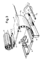
- the roll is then opened up and, if a backing sheet is used as illustrated at 15, the backing sheet 15 is removed and individual slugs retained by guide sheet 15a and then ejected as shown by bending the roll so that its natural bending movement ejects the slug into a receptacle 16 from which it may be automatically transferred to a stuffing horn 17 of a stuffing machine 18, by moving the receptacle in the direction of arrow A in Fig. 3.
- the receptacle 16 is then returned to its original position and the horn 17 rotated by the position 17A ready to fill the stick 12 of shirred casing.
- the roll may be moved in steps by an indexing mechanism, shown generally at 9, which will be described in more detail in relation to Figs. 4 and 7.
- the rolls might for example hold between 50 and 1,000 slugs.
- the large number of slugs would enable a sustained production run to continue with long slugs thus greatly improving efficiency of operations.
- the plastic sheet used may be polypropylene sheet or PVC or styrene. It may for example be of the order of 200 microns thickness.
- a tray along which the packaging material is to be progressed comprises a base plate 111 and two guide flanges 112 and 113 adapted to retain the packaging material on the base plate as it moves along the tray.
- Sticks of shirred material are fed into the troughs of the packaging material by means of a rotatable cylindrical feeder 14, adapted to be rotated through 180° by means of a rack 125 and pinion 126, the rack being moved by a hydraulic cylinder 127.
- the cylinder 14 is open at its end 128 so that sticks of shirred material may be inserted through a bore 129 in a supporting block 130 and into the rotatable cylinder 14.
- the cylinder also has an open side 131 so that when the cylinder is inverted a stick of shirred material will drop out into the adjacent trough 11 of the packaging material 10 (see Fig. 5).
- Figure 5 In Figure 5 is seen empty troughs 11 and filled troughs 11a containing shirred sticks 12.
- the indexing mechanism 9 for moving the packaging material along both in the mechanism of Fig. 2 and that of Fig. 3 is shown below a base plate 111 of the tray.
- the mechanism is supported between end plates 115 and 116.
- Two horizontal support rods 117 and 118 have slidably mounted on them a lateral cross bar 119 which itself supports, via two vertical guide rods 120 and 121, a cross beam 122 at the ends of which are mounted indexing means in the form of shoes 123 and 124.
- shoes 123 and 124 are shaped so as to project through slots 123a and 124a to engage the underside of a trough 11a of the packaging material 10.
- Two hydraulic cylinders 132 and 133 are provided, cylinder 133 being used to move the cross bar 119 and therefore the shoes 123 and 124 from right to left as seen in Figure 5 and cylinder 132 being arranged to raise and lower the crossbeam 122 together with the shoes 123 and 124.
- the mechanism works by first raising the shoes 123 and 124 so that they engage one of the troughs 11a of the packaging material and then operating the cylinder 133 so as to move the troughs along from right to left in Figure 5 thus indexing the packaging material along so that the next trough 11 is located in the proper position to receive a shirred stick 12.
- the shoes are then lowered and returned to their original position while operating the hydraulic cylinders in the reverse order.
- indexing mechanism 9 shown in detail in Figures 4 to 7 is shown in Figure 2 with the feeding mechanism 14 in its operative position. However, the same indexing mechanism 9 is shown in Figure 3 inverted and without the feeding mechanism 14 where the unit is adapted for use when transferring the shirred sticks to a stuffing machine.
- the slugs do not get damaged during handling, and need not be touched by human hand at any stage.
- the fact that the slugs are kept at constant humidity even in very dry or very humid conditions, and the fact that the slugs are kept free from dust etc. are additional advantages.
Landscapes
- Engineering & Computer Science (AREA)
- Life Sciences & Earth Sciences (AREA)
- Wood Science & Technology (AREA)
- Zoology (AREA)
- Food Science & Technology (AREA)
- Auxiliary Devices For And Details Of Packaging Control (AREA)
- Container Filling Or Packaging Operations (AREA)
- Wrapping Of Specific Fragile Articles (AREA)
- Control And Other Processes For Unpacking Of Materials (AREA)
- Containers And Plastic Fillers For Packaging (AREA)
- Supplying Of Containers To The Packaging Station (AREA)
- Packages (AREA)
- Dental Preparations (AREA)
- Treating Waste Gases (AREA)
- Transition And Organic Metals Composition Catalysts For Addition Polymerization (AREA)
Claims (16)
- Verpackungssystem für geraffte Wursthüllenstäbe, mit einer Packung, in welcher die Stäbe einzeln abgestützt und voneinander derart getrennt sind, daß sie aus der Packung leicht freigegeben und einzeln einer Stopfmaschine zugeführt werden können.
- Verpackungssystem nach Anspruch 1 in Form eines Magazins mit einzelnen Abteilen für die gerafften Stäbe.
- Verpackungssystem nach Anspruch 1 oder Anspruch 2 mit einer Rolle aus Kunststoffolienmaterial, das mit einzelnen U-förmigen Vertiefungen oder Trögen geformt ist, die befähigt sind, die gerafften Stäbe aufzunehmen.
- Verpackungssystem nach Anspruch 1, mit einem Magazin, das einzelne Abteile zur Aufnahme der Stäbe aufweist, wobei das Magazin so ausgebildet ist, daß es auf einer drehbaren Welle montierbar und in Schritten herumbewegbar ist, um die einzelnen Abteile während des Stopfvorganges mit einem Stopfhorn auszurichten.
- Verpackungssystem nach einem der Ansprüche 1 bis 4, bei welchem die Stäbe in ihren Trögen oder einzelnen Abteilen durch eine leicht entfernbare klebende Abdeckfolie in Position gehalten sind.
- Verpackungssystem nach Anspruch 5, rückbezogen auf Anspruch 3, bei welchem die Kunststoffolie gewellt ist und die Stäbe auf abwechselnden Seiten der Folie in benachbarten Wellungen gehalten sind.
- Verpackungssystem nach Anspruch 1 mit einer bienenwabenartigen Struktur, wobei die Stäbe in den einzelnen Kanälen der Bienenwabe gehalten sind.
- Verpackungssystem nach einem der vorhergehenden Ansprüche, mit Mitteln zum Abgeben jeweils eines der Stäbe an die Stopfmaschine.
- Verpackungssystem nach einem der vorhergehenden Ansprüche, bei welchem die Packung von gerafften Stäben in einem Foliensack oder einem Kunststoffmaterialsack gehalten ist, so daß die Stäbe frisch gehalten sind und die Feuchtigkeit innerhalb des Sackes kontrolliert ist.
- Verpackungssystem nach Anspruch 8, bei welchem der Sack einen Ausgang in Form eines Schlitzes mit Abdichtungsmitteln aufweist, die entlang des Schlitzes verlaufen, so daß die einzelnen gerafften Stäbe durch die Dichtung hindurch ausgestoßen werden können, wenn es erforderlich ist, sie der Stopfmaschine zuzuführen.
- Verfahren zum Überführen geraffter Stäbe einer Wursthülle aus einer Raffmaschine zu einem Stopfhorn ohne manuelle Handhabung, wobei auf diese Weise eine Beschädigung des Rohlings vermieden wird, wobei das Verfahren das automatische Zuführen der gerafften Stäbe von der Raffmaschine direkt in Abteile, Tröge oder ähnliche Ausnehmungen in einem Behälter umfaßt, welcher die einzeln voneinander getrennten Stäbe in Position hält, und sodann das automatische Abgeben jeweils eines der Stäbe an eine Stopfmaschine.
- Maschine zum Verpacken geraffter Stäbe einer Wursthülle, wobei die Maschine umfaßt:
eine Rinne, entlang welcher eine langgestreckte Bahn Verpackungsmaterial vorgeschoben werden kann, wobei das Verpackungsmaterial eine Reihe von Trögen aufweist, die befähigt sind, einzelne Stäbe der Wursthülle aufzunehmen,
Mittel zum Zuführen jeweils eines der Stäbe in die Tröge; und
Mitteln zum lndexieren des Verpackungsmaterials, um dieses jeweils um einen Trog weiterzubewegen. - Maschine nach Anspruch 12, bei welcher die Mittel zum Zuführen der Stäbe zu den Trögen einen rotierenden zylindrischen Zuführer aufweisen, der ein offenes Ende hat, in welches ein Hüllenstab eingeführt werden kann, wobei der Zuführer auch eine offene Seite hat, so daß beim Umdrehen des Zuführers der Stab heraus in einen Trog fällt.
- Maschine nach Anspruch 12 oder 13, bei welcher die Mittel zum Indexieren des Verpackungsmaterials einen Schuh aufweisen, der befähigt ist, an der Unterseite eines Troges anzugreifen, und Mittel vorgesehen sind, um den Schuh sowohl vertikal als auch seitwärts zu bewegen.
- Maschine nach Anspruch 12, 13 oder 14, mit Mitteln zum Entladen der Packung von Material und zum Überführen der einzelnen gerafften Stäbe zu einer Stopfmaschine.
- Maschine nach Anspruch 15, bei welcher die Mittel zum Entladen der Packung von Material eine Vorrichtung zum Drehen der Packung aufweisen, so daß ihre offene Seite nach unten gerichtet ist, damit die einzelnen Stäbe aus der Packung und in eine Aufnahme fallen, wobei die Aufnahme Mittel aufweist, um sie bezüglich der Verpackung seitwärts zu bewegen, um die freigegebenen gerafften Stäbe in einen vorspringenden Teil einer Stopfmaschine zu schieben.
Priority Applications (1)
| Application Number | Priority Date | Filing Date | Title |
|---|---|---|---|
| AT88311025T ATE77206T1 (de) | 1987-11-27 | 1988-11-22 | Anordnung zum verpacken. |
Applications Claiming Priority (2)
| Application Number | Priority Date | Filing Date | Title |
|---|---|---|---|
| GB878727808A GB8727808D0 (en) | 1987-11-27 | 1987-11-27 | Packaging system |
| GB8727808 | 1987-11-27 |
Publications (2)
| Publication Number | Publication Date |
|---|---|
| EP0318237A1 EP0318237A1 (de) | 1989-05-31 |
| EP0318237B1 true EP0318237B1 (de) | 1992-06-17 |
Family
ID=10627635
Family Applications (1)
| Application Number | Title | Priority Date | Filing Date |
|---|---|---|---|
| EP88311025A Expired - Lifetime EP0318237B1 (de) | 1987-11-27 | 1988-11-22 | Anordnung zum Verpacken |
Country Status (13)
| Country | Link |
|---|---|
| EP (1) | EP0318237B1 (de) |
| JP (1) | JPH01240406A (de) |
| AT (1) | ATE77206T1 (de) |
| AU (2) | AU2575888A (de) |
| DE (1) | DE3872180T2 (de) |
| DK (1) | DK642688A (de) |
| ES (1) | ES2034263T3 (de) |
| FI (1) | FI885304A7 (de) |
| GB (1) | GB8727808D0 (de) |
| GR (1) | GR3004952T3 (de) |
| NO (1) | NO885237L (de) |
| NZ (1) | NZ227026A (de) |
| ZA (1) | ZA888710B (de) |
Families Citing this family (5)
| Publication number | Priority date | Publication date | Assignee | Title |
|---|---|---|---|---|
| DE4223128C2 (de) * | 1991-07-15 | 1995-06-14 | Handtmann Albert Maschf | Verfahren und Vorrichtung zum Vereinzeln und Aufbringen einer Darmraupe auf ein Füllrohr |
| DE10001708C2 (de) * | 2000-01-18 | 2003-03-27 | Tipro Trading Exp Imp Gmbh | Einrichtung zum Vorstapeln von Naturdärmen |
| US7476147B2 (en) | 2004-05-03 | 2009-01-13 | Viskoteepak Belgium Nv | Belt fed food casing system |
| US20050245185A1 (en) * | 2004-05-03 | 2005-11-03 | Rossi Scott J | Belt fed food casing system |
| AT523363B1 (de) * | 2019-12-20 | 2021-11-15 | Khu Peter | Haltesystem für Stückgüter |
Family Cites Families (10)
| Publication number | Priority date | Publication date | Assignee | Title |
|---|---|---|---|---|
| US3150410A (en) * | 1962-01-05 | 1964-09-29 | Tee Pak Inc | Sausage stuffing machine |
| BE648381A (de) * | 1963-05-29 | 1964-11-25 | ||
| FR1395140A (fr) * | 1964-04-15 | 1965-04-09 | Townsend Engineering Co | Machine à remplir des boyaux de chair à saucisse et produits analogues |
| FR1577771A (de) * | 1968-08-26 | 1969-08-08 | ||
| US3672001A (en) * | 1970-06-29 | 1972-06-27 | Townsend Engineering Co | Product encasing machine |
| US3673760A (en) * | 1970-10-26 | 1972-07-04 | American Can Co | Packaging method and apparatus |
| DE2910476A1 (de) * | 1979-03-16 | 1980-09-25 | Niedecker Herbert | Verfahren und vorrichtung zum vorbereitenden behandeln von gerafften kunstdarmhuellen |
| DE3019981A1 (de) * | 1980-05-24 | 1981-12-03 | Albert Handtmann Gmbh & Co, 7950 Biberach | Magazinvorichtung fuer wursthuellen an einer wurstfuellmaschine |
| DE3248338A1 (de) * | 1982-12-28 | 1984-06-28 | Wolff Walsrode Ag, 3030 Walsrode | Verfahren zum verpacken von schlauchfoermigen gerafften nahrungsmittelhuellen |
| FI841291A7 (fi) * | 1983-03-31 | 1984-10-01 | Union Carbide Corp | Paofyllningsfoerfarande och -anordning samt hoeljesprodukt att anvaendas i anordningen. |
-
1987
- 1987-11-27 GB GB878727808A patent/GB8727808D0/en active Pending
-
1988
- 1988-11-16 FI FI885304A patent/FI885304A7/fi not_active IP Right Cessation
- 1988-11-17 DK DK642688A patent/DK642688A/da not_active Application Discontinuation
- 1988-11-21 ZA ZA888710A patent/ZA888710B/xx unknown
- 1988-11-21 NZ NZ227026A patent/NZ227026A/en unknown
- 1988-11-21 AU AU25758/88A patent/AU2575888A/en not_active Abandoned
- 1988-11-22 ES ES198888311025T patent/ES2034263T3/es not_active Expired - Lifetime
- 1988-11-22 DE DE8888311025T patent/DE3872180T2/de not_active Expired - Lifetime
- 1988-11-22 AT AT88311025T patent/ATE77206T1/de not_active IP Right Cessation
- 1988-11-22 EP EP88311025A patent/EP0318237B1/de not_active Expired - Lifetime
- 1988-11-24 NO NO88885237A patent/NO885237L/no unknown
- 1988-11-25 JP JP63296410A patent/JPH01240406A/ja active Pending
-
1992
- 1992-06-12 AU AU18219/92A patent/AU1821992A/en not_active Abandoned
- 1992-06-18 GR GR920401149T patent/GR3004952T3/el unknown
Also Published As
| Publication number | Publication date |
|---|---|
| NO885237D0 (no) | 1988-11-24 |
| DK642688D0 (da) | 1988-11-17 |
| AU1821992A (en) | 1992-08-13 |
| ZA888710B (en) | 1989-08-30 |
| EP0318237A1 (de) | 1989-05-31 |
| AU2575888A (en) | 1989-06-01 |
| ATE77206T1 (de) | 1992-07-15 |
| FI885304A0 (fi) | 1988-11-16 |
| DE3872180T2 (de) | 1992-12-03 |
| JPH01240406A (ja) | 1989-09-26 |
| GR3004952T3 (de) | 1993-04-28 |
| ES2034263T3 (es) | 1993-04-01 |
| DK642688A (da) | 1989-05-28 |
| FI885304A7 (fi) | 1989-05-28 |
| DE3872180D1 (de) | 1992-07-23 |
| NZ227026A (en) | 1990-07-26 |
| GB8727808D0 (en) | 1987-12-31 |
| NO885237L (no) | 1989-05-29 |
Similar Documents
| Publication | Publication Date | Title |
|---|---|---|
| US4466229A (en) | Process and machine for automatically packing individual drinking straws, or similarly shaped articles, in weldable films | |
| US4771882A (en) | Cigarette package with spacer | |
| CA2283443C (en) | Method and apparatus for transferring objects | |
| US4546901A (en) | Apparatus for dispensing medication | |
| US4633652A (en) | Method and apparatus for automatically packing sausage links | |
| US3545164A (en) | Apparatus and method for filling packaging receptacles | |
| US4041677A (en) | Packaging apparatus | |
| US3534522A (en) | Method and apparatus for transporting and filling containers with cigarettes or the like | |
| US4240854A (en) | Fan-folded labeling technique | |
| KR101745591B1 (ko) | 진단키트용 포장시스템 | |
| EP0208029B1 (de) | Abgabevorrichtung für Medikamente | |
| US3651614A (en) | Packaging of bottles, jars and other articles | |
| EP0318237B1 (de) | Anordnung zum Verpacken | |
| US4570418A (en) | Device for the automatic boxing of bags or sachets into containers | |
| CN118701385A (zh) | 用于形成包装的叠堆的方法和装置 | |
| US3331183A (en) | Sealing packages | |
| US5476354A (en) | Method and apparatus for opening soft-cup cigarette packs | |
| EP0230795A2 (de) | Verfahren und Apparat zum automatischen Verpacken von Würstchen | |
| JPS61259934A (ja) | ラベルマガジンアセンブリおよび供給マガジン交換方法 | |
| WO1984001762A1 (en) | A method and a machine for packing sliced products in a container to be vacuum sealed | |
| ITBO20060682A1 (it) | Apparecchiatura per il confezionamento di un prodotto. | |
| KR101480941B1 (ko) | 견과류 포장장치 | |
| JP3000407B2 (ja) | 紙管供給装置 | |
| JP2506547B2 (ja) | 豆腐のパック詰め装置 | |
| US3678647A (en) | Packaging of bottles or other articles |
Legal Events
| Date | Code | Title | Description |
|---|---|---|---|
| PUAI | Public reference made under article 153(3) epc to a published international application that has entered the european phase |
Free format text: ORIGINAL CODE: 0009012 |
|
| AK | Designated contracting states |
Kind code of ref document: A1 Designated state(s): AT BE CH DE ES FR GB GR IT LI LU NL SE |
|
| 17P | Request for examination filed |
Effective date: 19891113 |
|
| 17Q | First examination report despatched |
Effective date: 19910108 |
|
| ITF | It: translation for a ep patent filed | ||
| GRAA | (expected) grant |
Free format text: ORIGINAL CODE: 0009210 |
|
| AK | Designated contracting states |
Kind code of ref document: B1 Designated state(s): AT BE CH DE ES FR GB GR IT LI LU NL SE |
|
| REF | Corresponds to: |
Ref document number: 77206 Country of ref document: AT Date of ref document: 19920715 Kind code of ref document: T |
|
| REF | Corresponds to: |
Ref document number: 3872180 Country of ref document: DE Date of ref document: 19920723 |
|
| ET | Fr: translation filed | ||
| PGFP | Annual fee paid to national office [announced via postgrant information from national office to epo] |
Ref country code: GB Payment date: 19921110 Year of fee payment: 5 |
|
| PGFP | Annual fee paid to national office [announced via postgrant information from national office to epo] |
Ref country code: AT Payment date: 19921112 Year of fee payment: 5 |
|
| PGFP | Annual fee paid to national office [announced via postgrant information from national office to epo] |
Ref country code: SE Payment date: 19921116 Year of fee payment: 5 |
|
| PGFP | Annual fee paid to national office [announced via postgrant information from national office to epo] |
Ref country code: FR Payment date: 19921124 Year of fee payment: 5 |
|
| PGFP | Annual fee paid to national office [announced via postgrant information from national office to epo] |
Ref country code: CH Payment date: 19921125 Year of fee payment: 5 |
|
| PGFP | Annual fee paid to national office [announced via postgrant information from national office to epo] |
Ref country code: NL Payment date: 19921130 Year of fee payment: 5 Ref country code: GR Payment date: 19921130 Year of fee payment: 5 Ref country code: ES Payment date: 19921130 Year of fee payment: 5 |
|
| PGFP | Annual fee paid to national office [announced via postgrant information from national office to epo] |
Ref country code: LU Payment date: 19921210 Year of fee payment: 5 |
|
| PGFP | Annual fee paid to national office [announced via postgrant information from national office to epo] |
Ref country code: DE Payment date: 19921212 Year of fee payment: 5 |
|
| PGFP | Annual fee paid to national office [announced via postgrant information from national office to epo] |
Ref country code: BE Payment date: 19921223 Year of fee payment: 5 |
|
| REG | Reference to a national code |
Ref country code: GR Ref legal event code: FG4A Free format text: 3004952 |
|
| EPTA | Lu: last paid annual fee | ||
| REG | Reference to a national code |
Ref country code: ES Ref legal event code: FG2A Ref document number: 2034263 Country of ref document: ES Kind code of ref document: T3 |
|
| PLBE | No opposition filed within time limit |
Free format text: ORIGINAL CODE: 0009261 |
|
| STAA | Information on the status of an ep patent application or granted ep patent |
Free format text: STATUS: NO OPPOSITION FILED WITHIN TIME LIMIT |
|
| 26N | No opposition filed | ||
| PG25 | Lapsed in a contracting state [announced via postgrant information from national office to epo] |
Ref country code: LU Free format text: LAPSE BECAUSE OF NON-PAYMENT OF DUE FEES Effective date: 19931122 Ref country code: GB Effective date: 19931122 Ref country code: AT Effective date: 19931122 |
|
| PG25 | Lapsed in a contracting state [announced via postgrant information from national office to epo] |
Ref country code: SE Effective date: 19931123 Ref country code: ES Free format text: LAPSE BECAUSE OF NON-PAYMENT OF DUE FEES Effective date: 19931123 |
|
| PG25 | Lapsed in a contracting state [announced via postgrant information from national office to epo] |
Ref country code: LI Effective date: 19931130 Ref country code: CH Effective date: 19931130 Ref country code: BE Effective date: 19931130 |
|
| BERE | Be: lapsed |
Owner name: DEVRO INC. Effective date: 19931130 |
|
| PG25 | Lapsed in a contracting state [announced via postgrant information from national office to epo] |
Ref country code: GR Free format text: THE PATENT HAS BEEN ANNULLED BY A DECISION OF A NATIONAL AUTHORITY Effective date: 19940531 |
|
| PG25 | Lapsed in a contracting state [announced via postgrant information from national office to epo] |
Ref country code: NL Effective date: 19940601 |
|
| NLV4 | Nl: lapsed or anulled due to non-payment of the annual fee | ||
| GBPC | Gb: european patent ceased through non-payment of renewal fee |
Effective date: 19931122 |
|
| PG25 | Lapsed in a contracting state [announced via postgrant information from national office to epo] |
Ref country code: FR Effective date: 19940729 |
|
| REG | Reference to a national code |
Ref country code: CH Ref legal event code: PL |
|
| PG25 | Lapsed in a contracting state [announced via postgrant information from national office to epo] |
Ref country code: DE Effective date: 19940802 |
|
| REG | Reference to a national code |
Ref country code: FR Ref legal event code: ST |
|
| REG | Reference to a national code |
Ref country code: GR Ref legal event code: MM2A Free format text: 3004952 |
|
| EUG | Se: european patent has lapsed |
Ref document number: 88311025.6 Effective date: 19940610 |
|
| REG | Reference to a national code |
Ref country code: ES Ref legal event code: FD2A Effective date: 19941214 |
|
| PG25 | Lapsed in a contracting state [announced via postgrant information from national office to epo] |
Ref country code: IT Free format text: LAPSE BECAUSE OF NON-PAYMENT OF DUE FEES Effective date: 20051122 |