EP0315347B1 - Elektrisch gesteuerter und hydraulisch betätigter X-Y-Schaltmechanismus - Google Patents
Elektrisch gesteuerter und hydraulisch betätigter X-Y-Schaltmechanismus Download PDFInfo
- Publication number
- EP0315347B1 EP0315347B1 EP88309969A EP88309969A EP0315347B1 EP 0315347 B1 EP0315347 B1 EP 0315347B1 EP 88309969 A EP88309969 A EP 88309969A EP 88309969 A EP88309969 A EP 88309969A EP 0315347 B1 EP0315347 B1 EP 0315347B1
- Authority
- EP
- European Patent Office
- Prior art keywords
- shift
- shaft
- housing
- valves
- pressurized fluid
- Prior art date
- Legal status (The legal status is an assumption and is not a legal conclusion. Google has not performed a legal analysis and makes no representation as to the accuracy of the status listed.)
- Expired - Lifetime
Links
- 230000007246 mechanism Effects 0.000 title claims description 47
- 239000012530 fluid Substances 0.000 title claims description 28
- 230000005540 biological transmission Effects 0.000 claims description 16
- 230000008859 change Effects 0.000 claims description 6
- 230000000903 blocking effect Effects 0.000 claims 2
- 230000007935 neutral effect Effects 0.000 description 12
- 230000009347 mechanical transmission Effects 0.000 description 10
- 230000000712 assembly Effects 0.000 description 6
- 238000000429 assembly Methods 0.000 description 6
- 238000006073 displacement reaction Methods 0.000 description 6
- 230000004048 modification Effects 0.000 description 2
- 238000012986 modification Methods 0.000 description 2
- 230000009471 action Effects 0.000 description 1
- 230000001276 controlling effect Effects 0.000 description 1
- 230000000694 effects Effects 0.000 description 1
- 230000008676 import Effects 0.000 description 1
- 230000003993 interaction Effects 0.000 description 1
- 238000004519 manufacturing process Methods 0.000 description 1
- 230000001105 regulatory effect Effects 0.000 description 1
- 230000008439 repair process Effects 0.000 description 1
- 230000000717 retained effect Effects 0.000 description 1
Images

Classifications
-
- F—MECHANICAL ENGINEERING; LIGHTING; HEATING; WEAPONS; BLASTING
- F16—ENGINEERING ELEMENTS AND UNITS; GENERAL MEASURES FOR PRODUCING AND MAINTAINING EFFECTIVE FUNCTIONING OF MACHINES OR INSTALLATIONS; THERMAL INSULATION IN GENERAL
- F16H—GEARING
- F16H61/00—Control functions within control units of change-speed- or reversing-gearings for conveying rotary motion ; Control of exclusively fluid gearing, friction gearing, gearings with endless flexible members or other particular types of gearing
- F16H61/26—Generation or transmission of movements for final actuating mechanisms
- F16H61/28—Generation or transmission of movements for final actuating mechanisms with at least one movement of the final actuating mechanism being caused by a non-mechanical force, e.g. power-assisted
- F16H61/2807—Generation or transmission of movements for final actuating mechanisms with at least one movement of the final actuating mechanism being caused by a non-mechanical force, e.g. power-assisted using electric control signals for shift actuators, e.g. electro-hydraulic control therefor
-
- F—MECHANICAL ENGINEERING; LIGHTING; HEATING; WEAPONS; BLASTING
- F16—ENGINEERING ELEMENTS AND UNITS; GENERAL MEASURES FOR PRODUCING AND MAINTAINING EFFECTIVE FUNCTIONING OF MACHINES OR INSTALLATIONS; THERMAL INSULATION IN GENERAL
- F16H—GEARING
- F16H61/00—Control functions within control units of change-speed- or reversing-gearings for conveying rotary motion ; Control of exclusively fluid gearing, friction gearing, gearings with endless flexible members or other particular types of gearing
- F16H61/26—Generation or transmission of movements for final actuating mechanisms
- F16H61/28—Generation or transmission of movements for final actuating mechanisms with at least one movement of the final actuating mechanism being caused by a non-mechanical force, e.g. power-assisted
- F16H61/30—Hydraulic or pneumatic motors or related fluid control means therefor
- F16H2061/307—Actuators with three or more defined positions, e.g. three position servos
-
- F—MECHANICAL ENGINEERING; LIGHTING; HEATING; WEAPONS; BLASTING
- F16—ENGINEERING ELEMENTS AND UNITS; GENERAL MEASURES FOR PRODUCING AND MAINTAINING EFFECTIVE FUNCTIONING OF MACHINES OR INSTALLATIONS; THERMAL INSULATION IN GENERAL
- F16H—GEARING
- F16H61/00—Control functions within control units of change-speed- or reversing-gearings for conveying rotary motion ; Control of exclusively fluid gearing, friction gearing, gearings with endless flexible members or other particular types of gearing
- F16H61/26—Generation or transmission of movements for final actuating mechanisms
- F16H61/28—Generation or transmission of movements for final actuating mechanisms with at least one movement of the final actuating mechanism being caused by a non-mechanical force, e.g. power-assisted
- F16H61/30—Hydraulic or pneumatic motors or related fluid control means therefor
- F16H2061/308—Modular hydraulic shift units, i.e. preassembled actuator units for select and shift movements adapted for being mounted on transmission casing
-
- Y—GENERAL TAGGING OF NEW TECHNOLOGICAL DEVELOPMENTS; GENERAL TAGGING OF CROSS-SECTIONAL TECHNOLOGIES SPANNING OVER SEVERAL SECTIONS OF THE IPC; TECHNICAL SUBJECTS COVERED BY FORMER USPC CROSS-REFERENCE ART COLLECTIONS [XRACs] AND DIGESTS
- Y10—TECHNICAL SUBJECTS COVERED BY FORMER USPC
- Y10T—TECHNICAL SUBJECTS COVERED BY FORMER US CLASSIFICATION
- Y10T74/00—Machine element or mechanism
- Y10T74/19—Gearing
- Y10T74/19219—Interchangeably locked
- Y10T74/19251—Control mechanism
-
- Y—GENERAL TAGGING OF NEW TECHNOLOGICAL DEVELOPMENTS; GENERAL TAGGING OF CROSS-SECTIONAL TECHNOLOGIES SPANNING OVER SEVERAL SECTIONS OF THE IPC; TECHNICAL SUBJECTS COVERED BY FORMER USPC CROSS-REFERENCE ART COLLECTIONS [XRACs] AND DIGESTS
- Y10—TECHNICAL SUBJECTS COVERED BY FORMER USPC
- Y10T—TECHNICAL SUBJECTS COVERED BY FORMER US CLASSIFICATION
- Y10T74/00—Machine element or mechanism
- Y10T74/19—Gearing
- Y10T74/19219—Interchangeably locked
- Y10T74/19377—Slidable keys or clutches
- Y10T74/19414—Single clutch shaft
- Y10T74/19419—Progressive
- Y10T74/19423—Multiple key
- Y10T74/19428—Spur
- Y10T74/19433—Fluid operated
-
- Y—GENERAL TAGGING OF NEW TECHNOLOGICAL DEVELOPMENTS; GENERAL TAGGING OF CROSS-SECTIONAL TECHNOLOGIES SPANNING OVER SEVERAL SECTIONS OF THE IPC; TECHNICAL SUBJECTS COVERED BY FORMER USPC CROSS-REFERENCE ART COLLECTIONS [XRACs] AND DIGESTS
- Y10—TECHNICAL SUBJECTS COVERED BY FORMER USPC
- Y10T—TECHNICAL SUBJECTS COVERED BY FORMER US CLASSIFICATION
- Y10T74/00—Machine element or mechanism
- Y10T74/19—Gearing
- Y10T74/19219—Interchangeably locked
- Y10T74/19377—Slidable keys or clutches
- Y10T74/19414—Single clutch shaft
- Y10T74/19419—Progressive
- Y10T74/19423—Multiple key
- Y10T74/19428—Spur
- Y10T74/19437—Electrically operated
-
- Y—GENERAL TAGGING OF NEW TECHNOLOGICAL DEVELOPMENTS; GENERAL TAGGING OF CROSS-SECTIONAL TECHNOLOGIES SPANNING OVER SEVERAL SECTIONS OF THE IPC; TECHNICAL SUBJECTS COVERED BY FORMER USPC CROSS-REFERENCE ART COLLECTIONS [XRACs] AND DIGESTS
- Y10—TECHNICAL SUBJECTS COVERED BY FORMER USPC
- Y10T—TECHNICAL SUBJECTS COVERED BY FORMER US CLASSIFICATION
- Y10T74/00—Machine element or mechanism
- Y10T74/20—Control lever and linkage systems
- Y10T74/20012—Multiple controlled elements
- Y10T74/20018—Transmission control
- Y10T74/20024—Fluid actuator
-
- Y—GENERAL TAGGING OF NEW TECHNOLOGICAL DEVELOPMENTS; GENERAL TAGGING OF CROSS-SECTIONAL TECHNOLOGIES SPANNING OVER SEVERAL SECTIONS OF THE IPC; TECHNICAL SUBJECTS COVERED BY FORMER USPC CROSS-REFERENCE ART COLLECTIONS [XRACs] AND DIGESTS
- Y10—TECHNICAL SUBJECTS COVERED BY FORMER USPC
- Y10T—TECHNICAL SUBJECTS COVERED BY FORMER US CLASSIFICATION
- Y10T74/00—Machine element or mechanism
- Y10T74/20—Control lever and linkage systems
- Y10T74/20012—Multiple controlled elements
- Y10T74/20018—Transmission control
- Y10T74/2003—Electrical actuator
Definitions
- the present invention relates to a shifting mechanism of the "X-Y type" for cooperation with a shift bar housing assembly for selectively shifting a change gear mechanical transmission.
- the present invention relates to an electrically controlled, pressurized fluid actuated X-Y shifting mechanism which is effective to cooperate with a substantially standard shift bar housing assembly of the type normally manually controlled by a shift lever allowing for the automatic or semi-automatic shifting operation of an otherwise substantially standard normally manually shifted mechanical transmission.
- Shift bar housing assemblies for mechanical change gear transmissions comprising a plurality of generally parallel, independently axially movable shift bars or shift rails, each carrying a shift fork fixed thereto, and shift block mechanisms allowing a single shift bar to be selected and axially moved to effect engagement/disengagement of a particular gear ratio are well known in the prior art as may be seen by reference to US-A-2,951,392; 4,455,883; 4,575,029; 4,567,785 and 4,584,895.
- shift bar housings are manually controlled and operated by a shift finger fixed to a directly mounted shift lever or to the cross shaft of a remotely controlled shifting mechanism.
- Interlock mechanisms are usually provided to prevent movement of more than one shift rail at a time from the axially centered or neutral positions thereof.
- Shift bar housing assemblies utilizing pressurized fluid actuated pistons and the like to control each shift rail in an automatic or semi-automatic mechanical transmission are known in the prior art as may be seen by reference to US-A-4,445,393.
- FR-A-1732945 discloses the features of the preamble of claim 1 and shows an X-Y shifting mechanism with a rather complicated system of conduits for fluid control, which it was felt desirable to simplify.
- the drawbacks of the prior art have been minimized or overcome by the provision of a relatively simple and reliable X-Y shifting mechanism which is easily connectable to electric and pressurized fluid sources and is compatible with the shift bar housing assemblies of normally manually shifted mechanical transmissions with little or no modifications thereto.
- the X-Y shifting mechanism of the present invention provides a rapidly and positively obtainable neutral position and includes a sensor to verify obtaining of neutral. Additionally, maintaining in gear and neutral positioning does not rely upon maintaining differential pressures, accordingly the transmission will retain its current in gear or neutral position in the event of an electric or pressurized fluid power failure.
- the X-Y shift mechanism is preferably electrically controlled and pressurized fluid, preferably pressurized air from a vehicular onboard air system, actuated and requires only a single electric and a single pressurized fluid connection thereto.
- the single pressurized fluid connection connects to a common gallery which is connected to six three-way two-position valves, such a solenoid controlled valves, which supply fluid to, or exhaust fluid from, two transversely oriented three-position piston/cylinder assemblies.
- One of the pistons moves or pivots the shift finger in the X direction to align the shift finger with a selected shift rail while the other piston moves the shift finger in the Y direction for desired axial movement of the selected shift rail.
- Change gear heavy duty truck mechanical transmissions are well known in the prior art as may be seen by reference to US-A. 3,105,395.
- First class lever mechanisms for directly shifting such change gear transmissions are well known in the art as may be seen by reference to US-A-3,934,485 and 4,022,077,.
- Remote controls for shifting transmissions of this type are also well known in the art as may be seen by reference to US-A-2,040,549; 4,104,929 or 4,157,740 and 4,206,826,.
- Such transmissions typically included a shift bar housing assembly an example of which may be seen schematically in Figure 5.
- the shift bar housing assembly 10 typically comprises a plurality of axially movable shift rails, 12, 14 and 16, each of which carry a shift fork 18, 20 and 22, respectively, fixed thereto for axial movement therewith.
- the shift forks are each associated with a positive clutch mechanism for selectively engaging/disengaging a first and/or a second gear to a shaft.
- shifting of such transmissions is accomplished by selecting a shift rail by moving an engagement member such as a shift finger axially or pivotably along the axis X-X into alignment with a shift block or notch 24, 26 or 28 carried by the selected shift rail and then causing axial movement of the selected shift rail by axially moving or pivoting the shift finger to apply an axial force in the direction of axis Y-Y.
- an engagement member such as a shift finger axially or pivotably along the axis X-X into alignment with a shift block or notch 24, 26 or 28 carried by the selected shift rail and then causing axial movement of the selected shift rail by axially moving or pivoting the shift finger to apply an axial force in the direction of axis Y-Y.
- a first class lever which could be pivoted in the directions of axes X-X and Y-Y or by utilization of a shift shaft carrying a shift finger thereon which was axially movable in the direction of axis X-X and then pivotably movable about the axis X-X to apply an axial force in the direction of the axis Y-Y.
- a shifting mechanism in the prior art typically a first class lever, was utilized to align with and then apply an axial force to the shift block or slot member carried by a selected shift rail while in the case of remotely shifted transmission a torque arm having one end thereof fixed for rotation and axial movement with the shift shaft was typically utilized to apply a selective axial and rotational movement to a shift finger carried for movement with the shift shaft.
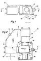
- X-Y shifting mechanism 30 is enclosed within a housing 32 having a mounting plate portion 34 with bolt bores 36 in a pattern allowing the mechanism 30 to be mounted at the upper opening in a transmission shift bar housing normally receiving the shift tower.
- a shift finger 38 extends downwardly from housing 32 for interaction with the shift rails.
- Housing 32 includes a portion 40 enclosing the select piston/cylinder assembly 42 for moving shift finger, axially or pivotably, in the direction of line X-X for selection of a selected shift rail, 12, 14 or 16; and a transversely extending portion 44 enclosing piston/cylinder assembly 46 for moving shift finger 38 in the direction of line Y-Y to cause axial movement of the selected shift rail and its associated shift fork for engaging or disengaging a selected transmission ratio gear.
- piston/cylinder assembly 46 is larger than piston/cylinder assembly 42 as moving shift finger 38 in the engagement, i.e. Y-Y, direction requires greater force than moving shift finger 38 in the selection, i.e. X-X, direction.
- Housing 32 also includes a valving portion 48 defining a single multiple pin electric connector 50, a single inlet 52 for connection to a source of pressurized fluid, such as a regulated, dried, filtered connection to the onboard vehicle air system, and a pressurized fluid exhaust to atmosphere 54.
- the valving portion 48 also contains the valves for controlling the X-X and Y-Y piston/cylinder assemblies, 42 and 46, respectively, a common pressurized fluid gallery 56 fluidly connected to inlet 52 and a common exhaust gallery 58 fluidly connected to the exhaust outlet 54.
- Housing 32 also defines a connector 60 for a neutral position sensor 62 and a pair of breather plugs 64 and 66 for the piston/cylinder assemblies. Other vent or breather plugs may be provided as necessary.
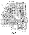
- the engagement/disengagement assembly 46 for moving shift finger 38 in the Y-Y axial direction comprises a shaft 68 supported as at sleeve bushings 70 for axial movement in the Y-Y direction, and pivotal movement, relative to housing 32.
- the shift finger 38 is integral with a shift finger carrier 72 axially and rotationally fixed to shaft 68 as by set screw 74.
- a piston 76 Adjacent its upper end, a piston 76 is axially fixed to shaft 68 between a shoulder 78 and a nut and washer 80 retained on threaded upper extension 82 of shaft 68. Piston 76 is slidably and sealingly received within cylinder member 84 to define sealed chambers 86 and 88. A piston 90 is slidably and sealingly received within a cylinder member 92. The piston 90 and cylinder 92 define a sealed chamber 94 above the piston. Downward axial movement of piston 90 is limited by washer shaped stop member 96 having a central opening 98 allowing the lower surface 100 of piston 90 to fluidly communicate with and define chamber 88 and to contact extension 82 of shaft 68.
- Piston 76 defines an upper and a lower surface 102 and 104, exposed to a pressure in chambers 88 and 86, respectively, which are smaller than the upper surface 106 and lower surface 100 of piston 90 exposed to fluid pressure in chambers 94 and 88, respectively. While surface 106 is equal in area to surface 100, at times when piston surface 100 is engaging stop member 96 or extension 82, the effective area of surface 106 exceeds that of surface 100.
- the piston/cylinder assembly 46 allows shaft 68 to assume any selected one of three selectable axial positions, namely axially centered as illustrated in Figure 3, an upward axial displacement wherein surface 102 will contact stop member 96 and a downward axial displacement wherein surface 104 contacts a stop member 108.
- the upward and downward displacements are selected in view of the required axial displacements of shift rails and associated shift forks to cause engagement and disengagement of transmission ratio gears.
- chambers 94 and 86 are pressurized while chamber 88 is exhausted.
- chambers 88 and 94 are pressurized while chamber 86 is exhausted. It is noted that chamber 94 could be exhausted to achieve the same but somewhat slower downward displacement.
- chamber 86 is pressurized while chambers 88 and 94 are exhausted.
- Movement of shift finger 38 in the X-X direction to align the shift finger with a selected shift rail is accomplished by selective axial positioning of shaft 110 which is slidably supported in housing 32 as by bushing 112 for movement substantially perpendicular to the axial movement of shaft 68. Except for being somewhat smaller in size, shaft 110 and its associated piston/cylinder assembly 42 is substantially functionally and structurally identical to that of shaft 68 and associated piston/cylinder assembly 46 described above.
- piston 114 is fixed to shaft 110 and defines sealed chambers 116 on 118 on the right and left faces, respectively, thereof.
- a larger piston for contact with a leftwardly extending extension of shaft 110 has a rightwardly facing surface exposed to pressure in chamber 118 and a leftwardly facing surface defining and exposed to fluid pressure in a sealed chamber 122.
- a first washer shaped stop member 124 limits rightward axial movement of piston 120 and leftward axial movement of piston 114. Stop member 126 limits rightward axial movement of piston 114.
- a crank mechanism 130 for pivoting shift finger in the X-X direction is controlled by shaft 110.
- a crank connector 132 is attached to shaft 110 as by set screw 134.
- the crank connector 132 includes a portion 136 axially offset but substantially parallel to shaft 110.
- Portion 136 defines a slot 138 for receipt of a generally bulbulous portion 140 defined by the shift finger carrier to define a ball and slotted socket type connection.
- the carrier 72 and shift finger 38 are thus a crank lever, pivotably movable about the axis 142 of shaft 68.
- shift finger 38 will align with the shift block 26 of shift rail 14. Movement of shaft 110 rightwardly will cause shift finger 38 to pivot to the position illustrated by phantom line 144 for alignment with shift block 28 of shift rail 16. Movement of shaft 110 leftwardly will cause the shift finger 38 to pivot to the position illustrated by phantom line 146 to align with shift block 24 of shift rail 12.
- Pressurization of chambers 122 and 116 and exhaust of chamber 118 will cause shaft 110 to assume the axially centered position of Figure 3. Pressurization of chamber 118, and preferably chamber 122, and exhaust of chamber 116 will cause shaft 110 to be axially displaced rightwardly. Pressurization of chamber 116 and exhaust of chambers 118 and 122 will cause shaft 110 to be displaced axially leftwardly.
- Pressurization and exhaust of each of the individual chambers 94, 88, 86, 116, 118 and 122, respectively, is controlled by one of the three-way two-position solenoid valves 150, 152, 154, 156, 158 and 160, respectively.
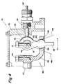
- the valves as illustrated in Figure 6, are of a standard type having a first port 162 connected to a common gallery 56 of pressurized fluid supplied by single-inlet connection 52, a second port 164 connected to common exhaust gallery 58 and a third port 166 connected to the individual chamber controlled by the valve.
- the valve is normally in the chamber exhaust position and, by action of the solenoid 168, is movable to the chamber pressurization position. Control of the various operating solenoids for the valves 150, 152, 154, 156, 158 and 160 is by the single electrical connector 50.
- a spring biased detent plunger 170 cooperates with a detent groove 172 to resiliently bias the finger 38 in the neutral condition and cooperates with sensor 62 to provide a neutral single to the transmission control unit.
- shaft 68 and thus shift finger 38, once positioned in a selective axial position will remain in that position even if all pressure to the various chambers is removed. Accordingly, especially if the shaft rails are provided with standard ingear and neutral detent devices, in the event of a pressure fluid failure, the X-Y shifter 30 will allow the engaged gear to remain engaged.
Landscapes
- Engineering & Computer Science (AREA)
- General Engineering & Computer Science (AREA)
- Mechanical Engineering (AREA)
- Gear-Shifting Mechanisms (AREA)
- Arrangement Or Mounting Of Control Devices For Change-Speed Gearing (AREA)
Claims (8)
- X-Y-Schaltvorrichtung (30) zum Steuern des Schaltens eines mechanischen Geschwindigkeitswechselgetriebes des Typs, der eine Schaltstangengehäuseanordnung (10) mit mehreren Schaltstangen (12, 14, 16) aufweist, die in ersten Richtungen (Y-Y) in einem Schaltstangengehäuse axial beweglich sind, wobei jede der Schaltstangen eine mit dieser verbundene Schaltgabel (18, 20, 22) sowie eine Kulisseneinrichtung (24, 26, 28) aufweist, die mit dem inneren Ende eines manuell betätigten Schalthebels kuppelbar ist, der in zweiten Richtungen (X-X) beweglich ist, die im wesentlichen rechtwinklig zu der ersten Richtung sind, um mit einer ausgewählten der Kulisseneinrichtungen in einer Linie ausgerichtet werden zu können, und der in der ersten Richtung bewegbar ist, um die ausgewählte der Schaltstangen von einer ersten axial nicht verschobenen Position in eine Zweite Position, die in eine Richtung entlang der ersten Achse (Y-X) verschoben ist, oder in eine zweite Position zu bewegen, die in die entgegengesetzte Richtung entlang der ersten Achse verschoben ist;
und der außerdem aufweist:
ein Schaltvorrichtungsgehäuse (32), das an dem Schaltstangengehäuse an dessen für den Schalthebel vorgesehenen Öffnung befestigbar ist, wobei sich ein Schaltfinger (38) von dem X-Y-Schaltvorrichtungsgehäuse (32) weg in Verlängerung durch die Öffnung und zum Zusammenwirken mit der Kulisseneinrichtung erstreckt;
eine erste Welle (68), die in der ersten axialen Richtung (Y-Y) in dem Schaltvorrichtungsgehäuse axial beweglich ist, wobei der Schaltfinger (38) an der ersten Welle (68) bezüglich der axialen Richtung fest verbunden ist, und wobei der Finger um die Achse (142) der ersten Welle dreh-beweglich ist;
eine zweite Welle (110), die in der zweiten axialen Richtung X-X in dem Schaltvorrichtungsgehäuse axial beweglich ist, wobei die zweite Welle Mittel (132) aufweist, die axial mit dieser beweglich sind und die den Schaltfinger an einem Punkt (140) berühren, der von der Achse (142) der ersten Welle beabstandet liegt, um diesen in eine erste, mit einer ersten Schaltstangenkulisseneinrichtung ausgerichtete Position, in eine zweite, mit einer zweiten Schaltstangenkulisseneinrichtung ausgerichtete Position und eine dritte, mit einer dritten Schaltstangenkulisseneinrichtung ausgerichtete Position zu bringen;
eine erste elektrisch gesteuerte durch ein unter Druck stehendes Fluid betätigte Stelleinrichtung (46) zum wahlweisen Positionieren der ersten Welle in irgendeine ausgewählte von drei unterschiedlichen auswählbaren Axialpositionen in der ersten Axialrichtung, wobei die erste Stelleinrichtung ein erstes Kolben- und Zylinderaggregat, das drei (86, 88, 94) wahlweise druckbeaufschlagte erste Kammern definiert, und drei elektrisch gesteuerte erste Ventile (150, 152, 154) zum wahlweisen und unabhängigen Druckbeaufschlagen und Druckentlasten der ersten Kammern aufweist; und
eine zweite elektrisch gesteuerte durch ein unter Druck stehendes Fluid betätigte Stelleinrichtung (42) zum wahlweisen Positionieren der zweiten Welle in irgendeine ausgewählte von drei unterschiedlichen auswählbaren Axialpositionen in der zweiten Axialrichtung, wobei die zweite Stelleinrichtung ein zweites Kolben- und Zylinderaggregat, das drei wahlweise druckbeaufschlagte und druckentlastete zweite Kammern (116, 118, 122) sowie drei elektrisch gesteuerte zweite Ventile (156, 158, 160) zum wahlweisen unabhängigen Druckbeaufschlagen und Druckentlasten der zweiten Kammern aufweist,
dadurch gekennzeichnet, daß;
die Schaltstangen (12, 14, 16) drei an der Zahl und im wesentlichen parallel sind;
die erste (68) und die zweite (110) Welle im wesentlichen in einer gemeinsamen Ebene liegen;
jedes der ersten und der zweiten Ventile jeweils einen ersten Anschluß (162), der mit einer gemeinsamen Quelle (56) für unter Druck stehende Fluide verbunden ist, einen zweiten Anschluß (164), der mit einem gemeinsamen Auslaß verbunden ist, und einen dritten Anschluß (166) aufweist, der mit der jeweiligen dadurch individuell gesteuerten Kammer verbunden ist, wobei die Ventile in Normalstellung den ersten Anschluß sperren und den zweiten und den dritten Anschluß für Fluide verbinden, und wobei die Ventile elektrisch steuerbar sind, um eine zweite Position anzunehmen, bei der der zweite Anschluß gesperrt ist und der erste mit dem dritten Anschluß für Fluide verbunden ist; und
wobei die gemeinsame Quelle (56) für unter Druck stehende Fluide einen abgedichteten Korridor in dem Vorrichtungsgehäuse (32) aufweist, der eine einzelne Fluidverbindung (52) von dem Gehäuse zu einer Quelle für unter Druck stehende Fluide aufweist; und
wobei der gemeinsame Auslaß ein Auslaßgang ist, der in Fluidverbindung mit einem Auslaßanschluß (54) steht. - X-Y-Schaltvorrichtung nach Anspruch 1, bei der die elektrisch gesteuerten Ventile (150, 152, 154, 156, 158, 160) von Magnetspulen (168) gesteuerte Ventile sind.
- X-Y-Schaltvorrichtung nach Anspruch 1 oder 2, bei der die Quelle für unter Druck stehendes Fluid ein Fahrzeugdruckluftsystem ist.
- X-Y-Schaltvorrichtung nach Anspruch 1, 2 oder 3, bei der jedes der Ventile einen ersten (180) und einen zweiten (182) elektrischen Anschluß hat, wobei alle der ersten Anschlüsse in Reihe geschaltet sind, wobei eine separate Verbindung für jeden zweiten Anschluß (182) vorgesehen ist und eine einzelne äußere elektrische Verbindungseinrichtung (50) wenigsten sieben voneinander unabhängige Verbinder in dem Gehäuse hat.
- X-Y-Schaltvorrichtung nach Anspruch 1, bei der das Mittel (132), das mit der zweiten Welle axial beweglich ist, um mit dem Schaltfinger (38) in Kontakt zu stehen, einen Schlitz (138) definiert, der sich in der ersten Axialrichtung ersteckt, um mit einem verdickten Abschnitt (140) zusammenzuwirken, der an dem Schaltfinger definiert ist.
- X-Y-Schaltvorrichtung nach Anspruch 1, bei der der Schaltfinger (38) drehfest mit der ersten Welle (68) verbunden und die erste Welle drehbar in dem Gehäuse gelagert ist.
- X-Y-Schaltvorrichtung nach Anspruch 1, bei der die erste (68) und die zweite (110) Welle axial in einer gemeinsamen Ebene beweglich sind und das Mittel (132), das an der zweiten Welle axial fixiert ist, eine gekröpfte Verbindung aufweist.
- X-Y-Schaltvorrichtung nach Anspruch 3, bei der alle der ersten und zweiten Ventile (150, 152, 154, 156, 158, 160) bei dem Gehäuse (32) angeordnet sind.
Applications Claiming Priority (2)
| Application Number | Priority Date | Filing Date | Title |
|---|---|---|---|
| GB878725981A GB8725981D0 (en) | 1987-11-05 | 1987-11-05 | X-y shifting mechanism |
| GB8725981 | 1987-11-05 |
Publications (3)
| Publication Number | Publication Date |
|---|---|
| EP0315347A2 EP0315347A2 (de) | 1989-05-10 |
| EP0315347A3 EP0315347A3 (en) | 1990-08-29 |
| EP0315347B1 true EP0315347B1 (de) | 1993-09-08 |
Family
ID=10626512
Family Applications (1)
| Application Number | Title | Priority Date | Filing Date |
|---|---|---|---|
| EP88309969A Expired - Lifetime EP0315347B1 (de) | 1987-11-05 | 1988-10-24 | Elektrisch gesteuerter und hydraulisch betätigter X-Y-Schaltmechanismus |
Country Status (8)
| Country | Link |
|---|---|
| US (1) | US4899607A (de) |
| EP (1) | EP0315347B1 (de) |
| JP (1) | JPH01153849A (de) |
| AU (1) | AU611362B2 (de) |
| BR (1) | BR8805679A (de) |
| DE (1) | DE3883917T2 (de) |
| ES (1) | ES2058307T3 (de) |
| GB (1) | GB8725981D0 (de) |
Families Citing this family (63)
| Publication number | Priority date | Publication date | Assignee | Title |
|---|---|---|---|---|
| GB8829074D0 (en) * | 1988-12-13 | 1989-01-25 | Eaton Gmbh | Shifting system for change speed transmission |
| GB8901605D0 (en) * | 1989-01-25 | 1989-03-15 | Eaton Corp | Emergency device |
| DE69001027T2 (de) * | 1989-02-11 | 1993-09-30 | Eaton Corp | Fühleranordnung für die Leerlaufstellung. |
| US4928544A (en) * | 1989-06-19 | 1990-05-29 | Eaton Corporation | Dual pressure pressurized fluid actuated shifting mechanism |
| GB9006091D0 (en) * | 1990-03-17 | 1990-05-16 | Eaton Corp | Transducer fault test logic |
| FR2660392B1 (fr) * | 1990-03-30 | 1992-05-29 | Valeo | Dispositif de commande motorise de changement de rapport de transmission pour boite de vitesses, en particulier pour vehicules automobiles. |
| JPH04113075A (ja) * | 1990-08-31 | 1992-04-14 | Isuzu Motors Ltd | 電子制御式変速機 |
| US5109729A (en) * | 1991-05-09 | 1992-05-05 | Eaton Corporation | Throttle control fault detection and tolerance method/system |
| US5109721A (en) * | 1991-05-09 | 1992-05-05 | Eaton Corporation | Range shifting only fault tolerance method/system |
| US5136897A (en) * | 1991-05-09 | 1992-08-11 | Eaton Corporation | Smooth upshift control method/system |
| US5274553A (en) * | 1991-05-09 | 1993-12-28 | Eaton Corporation | Torque converter slip rate based skip power downshift control strategy |
| US5099711A (en) * | 1991-05-09 | 1992-03-31 | Eaton Corporation | Tooth butt/buzz control method/system |
| US5305213A (en) * | 1991-05-09 | 1994-04-19 | Eaton Corporation | Driveline torque limit control strategy-using SAE J1922 type engine control |
| IT1251250B (it) * | 1991-11-08 | 1995-05-05 | Iveco Fiat | Cambio di velocita' per un veicolo industriale provvisto di un'unita' di comando integrata. |
| US5191804A (en) * | 1992-07-23 | 1993-03-09 | Eaton Corporation | Dual force fluid actuated shift device |
| US5279172A (en) * | 1992-10-22 | 1994-01-18 | Eaton Corporation | Four position fluid-actuated piston arrangement |
| US5305240A (en) * | 1992-11-25 | 1994-04-19 | Eaton Corporation | Computer controlled method of calibrating an x-y shifter |
| GB9304318D0 (en) * | 1993-03-03 | 1993-04-21 | Eaton Corp | Three-position shift actuator |
| DE4311855A1 (de) * | 1993-04-10 | 1994-10-13 | Hydraulik Ring Gmbh | Stellantriebssystem für Schaltgetriebe von Kraftfahrzeugen |
| US5389053A (en) * | 1993-07-21 | 1995-02-14 | Eaton Corporation | System and method for sliding clutch engagement under tooth butt or torque lock conditions |
| US5425284A (en) * | 1993-09-07 | 1995-06-20 | Eaton Corporation | Automated mechanical transmission control system/method |
| US5413012A (en) * | 1993-09-07 | 1995-05-09 | Eaton Corporation | Variable synchronous window |
| US5408898A (en) * | 1993-11-10 | 1995-04-25 | Eaton Corporation | Preselect shift strategy using stored energy |
| GB9412805D0 (en) | 1994-06-25 | 1994-08-17 | Eaton Corp | Engagement fault degraded mode control |
| GB9412809D0 (en) | 1994-06-25 | 1994-08-17 | Eaton Corp | Splitter section engagement control |
| GB9415861D0 (en) | 1994-08-05 | 1994-09-28 | Eaton Corp | Start gear ratio selection system and method |
| GB9415965D0 (en) | 1994-08-06 | 1994-09-28 | Eaton Corp | Continuous selection control for semi-automatic mechanical transmission |
| GB9416840D0 (en) | 1994-08-19 | 1994-10-12 | Eaton Corp | Downshift logic for semi-automatic mechanical transmission with manual clutch controller |
| US5634867A (en) | 1994-09-19 | 1997-06-03 | Eaton Corporation | Main clutch reengagement control for a double clutch downshift |
| US5566070A (en) * | 1995-02-02 | 1996-10-15 | Eaton Corporation | Transmission shift control including deflection-type neutral signal error detection and response |
| US5941137A (en) * | 1995-08-11 | 1999-08-24 | Siemens Aktiengesellschaft | Controller for a motor vehicle with an automatic transmission |
| DE19539472A1 (de) * | 1995-10-24 | 1997-04-30 | Zahnradfabrik Friedrichshafen | Schaltvorrichtung für Kraftfahrzeug-Wechselgetriebe - Pneumatischer Schaltservo - |
| GB9525055D0 (en) | 1995-12-07 | 1996-02-07 | Eaton Corp | Controled for automated mechanical transmission system |
| US5875410A (en) | 1996-01-12 | 1999-02-23 | Eaton Corporation | Dynamic best gear selection for automated transmission system |
| US5661998A (en) * | 1996-02-06 | 1997-09-02 | Eaton Corporation | Three-position actuator piston assembly and actuator system utilizing same |
| DE19604948A1 (de) * | 1996-02-10 | 1997-08-14 | Telefunken Microelectron | Steuerungsanordnung für ein automatisches elektrohydraulisch gesteuertes Getriebe |
| DE19606756A1 (de) * | 1996-02-23 | 1997-08-28 | Hydraulik Ring Gmbh | Stelleinrichtung zur Automatisierung von Handschaltgetrieben von Kraftfahrzeugen |
| DE19615267C1 (de) * | 1996-04-18 | 1997-06-12 | Getrag Getriebe Zahnrad | Schaltanordnung für ein automatisiertes Handschaltgetriebe |
| US5743143A (en) * | 1996-08-09 | 1998-04-28 | Eaton Corporation | Transmission shifting mechanism and position sensor |
| GB9721823D0 (en) | 1997-10-16 | 1997-12-17 | Eaton Corp | Shift into optimal engine braking control system and method |
| US6000294A (en) * | 1997-11-15 | 1999-12-14 | Eaton Corporation | System and method for fluid assisted shifting of mechanical transmissions |
| US5911787A (en) | 1998-04-01 | 1999-06-15 | Eaton Corporation | Dynamic range shift actuation |
| US5950491A (en) | 1998-04-01 | 1999-09-14 | Eaton Corporation | Adaptive neutral sensing |
| US5989155A (en) | 1998-04-01 | 1999-11-23 | Eaton Corporation | Engine fuel control for completing shifts in controller-assisted, manually shifted transmission |
| JPH11287321A (ja) * | 1998-04-01 | 1999-10-19 | Aisin Ai Co Ltd | 自動t/m用シフトアクチュエータの油圧回路 |
| US5974906A (en) | 1998-04-01 | 1999-11-02 | Eaton Corporation | Jaw clutch engagement control for assisted, manually shifted, splitter-type transmission system |
| US5970810A (en) | 1998-04-01 | 1999-10-26 | Eaton Corporation | Adaptive splitter actuator engagement force control |
| US5984831A (en) | 1998-04-01 | 1999-11-16 | Eaton Corporation | Adaptive upshift jaw clutch engagement control |
| US6042504A (en) | 1998-04-01 | 2000-03-28 | Eaton Corporation | Range shift control |
| US5992267A (en) | 1998-10-26 | 1999-11-30 | Eaton Corporation | Robust control for three-position transmission shift actuator assembly |
| US6658339B1 (en) | 1999-11-26 | 2003-12-02 | Eaton Corporation | Driver-programmable driving mode system for automatic transmissions |
| US6301537B1 (en) | 2000-06-05 | 2001-10-09 | Eaton Corporation | Adaptive calibration of X-Y position sensor |
| GB2384533A (en) * | 2002-01-25 | 2003-07-30 | Eaton Corp | Gear shift cassette housing |
| CN101046250B (zh) * | 2006-03-31 | 2010-05-12 | 上海盈达信汽车电子有限公司 | 一种电控液动自动变速作动器 |
| US7905812B2 (en) * | 2007-02-02 | 2011-03-15 | Eaton Corporation | PTO brake |
| JP4903674B2 (ja) * | 2007-11-20 | 2012-03-28 | 京浜精密工業株式会社 | 変速操作機構 |
| US8046140B2 (en) | 2008-01-18 | 2011-10-25 | Eaton Corporation | PTO overspeed protection strategy |
| CN103185135B (zh) * | 2011-12-29 | 2015-04-29 | 广西玉柴机器股份有限公司 | 电控机械式自动变速器的驱动机构 |
| US20140165767A1 (en) * | 2012-12-19 | 2014-06-19 | Deere And Company | Manual synchronized gear shift assist |
| KR101986520B1 (ko) * | 2017-09-15 | 2019-06-10 | 명화공업주식회사 | 액추에이터 피스톤 조립체 |
| KR101994654B1 (ko) * | 2017-09-15 | 2019-07-02 | 명화공업주식회사 | 액추에이터 피스톤 조립체의 스토퍼 구조 |
| KR101994652B1 (ko) * | 2017-09-15 | 2019-07-02 | 명화공업주식회사 | 액추에이터 피스톤 조립체의 유체 공급 구조 |
| CN118499312B (zh) * | 2024-07-18 | 2024-09-13 | 中国科学院沈阳科学仪器股份有限公司 | 一种三位置气缸及其使用方法 |
Family Cites Families (18)
| Publication number | Priority date | Publication date | Assignee | Title |
|---|---|---|---|---|
| US2137953A (en) * | 1936-11-04 | 1938-11-22 | Bendix Westinghouse Automotive | Control mechanism |
| US2951392A (en) * | 1957-11-01 | 1960-09-06 | Fuller Mfg Co | Automotive device |
| US2931237A (en) * | 1957-12-02 | 1960-04-05 | Fuller Mfg Co | Automotive device |
| US3039321A (en) * | 1958-01-31 | 1962-06-19 | Weymann Charles Terres | Automatic drive |
| DE1113620B (de) * | 1958-07-16 | 1961-09-07 | Magneti Marelli Spa | Vorwaehl- und Schaltvorrichtung fuer Zahnraederwechselgetriebe |
| US3093008A (en) * | 1959-08-18 | 1963-06-11 | Huntly Engineering & Welding C | Remote control for auxiliary transmissions |
| FR1432945A (fr) * | 1964-04-15 | 1966-03-25 | Turner Mfg Co Ltd | Mécanisme de commande d'embrayage, notamment de boîtes de changement de vitesse d'automobiles |
| DE1505535C3 (de) * | 1966-01-27 | 1978-09-21 | Robert Bosch Gmbh, 7000 Stuttgart | Selbsttätige elektrische Steuereinrichtung für ein Kraftfahrzeug-Zahnräderwechselgetriebe |
| DE2124624A1 (de) * | 1971-05-18 | 1972-12-07 | Robert Bosch Gmbh, 7000 Stuttgart | Gangschaltvorrichtung |
| GB1572317A (en) * | 1978-03-30 | 1980-07-30 | Eaton Ltd | Shift control for change speed gear transmission for vehicles |
| GB2087991A (en) * | 1980-11-14 | 1982-06-03 | Eaton Ltd | Combined shift control |
| US4515029A (en) * | 1982-11-08 | 1985-05-07 | Eaton Corporation | Compound variable mechanical advantage shifting mechanism |
| JPS6011752A (ja) * | 1983-06-29 | 1985-01-22 | Isuzu Motors Ltd | 自動歯車変速機の安全装置 |
| US4625840A (en) * | 1983-08-19 | 1986-12-02 | Diesel Kiki Co., Ltd. | Hydraulic control unit for automotive transmissions |
| FR2556291B1 (fr) * | 1983-12-09 | 1988-10-28 | France Etat Armement | Installation de commande a distance d'une boite de vitesses, du type mecanique |
| US4567785A (en) * | 1983-12-16 | 1986-02-04 | Eaton Corporation | Directly mounted master shift control |
| US4584895A (en) * | 1984-06-11 | 1986-04-29 | Eaton Corporation | Transmission shift control |
| DE3429531A1 (de) * | 1984-08-10 | 1986-02-20 | Wabco Westinghouse Fahrzeugbremsen GmbH, 3000 Hannover | Hilfskraftbetaetigtes fahrzeuggetriebe |
-
1987
- 1987-11-05 GB GB878725981A patent/GB8725981D0/en active Pending
-
1988
- 1988-10-24 US US07/261,454 patent/US4899607A/en not_active Expired - Fee Related
- 1988-10-24 BR BR888805679A patent/BR8805679A/pt not_active IP Right Cessation
- 1988-10-24 EP EP88309969A patent/EP0315347B1/de not_active Expired - Lifetime
- 1988-10-24 DE DE88309969T patent/DE3883917T2/de not_active Expired - Fee Related
- 1988-10-24 ES ES88309969T patent/ES2058307T3/es not_active Expired - Lifetime
- 1988-10-31 JP JP63275958A patent/JPH01153849A/ja active Pending
- 1988-11-04 AU AU24689/88A patent/AU611362B2/en not_active Ceased
Also Published As
| Publication number | Publication date |
|---|---|
| JPH01153849A (ja) | 1989-06-16 |
| DE3883917T2 (de) | 1994-03-24 |
| AU2468988A (en) | 1989-05-11 |
| US4899607A (en) | 1990-02-13 |
| AU611362B2 (en) | 1991-06-06 |
| EP0315347A2 (de) | 1989-05-10 |
| EP0315347A3 (en) | 1990-08-29 |
| ES2058307T3 (es) | 1994-11-01 |
| GB8725981D0 (en) | 1987-12-09 |
| BR8805679A (pt) | 1989-07-18 |
| DE3883917D1 (de) | 1993-10-14 |
Similar Documents
| Publication | Publication Date | Title |
|---|---|---|
| EP0315347B1 (de) | Elektrisch gesteuerter und hydraulisch betätigter X-Y-Schaltmechanismus | |
| EP0403777B1 (de) | Zweifach wirkender, hydraulisch betätigter Schaltmechanismus | |
| EP0271234B1 (de) | Gehäuse für druckmittelbetätigte Schaltstange | |
| EP0377848B1 (de) | Elektrisch betätigte X-Y-Schalteinrichtung | |
| EP0614030B1 (de) | Schaltzylinder für drei Schaltstellungen | |
| EP0052814B1 (de) | Steuerung und Mechanismus zum Verbringen eines Hilfsgetriebes in die Leerlaufstellung und zum Verriegeln in derselben | |
| EP0541035B1 (de) | Getriebeschaltung für Industriefahrzeuge mit integrierter Steuereinheit | |
| EP0592170B1 (de) | Getriebeeinheit | |
| CA1220648A (en) | Transmission shift rod interlock system | |
| EP0127949B1 (de) | Getriebe-Schaltsystem | |
| KR920000036B1 (ko) | 보조변속기 기어변경 조정장치 | |
| EP0387275B1 (de) | Steuersystem für automatisches getriebe, in dem der gangwechsel stufenweise erfolgt | |
| GB2214248A (en) | Ratio selector system using fluid actuators and ectrohydraulic control in a vehicle transmission | |
| EP0580332B1 (de) | Druckmittelbetätigte Schaltvorrichtung mit zwei Kräften | |
| US5992267A (en) | Robust control for three-position transmission shift actuator assembly | |
| US3470759A (en) | Power-assisted change-speed devices | |
| CA2053682C (en) | Auxiliary transmission shift control system | |
| USRE34260E (en) | Dual pressure pressurized fluid actuated shifting mechanism | |
| US4930366A (en) | Electrical transmission control mechanism | |
| GB2057607A (en) | Arrangement for Blocking a Vehicle Clutch | |
| EP1010925B1 (de) | Ventilsteuerungssystem für eine Gruppenschaltung eines Splitter-Verbundgetriebes | |
| US20020173405A1 (en) | Gear actuator for engaging and/or disengaging gears of a transmission | |
| US5279172A (en) | Four position fluid-actuated piston arrangement | |
| SU1471015A1 (ru) | Система дистанционного управлени коробкой передач |
Legal Events
| Date | Code | Title | Description |
|---|---|---|---|
| PUAI | Public reference made under article 153(3) epc to a published international application that has entered the european phase |
Free format text: ORIGINAL CODE: 0009012 |
|
| AK | Designated contracting states |
Kind code of ref document: A2 Designated state(s): DE ES FR GB IT SE |
|
| PUAL | Search report despatched |
Free format text: ORIGINAL CODE: 0009013 |
|
| AK | Designated contracting states |
Kind code of ref document: A3 Designated state(s): DE ES FR GB IT SE |
|
| 17P | Request for examination filed |
Effective date: 19901201 |
|
| 17Q | First examination report despatched |
Effective date: 19920319 |
|
| GRAA | (expected) grant |
Free format text: ORIGINAL CODE: 0009210 |
|
| AK | Designated contracting states |
Kind code of ref document: B1 Designated state(s): DE ES FR GB IT SE |
|
| ITF | It: translation for a ep patent filed | ||
| REF | Corresponds to: |
Ref document number: 3883917 Country of ref document: DE Date of ref document: 19931014 |
|
| ET | Fr: translation filed | ||
| PLBE | No opposition filed within time limit |
Free format text: ORIGINAL CODE: 0009261 |
|
| STAA | Information on the status of an ep patent application or granted ep patent |
Free format text: STATUS: NO OPPOSITION FILED WITHIN TIME LIMIT |
|
| 26N | No opposition filed | ||
| REG | Reference to a national code |
Ref country code: ES Ref legal event code: FG2A Ref document number: 2058307 Country of ref document: ES Kind code of ref document: T3 |
|
| EAL | Se: european patent in force in sweden |
Ref document number: 88309969.9 |
|
| PGFP | Annual fee paid to national office [announced via postgrant information from national office to epo] |
Ref country code: GB Payment date: 19970917 Year of fee payment: 10 |
|
| PGFP | Annual fee paid to national office [announced via postgrant information from national office to epo] |
Ref country code: SE Payment date: 19971006 Year of fee payment: 10 |
|
| PGFP | Annual fee paid to national office [announced via postgrant information from national office to epo] |
Ref country code: FR Payment date: 19971007 Year of fee payment: 10 |
|
| PGFP | Annual fee paid to national office [announced via postgrant information from national office to epo] |
Ref country code: ES Payment date: 19971021 Year of fee payment: 10 |
|
| PGFP | Annual fee paid to national office [announced via postgrant information from national office to epo] |
Ref country code: DE Payment date: 19971030 Year of fee payment: 10 |
|
| PG25 | Lapsed in a contracting state [announced via postgrant information from national office to epo] |
Ref country code: GB Free format text: LAPSE BECAUSE OF NON-PAYMENT OF DUE FEES Effective date: 19981024 |
|
| PG25 | Lapsed in a contracting state [announced via postgrant information from national office to epo] |
Ref country code: SE Free format text: LAPSE BECAUSE OF NON-PAYMENT OF DUE FEES Effective date: 19981025 Ref country code: ES Free format text: LAPSE BECAUSE OF NON-PAYMENT OF DUE FEES Effective date: 19981025 |
|
| GBPC | Gb: european patent ceased through non-payment of renewal fee |
Effective date: 19981024 |
|
| EUG | Se: european patent has lapsed |
Ref document number: 88309969.9 |
|
| PG25 | Lapsed in a contracting state [announced via postgrant information from national office to epo] |
Ref country code: FR Free format text: LAPSE BECAUSE OF NON-PAYMENT OF DUE FEES Effective date: 19990630 |
|
| REG | Reference to a national code |
Ref country code: FR Ref legal event code: ST |
|
| PG25 | Lapsed in a contracting state [announced via postgrant information from national office to epo] |
Ref country code: DE Free format text: LAPSE BECAUSE OF NON-PAYMENT OF DUE FEES Effective date: 19990803 |
|
| REG | Reference to a national code |
Ref country code: ES Ref legal event code: FD2A Effective date: 19991113 |
|
| PG25 | Lapsed in a contracting state [announced via postgrant information from national office to epo] |
Ref country code: IT Free format text: LAPSE BECAUSE OF NON-PAYMENT OF DUE FEES;WARNING: LAPSES OF ITALIAN PATENTS WITH EFFECTIVE DATE BEFORE 2007 MAY HAVE OCCURRED AT ANY TIME BEFORE 2007. THE CORRECT EFFECTIVE DATE MAY BE DIFFERENT FROM THE ONE RECORDED. Effective date: 20051024 |