EP0052814B1 - Steuerung und Mechanismus zum Verbringen eines Hilfsgetriebes in die Leerlaufstellung und zum Verriegeln in derselben - Google Patents
Steuerung und Mechanismus zum Verbringen eines Hilfsgetriebes in die Leerlaufstellung und zum Verriegeln in derselben Download PDFInfo
- Publication number
- EP0052814B1 EP0052814B1 EP81109445A EP81109445A EP0052814B1 EP 0052814 B1 EP0052814 B1 EP 0052814B1 EP 81109445 A EP81109445 A EP 81109445A EP 81109445 A EP81109445 A EP 81109445A EP 0052814 B1 EP0052814 B1 EP 0052814B1
- Authority
- EP
- European Patent Office
- Prior art keywords
- ram
- piston
- control
- locking
- positioning
- Prior art date
- Legal status (The legal status is an assumption and is not a legal conclusion. Google has not performed a legal analysis and makes no representation as to the accuracy of the status listed.)
- Expired
Links
- 230000005540 biological transmission Effects 0.000 title claims description 81
- 230000007935 neutral effect Effects 0.000 title claims description 42
- 230000007246 mechanism Effects 0.000 title description 8
- 150000001875 compounds Chemical class 0.000 claims description 13
- 239000012530 fluid Substances 0.000 claims description 13
- 230000008859 change Effects 0.000 claims description 9
- 239000003112 inhibitor Substances 0.000 claims description 9
- 238000013022 venting Methods 0.000 claims description 9
- 230000033001 locomotion Effects 0.000 claims description 8
- 230000000295 complement effect Effects 0.000 claims description 3
- 230000004044 response Effects 0.000 claims description 3
- 238000012544 monitoring process Methods 0.000 claims 2
- 230000003213 activating effect Effects 0.000 claims 1
- 230000013011 mating Effects 0.000 claims 1
- 230000001105 regulatory effect Effects 0.000 description 5
- 230000000903 blocking effect Effects 0.000 description 2
- 230000009467 reduction Effects 0.000 description 2
- 230000001276 controlling effect Effects 0.000 description 1
- 230000008676 import Effects 0.000 description 1
- 230000000717 retained effect Effects 0.000 description 1
- 230000009528 severe injury Effects 0.000 description 1
Images


Classifications
-
- F—MECHANICAL ENGINEERING; LIGHTING; HEATING; WEAPONS; BLASTING
- F16—ENGINEERING ELEMENTS AND UNITS; GENERAL MEASURES FOR PRODUCING AND MAINTAINING EFFECTIVE FUNCTIONING OF MACHINES OR INSTALLATIONS; THERMAL INSULATION IN GENERAL
- F16H—GEARING
- F16H63/00—Control outputs from the control unit to change-speed- or reversing-gearings for conveying rotary motion or to other devices than the final output mechanism
- F16H63/40—Control outputs from the control unit to change-speed- or reversing-gearings for conveying rotary motion or to other devices than the final output mechanism comprising signals other than signals for actuating the final output mechanisms
- F16H63/44—Signals to the control unit of auxiliary gearing
-
- F—MECHANICAL ENGINEERING; LIGHTING; HEATING; WEAPONS; BLASTING
- F16—ENGINEERING ELEMENTS AND UNITS; GENERAL MEASURES FOR PRODUCING AND MAINTAINING EFFECTIVE FUNCTIONING OF MACHINES OR INSTALLATIONS; THERMAL INSULATION IN GENERAL
- F16H—GEARING
- F16H3/00—Toothed gearings for conveying rotary motion with variable gear ratio or for reversing rotary motion
- F16H3/02—Toothed gearings for conveying rotary motion with variable gear ratio or for reversing rotary motion without gears having orbital motion
- F16H3/08—Toothed gearings for conveying rotary motion with variable gear ratio or for reversing rotary motion without gears having orbital motion exclusively or essentially with continuously meshing gears, that can be disengaged from their shafts
- F16H3/087—Toothed gearings for conveying rotary motion with variable gear ratio or for reversing rotary motion without gears having orbital motion exclusively or essentially with continuously meshing gears, that can be disengaged from their shafts characterised by the disposition of the gears
- F16H3/093—Toothed gearings for conveying rotary motion with variable gear ratio or for reversing rotary motion without gears having orbital motion exclusively or essentially with continuously meshing gears, that can be disengaged from their shafts characterised by the disposition of the gears with two or more countershafts
- F16H3/095—Toothed gearings for conveying rotary motion with variable gear ratio or for reversing rotary motion without gears having orbital motion exclusively or essentially with continuously meshing gears, that can be disengaged from their shafts characterised by the disposition of the gears with two or more countershafts with means for ensuring an even distribution of torque between the countershafts
-
- Y—GENERAL TAGGING OF NEW TECHNOLOGICAL DEVELOPMENTS; GENERAL TAGGING OF CROSS-SECTIONAL TECHNOLOGIES SPANNING OVER SEVERAL SECTIONS OF THE IPC; TECHNICAL SUBJECTS COVERED BY FORMER USPC CROSS-REFERENCE ART COLLECTIONS [XRACs] AND DIGESTS
- Y10—TECHNICAL SUBJECTS COVERED BY FORMER USPC
- Y10T—TECHNICAL SUBJECTS COVERED BY FORMER US CLASSIFICATION
- Y10T74/00—Machine element or mechanism
- Y10T74/19—Gearing
- Y10T74/19167—In series plural interchangeably locked nonplanetary units
-
- Y—GENERAL TAGGING OF NEW TECHNOLOGICAL DEVELOPMENTS; GENERAL TAGGING OF CROSS-SECTIONAL TECHNOLOGIES SPANNING OVER SEVERAL SECTIONS OF THE IPC; TECHNICAL SUBJECTS COVERED BY FORMER USPC CROSS-REFERENCE ART COLLECTIONS [XRACs] AND DIGESTS
- Y10—TECHNICAL SUBJECTS COVERED BY FORMER USPC
- Y10T—TECHNICAL SUBJECTS COVERED BY FORMER US CLASSIFICATION
- Y10T74/00—Machine element or mechanism
- Y10T74/20—Control lever and linkage systems
- Y10T74/20012—Multiple controlled elements
- Y10T74/20018—Transmission control
- Y10T74/20085—Restriction of shift, gear selection, or gear engagement
- Y10T74/20098—Separate actuator to disengage restrictor
Definitions
- the present invention relates to a transmission control for a compound change gear transmission, having a main change speed gear group and an auxiliary change speed gear group connected in series therewith, comprising: a main gear group, shifting control for shifting said main gear group to one of a plurality of selectable gear ratios or into neutral; an auxiliary gear group shifting control for shifting said auxiliary gear group into one of a plurality of selectable gear ratios, said auxiliary shifting control comprising an axially movable control member having a first axial position for shifting said auxiliary gear group into a first selected gear ratio and a second axial position for shifting said auxiliary gear group into a second selected gear ratio.
- Compound change gear transmissions of the type comprising a main transmission section in series with an auxiliary transmission section, usually for vehicles, are well known in the prior art.
- the auxiliary transmission sections usually comprised at least one auxiliary countershaft driven by the main transmission section and an auxiliary output shaft or mainshaft which was selectively clutchable to the auxiliary countershafts and/or directly to the auxiliary input.
- the main transmission section was directly shifted (as by a shift bar linkage assembly) or shifted through air or hydraulic valving, while the auxiliary transmission section was shifted by a master-slave valve control. Examples of such transmissions and controls can be seen by reference to U.S. Patent Nos. 3,171,300; 3,283,613; 3,648,546; 3,799,002 and 4,192,196, all assigned to the assignee of this invention and all hereby incorporated by reference.
- auxiliary countershafts can be utilized to drive added devices independently of the auxiliary output shaft, i.e. with the vehicle stationary, as through an auxiliary countershaft power take-off ("PTO") or the like. If the added device is to be driven while the vehicle is at rest, the main transmission section must be engaged to supply power to the auxiliary countershaft while the auxiliary mainshaft, or output shaft, must be disengaged, i.e. the auxiliary section must be in neutral.
- PTO auxiliary countershaft power take-off
- GB-A-2 019 509 which reveals all features of the precharacterizing part of claim 1 shows an arrangement for preventing incorrect shifting in a compound change gear transmission, having a main portion with a number of gear ratios and a two-speed auxiliary portion.
- the compound transmission provides such a gear ratio that the total gear ratio of the transmission, when the higher gear ratio of the auxiliary portion is used together with the lowest gear ratio of the main portion, is higher than when the lower gear ratio of the auxiliary portion is used together with the highest gear ratio of the main portion.
- a blocking system which blocks the shift lever of the main portion in its neutral position until the shifting of the auxiliary portion is completed.
- the blocking system includes a pressure medium operated piston cylinder device and a series of valves for controlling the movement of the piston, depending on the speed of the output shaft of the transmission and the movement of the selector mechanism of the auxiliary portion.
- the piston carries a ram which is designed to come into engagement with a recess of the shaft on which the shift lever is mounted when the shifting of the main portion requires another range of the auxiliary portion.
- compound transmission is used to designate a transmission having a main transmission portion and an auxiliary transmission portion connected in series therewith whereby the selected gear reduction in the main transmission portion may be compounded by further selected gear reduction in the auxiliary transmission portion.
- a shiftable, compound change speed transmission 11 having both a main transmission section 12 and an auxiliary transmission section 13, each of which have a plurality of selectable speeds or ratios.
- the transmission illustrated is generally referred to in the art as a compound transmission and may be of the splitter type of compound transmission, or of the range type of compound transmission or a combination thereof.
- the main and auxiliary sections are both suitably enclosed by conventional housing means (not shown).
- the transmission 11 includes an input shaft 16 provided with an input gear 18 non-rotatably; connected thereto, as by splines.
- the input gear 18 simultaneously drives a plurality of countershafts at equal speeds.
- the transmission is provided with two substantially identical countershafts, 21 and 22, disposed on diametrically opposite sides of the mainshaft 23. It is understood that the present invention is intended for use with transmissions utilizing single as well as multiple countershafts.
- the input shaft 16 is normally driven in one direction of rotation only by a primemover, such as a Diesel engine E through a selectively operated, normally engaged, friction master clutch C.
- Clutch C may be disengaged by use of pedal P as is known in the prior art.
- Each of the countershafts, 21 and 22, is provided with an identical grouping of countershaft gears, 25, 26, 27 and 28, which groupings form pairs of gears, such as the pair of gears 26, of identical size and number of teeth and disposed on diametrically opposite sides of mainshaft 23.
- the mainshaft gears, 31, 32 and 33, encircle the mainshaft 23, are in continuous meshing engagement with, and are floatingly supported by the diametrically opposite pairs of countershaft gears 26, 27 and 28, respectively, which mounting means and the special advantages resulting therefrom are explained in greater detail in U.S. Patent Nos. 3,105,395 and 3,335,616, both assigned to the assignee of this application and both hereby incorporated by reference.
- An additional pair of countershaft gears (not shown) engaged with idler gears (not shown) which in turn are engaged with an additional mainshaft gear (not shown) may be provided for providing a selective reverse operation as is well known in the prior art.
- the forwardmost countershaft gears 25 are continually meshed with and driven by the input gear 18 for causing simultaneous rotation of the countershafts, 21 and 22, whenever the input shaft is rotatably driven.
- a first sliding clutch 35 is slidably retained on mainshaft 23, as by splines, and may be axially positioned by shift fork 36 to the neutral position shown, to the right to clutch mainshaft gear 33 to the mainshaft 23 or to the left to clutch mainshaft gear 32 to mainshaft 23.
- a second sliding clutch 37 is slidably received on the mainshaft 23 and may be selectively axially positioned by shift fork 38 to the neutral position shown, to the right to clutch mainshaft gear 31 to the mainshaft or to the left to clutch the input shaft 16 andlor input gear 18 directly to the mainshaft 23.
- Shift forks 36 and 38 are preferably controlled by a conventional shift bar assembly 40 which will include an interlock to prevent movement of one shift fork from the neutral position unless the other shift fork is also in the neutral position, as is well known in the art.
- the shift bar assembly will also include a means 42 for sensing when all main transmission shift forks are in an axially centered position, i.e. when the main transmission section is in neutral, and providing a signal in response thereto.
- Main transmission section countershafts, 21 and 22, are supported by bearings 44 and 46.
- the mainshaft 23 extends into the auxiliary transmission section 13 and an auxiliary input gear 48 is rotationally fixed thereto as by splines.
- a pair of auxiliary countershafts, 50 and 52 are constantly driven by the mainshaft 23 through auxiliary countershaft gears 54 fixed to the auxiliary countershafts and constantly meshed with the auxiliary input gear 48.
- An output shaft, or auxiliary mainshaft, 56 is provided substantially concentric with mainshaft 23.
- An auxiliary mainshaft gear 60 surrounds and is selectively clutchable to the output shaft 56.
- the auxiliary mainshaft gear 60 is supported by, and in constant mesh with, auxiliary countershaft gears 64 fixed to the auxiliary countershafts.
- the auxiliary countershafts are supported by bearings 66 and 68.
- a sliding clutch 70 is slidably received on the output shaft 56, as by splines, and is axially positioned by a shift fork 72.
- Shift fork 72 will normally bias the sliding clutch 70 to the right to clutch auxiliary mainshaft gear 60 to the output shaft 56 or to the left to clutch the output shaft 56 directly to the mainshaft 23 and/or the auxiliary input gear 48.
- the axial position of the mainshaft is normally to the right or the left of the position shown in response to actuation of a slave valve SV controlled by a master valve MV having a high ("H") or low (“L”) selection only.
- the master valve may be separate from or integral with the shift lever 74 of the shift bar housing 40.
- the shift fork 72 may be positioned and locked in the axially centered position shown in the drawing (i.e. the auxiliary transmission section in neutral) by means of the control 100 of the present invention to be discussed in detail below.
- a power take-off unit, PTO is driven by one of the auxiliary countershafts 52.
- the PTO may be constantly engaged to the auxiliary countershaft, or preferably, selectively drivingly engageable thereto.
- the main transmission section must be engaged and the auxiliary transmission section in neutral (i.e. shift fork 72 axially centered).
- the auxiliary transmission section 13 be prevented from accidently being engaged, as by accidental bumping of a control mechanism or the iike. It is also important that, when it is desirable to place the vehicle in motion, the auxiliary transmission be capable of being engaged in either the low or high (direct) drive mode.
- control system 100 of the present invention may be seen by reference to FIGS. 2 and 3.
- FIG. 2 An air or fluid control system 100 is schematically illustrated in FIG. 2. It is understood that a comparable mechanical and/or electrical control system may also be utilized within the scope of the present invention.
- a source 102 of pressurized fluid such as pressurized air, such as the vehicle air supply, is filtered and regulated at filter 104 and regulater 106.
- the air pressure is typically regulated to about 4. 4, 4 Bar.
- the regulated air is directed to a normally open pilot valve 108 via passage 110.
- the outlet of the pilot valve is, in the open condition, connected to a manually controlled auxiliary section master valve MV via passages 112 and 114 and to the auxiliary slave valve SV via passages 112 and 116.
- the slave valve SV will either connect passage 118 to passage 116 and exhaust passage 120, or connect passage 120 to passage 116 and exhaust passage 118 to bias the shift piston 122 in shift cylinder 124 to the left or to the right, respectively, to shift the shift fork 72.
- a mechanical inhibitor 126 will be forced to the right when the signal from sensor 42 indicates the main transmission section is in gear, (i.e. not in neutral) to engage mechanical interlock 148 to prevent movement of the slave valve until the main transmission is shifted to neutral causing the mechanical inhibitor to shift to the right (as shown in FIG. 2).
- Regulated air is also supplied to a two position, mobile-stationary selector valve 132 by passage 134.
- Mobile-stationary valve 132 is preferably located in the vehicle cab and allows the operator to selectively place the vehicle in a stationary condition or a condition permitting mobilization thereof (i.e. allowing the auxiliary transmission output shaft to be engaged).
- valve 132 In the mobile setting ("M”) of valve 132, passage 134 is connected to passage 136, and passage 138 is vented to exhaust. In the stationary setting (“S”) of valve 132, passage 134 is connected to passage 138 and passage 136 is vented to exhaust.
- Passage 136 is connected to a two-position neutral inhibitor valve 140.
- the neutral inhibitor valve 140 will connect passage 136 to passage 142 if the main transmisison is in neutral or will block passage 136 and vent passage 142 to atmosphere if the main transmission is not in neutral.
- Passage 138 is connected to passage 144 and, when pressurized, will cause the normally open pilot valve 108 to close, i.e. move upwardly from the position shown, and block passage 110 and to vent passage 112 to atmosphere. Passage 138 also connects to passage 146.
- Passage 142 and 146 lead to opposite ends of the positioning and locking cylinder 148. Pressurization of passage 146, and exhaust of passage 142 will cause the positioning and locking piston 150, in the cylinder 148, and the ram 151 axially movable therewith, to move upwardly to engage the positioning and locking block 152 fixed to shift piston 122 to position and lock shift fork 72 in a neutral position. Pressurization of passage 142 and exhaust of passage 146 will result in piston 150 and ram 151 being forced downwardly to disengage the block 152 thus allowing movement of the piston 122.
- Drag ring 154 on piston 150 will create a frictional drag between piston 150 and cylinder 148 to tend to retain the piston 150 in its current position in the event of loss of system air or a failure of passage 142 and/or 146.
- Drag ring 154 may be replaced by a spring biased detent, or the like, as is well known in the art.
- control 100 is as follows. Pressurized air from a source, such as the vehicle air system, is filtered and regulated and introduced to passages 110 and 134.
- a source such as the vehicle air system
- the stationary- mobile selector valve, 132 is placed in the stationary position ("S"), i.e. moved upwardly from the position illustrated in FIG. 2.
- S stationary position
- passage 134 is connected with passages 144 and 146 via passage 138 and passage 136 is vented.
- Pressurization of passage 144 will move the spring biased pilot valve 108 upwardly venting passage 112,114,116,118,120 and both sides of cylinder 124. Venting of passage 136 will vent passage 142 and the upper portion of cylinder 148.
- passage 146 Pressurization of passage 146 will force the piston and ram, 150, upwardly to engage the positioning and locking block 152 to position and lock the auxiliary shift fork 72 in a neutral position.
- the main transmission section may be shifted into a selected' gear ratio to drive the PTO with the output shaft 56 stationary.
- the frictional drag of the drag ring 154 on the cylinder 148 will maintain the piston 150 in its selected position in the event the air supply is interrupted.
- the range shift piston 122 and shift fork 72 may only be shifted back to an engaged position upon the occurrence of two events, namely the main transmission section shifted to, or remaining in, a neutral position at the same time that the selector valve 132 is placed in the mobile ("M") position, i.e. the position shown in FIG. 2. If the main transmission 12 is not shifted to neutral, the mechanical inhibitor, 126, will force the neutral inhibitor valve 140 to be spring biased to a position upward of that shown in FIG. 2 wherein passage 142 is vented and passage 136 is blocked.
- the inhibitor valve 140 When the main transmission is shifted into neutral, the inhibitor valve 140 assumes the position shown in FIG. 2 connecting passage 136 to passage 142. If the selector valve 132 is then placed in the mobile position as shown in FIG. 2, passages 138,144 and 146 are vented. This opens the normally open pilot valve 108 and vents the lower portion of cylinder 148. When selector valve 132 is in the mobile position, passages 132 and 142 are pressurized forcing the positioning and locking piston 150 and ram 151 downwardly out of engagement with block 152. In this condition, the master valve MV may be utilized to pressurize one of either passage 118 and 120 to engage the auxiliary transmission. It is understood that the order of shifting the main transmission section to neutral and the selector valve 132 to mobile may be reversed.
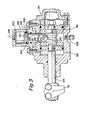
- the structure of the shift cylinder 124 and positioning and locking mechanism may be seen by reference to FIG. 3.
- the positioning and locking cylinder 148 is attached to, or formed integrally with, the shift cylinder 124.
- the shift cylinder 124 is mountable to the auxiliary transmission housing (not shown) as is well known in the art.
- Fluid connections 200 and 202 are provided in cylinder 124 for connection to passages 146 and 142, respectively.
- the piston 150 is provided with a drag ring 154 as discussed above.
- a ram 151 is fixed to, or integral with, the piston 150 for axial movement therewith and is provided with ramps 204 and 206 on the leading end thereof which are complementary with ramps 208 and 212, respectively, on the block 152.
- the ramps are sufficient, when pressurized air is vented from lines 118 and 120, and line 146 is pressurized, to center the block 152, and shift fork 72, in a neutral position.
- Ramps 210 and 214 may be provided for clearance purposes.
- the ram 151 has nontapered sides, 216 and 218, which are engageable by flat surfaces, 220 and 222, respectively, on the shift piston 122 to lock the shift piston 122 and shift fork 72 in the centered position.
- a vent and/or breather plug 224 may be provided in the shift cylinder 124.
- the positioning and locking piston when forced downwardly as shown in FIG. 3 by pressurization of line 146, is effective to position and lock the shift fork 72 in a neutral position for the auxiliary transmission. It may also be seen that once the shift fork 72 is locked in the neutral position, the shift fork may not be subsequently shifted to an engaged position until the main transmission is shifted to, or allowed to remain in, neutral simultaneously with the selector valve 132 switched to the mobile ("M") position.
Landscapes
- Engineering & Computer Science (AREA)
- General Engineering & Computer Science (AREA)
- Mechanical Engineering (AREA)
- Gear-Shifting Mechanisms (AREA)
Claims (14)
Applications Claiming Priority (2)
| Application Number | Priority Date | Filing Date | Title |
|---|---|---|---|
| US06/208,962 US4388843A (en) | 1980-11-21 | 1980-11-21 | Auxiliary transmission neutral positioning and locking control and mechanism |
| US208962 | 1980-11-21 |
Publications (3)
| Publication Number | Publication Date |
|---|---|
| EP0052814A2 EP0052814A2 (de) | 1982-06-02 |
| EP0052814A3 EP0052814A3 (en) | 1983-04-27 |
| EP0052814B1 true EP0052814B1 (de) | 1986-04-09 |
Family
ID=22776767
Family Applications (1)
| Application Number | Title | Priority Date | Filing Date |
|---|---|---|---|
| EP81109445A Expired EP0052814B1 (de) | 1980-11-21 | 1981-10-30 | Steuerung und Mechanismus zum Verbringen eines Hilfsgetriebes in die Leerlaufstellung und zum Verriegeln in derselben |
Country Status (4)
| Country | Link |
|---|---|
| US (1) | US4388843A (de) |
| EP (1) | EP0052814B1 (de) |
| AR (1) | AR227445A1 (de) |
| DE (1) | DE3174340D1 (de) |
Cited By (1)
| Publication number | Priority date | Publication date | Assignee | Title |
|---|---|---|---|---|
| US6575056B1 (en) | 1999-05-12 | 2003-06-10 | Zf Friedrichshaften Ag | Dual layshaft transmission |
Families Citing this family (36)
| Publication number | Priority date | Publication date | Assignee | Title |
|---|---|---|---|---|
| AU537361B2 (en) * | 1981-07-29 | 1984-06-21 | Kubota Ltd. | Transmission with multiple shafts and clutches |
| US4527447A (en) * | 1982-12-06 | 1985-07-09 | Eaton Corporation | Automatic mechanical transmission system |
| DE3312218A1 (de) * | 1983-04-05 | 1984-10-11 | Hudelmaier, geb. Otto, Ingrid, 7900 Ulm | Transportbetonmischer |
| DE3315221A1 (de) * | 1983-04-27 | 1984-10-31 | Wabco Westinghouse Fahrzeugbremsen GmbH, 3000 Hannover | Betaetigungseinrichtung zum schalten von gaengen und gassen eines fahrzeug-getriebes |
| US4555959A (en) * | 1983-05-09 | 1985-12-03 | Eaton Corporation | Shift control system |
| US4549443A (en) * | 1983-12-07 | 1985-10-29 | Twin Disc, Incorporated | Multi-speed reversible transmission of countershaft construction |
| DE3429531A1 (de) * | 1984-08-10 | 1986-02-20 | Wabco Westinghouse Fahrzeugbremsen GmbH, 3000 Hannover | Hilfskraftbetaetigtes fahrzeuggetriebe |
| JPS61167756A (ja) * | 1985-01-19 | 1986-07-29 | Toyota Motor Corp | 変速機の制御装置 |
| JPH0663558B2 (ja) * | 1985-01-19 | 1994-08-22 | トヨタ自動車株式会社 | 変速機の制御装置 |
| JPH0810026B2 (ja) * | 1985-01-19 | 1996-01-31 | アイシン・エィ・ダブリュ 株式会社 | 変速機の制御装置 |
| JPS61167743A (ja) * | 1985-01-19 | 1986-07-29 | Toyota Motor Corp | 変速機 |
| US4615421A (en) * | 1985-03-21 | 1986-10-07 | Eaton Corporation | Electro-mechanical shifter for hydraulic transmission |
| US4754665A (en) * | 1986-02-05 | 1988-07-05 | Eaton Corporation | Auxiliary transmission section |
| DE3633372A1 (de) * | 1986-10-01 | 1988-04-14 | Deere & Co | Verfahren zum schalten eines aus mehreren getriebeeinheiten bestehenden getriebes |
| US4722237A (en) * | 1986-12-12 | 1988-02-02 | Eaton Corporation | Fluid actuated shift bar housing assembly having a centering cylinder therein |
| US4788889A (en) * | 1987-03-19 | 1988-12-06 | Eaton Corporation | Mechanical transmission and control method therefor |
| US4807493A (en) * | 1987-09-25 | 1989-02-28 | Dana Corporation | Twin countershaft transmission with floating main shaft |
| US4920813A (en) * | 1988-05-20 | 1990-05-01 | Dana Corporation | Power take-off control apparatus |
| US4974468A (en) * | 1989-02-16 | 1990-12-04 | Eaton Corporation | Compound transmission and shift control therefor |
| US4944197A (en) * | 1989-06-07 | 1990-07-31 | Eaton Corporation | Resilient range interlock |
| GB9008424D0 (en) * | 1990-04-12 | 1990-06-13 | Eaton Corp | Power take-off engagement mechanism |
| US5216931A (en) * | 1992-01-23 | 1993-06-08 | Eaton Corporation | Interlock mechanism for range section slave valve |
| US5231895A (en) * | 1992-01-23 | 1993-08-03 | Eaton Corporation | Auxiliary section actuator air control system |
| US5383374A (en) * | 1993-05-05 | 1995-01-24 | Eaton Corporation | Countershaft driven auxiliary drive unit |
| GB9312014D0 (en) * | 1993-06-10 | 1993-07-28 | Eaton Corp | Auxiliary transmission system and input splitter therefor |
| US5511437A (en) * | 1993-07-01 | 1996-04-30 | Eaton Corporation | Compound vehicular transmission |
| US5569115A (en) * | 1995-07-27 | 1996-10-29 | Rockwell International Corporation | Engine speed synchronization system for assisting in manual transmission shifting |
| US5582558A (en) * | 1995-07-27 | 1996-12-10 | Rockwell International Corporation | Combined system for assisting shifting of manual transmission |
| US5669852A (en) * | 1995-07-27 | 1997-09-23 | Rockwell International Corporation | Two-position neutral switch for multi-speed transmission |
| US6067871A (en) * | 1997-09-12 | 2000-05-30 | Eaton Corporation | Variable resistance shift rail detent assembly and shift control method employing same |
| US6073502A (en) * | 1998-03-20 | 2000-06-13 | Muncie Power Products, Inc. | Power takeoff device |
| US6092433A (en) * | 1998-06-09 | 2000-07-25 | Zf Meritor, L.L.C. | Small envelope range piston housing for electrical transmission range shift system |
| DE102007003340A1 (de) * | 2007-01-17 | 2008-07-24 | Deere & Company, Moline | Getriebe |
| CN105257257B (zh) * | 2015-11-04 | 2018-02-09 | 泰坤控股有限公司 | 一种节能且具有安全保护功能的抽油机减速装置 |
| US10029562B2 (en) | 2016-08-26 | 2018-07-24 | Deere & Company | Power take-off arrangement for work vehicle |
| US10150367B2 (en) | 2016-08-26 | 2018-12-11 | Deere & Company | PTO speed control system for work vehicle |
Family Cites Families (18)
| Publication number | Priority date | Publication date | Assignee | Title |
|---|---|---|---|---|
| US2438539A (en) * | 1945-04-19 | 1948-03-30 | Fuller Mfg Co | Combined auxiliary transmission and power take-off |
| CH251788A (de) * | 1946-09-16 | 1947-11-15 | Saurer Ag Adolph | Wechselgetriebe mit sperrsynchronisierten Schaltkupplungen. |
| US2958225A (en) * | 1954-08-10 | 1960-11-01 | Dana Corp | Power take-off having an interlock with fluid transmission |
| US2761322A (en) * | 1954-08-13 | 1956-09-04 | Gar Wood Ind Inc | Control for power take-off |
| US2798382A (en) * | 1955-04-04 | 1957-07-09 | Dana Corp | Power take-off control mechanism |
| US2899034A (en) * | 1956-10-29 | 1959-08-11 | Int Harvester Co | Independent power take-off mechanism |
| US3039320A (en) * | 1957-05-21 | 1962-06-19 | Zens Pierre Marie Felix | Device for changing speed in gear-boxes |
| US3171300A (en) * | 1961-07-11 | 1965-03-02 | Eaton Mfg Co | Control for a main and auxiliary transmission system |
| US3283613A (en) * | 1964-04-20 | 1966-11-08 | Eaton Yale & Towne | Automotive device |
| CH498317A (de) * | 1968-09-11 | 1970-10-31 | Saurer Ag Adolph | Vorgelegewechselgetriebe |
| FR2064641A5 (de) * | 1969-10-06 | 1971-07-23 | Ifa Getriebewerke | |
| US3799002A (en) * | 1972-07-31 | 1974-03-26 | Eaton Corp | Transmission with resiliently loaded main shaft gears |
| US3648546A (en) * | 1970-09-30 | 1972-03-14 | Eaton Yale & Towne | Transmission having low-inertia mainshaft |
| IT959062B (it) * | 1972-06-06 | 1973-11-10 | Fiat Spa | Dispositivo per la selezione auto matica della velocita di rotazione dell albero di presa di forza di trattori agricoli in funzione del tipo di codulo scanalato di estre mita applicato all albero |
| SE371611B (de) * | 1972-11-17 | 1974-11-25 | Volvo Ab | |
| AT349909B (de) * | 1977-10-05 | 1979-05-10 | Steyr Daimler Puch Ag | Schalteinrichtung fuer ein kraftfahrzeug- wechselgetriebe |
| SE421057B (sv) * | 1978-04-24 | 1981-11-23 | Volvo Ab | Anordning for att forhindra felvexling |
| US4192196A (en) * | 1978-07-31 | 1980-03-11 | Eaton Corporation | Blocked change gear transmission and improved blocker and jaw clutch assembly therefor |
-
1980
- 1980-11-21 US US06/208,962 patent/US4388843A/en not_active Expired - Lifetime
-
1981
- 1981-10-30 EP EP81109445A patent/EP0052814B1/de not_active Expired
- 1981-10-30 DE DE8181109445T patent/DE3174340D1/de not_active Expired
- 1981-11-11 AR AR287412A patent/AR227445A1/es active
Cited By (1)
| Publication number | Priority date | Publication date | Assignee | Title |
|---|---|---|---|---|
| US6575056B1 (en) | 1999-05-12 | 2003-06-10 | Zf Friedrichshaften Ag | Dual layshaft transmission |
Also Published As
| Publication number | Publication date |
|---|---|
| US4388843A (en) | 1983-06-21 |
| AR227445A1 (es) | 1982-10-29 |
| EP0052814A3 (en) | 1983-04-27 |
| DE3174340D1 (en) | 1986-05-15 |
| EP0052814A2 (de) | 1982-06-02 |
Similar Documents
| Publication | Publication Date | Title |
|---|---|---|
| EP0052814B1 (de) | Steuerung und Mechanismus zum Verbringen eines Hilfsgetriebes in die Leerlaufstellung und zum Verriegeln in derselben | |
| US4974474A (en) | Pneumatic control system for range type compound transmission | |
| EP0552871B1 (de) | Aufbau eines Schutzventiles für ein Bereichsgetriebe | |
| CA2085043C (en) | Automatic range shift arrangement | |
| EP0127949B1 (de) | Getriebe-Schaltsystem | |
| EP0614030B1 (de) | Schaltzylinder für drei Schaltstellungen | |
| US5216931A (en) | Interlock mechanism for range section slave valve | |
| US5199314A (en) | Synchronized splitter section protection system/method | |
| US4788875A (en) | Auxiliary transmission section shift control system | |
| US5224392A (en) | Variable pressure range section actuator piston | |
| US5199312A (en) | Range section actuator control system and method for preventing damage to range section synchronizers | |
| EP0552867B1 (de) | Zweistufige Zylinder/Kolben-Anordnung | |
| EP0927838B1 (de) | Druckgesteuertes Umschaltventil für ein Stufengetriebe | |
| EP0552572B1 (de) | Anordnung eines Getriebeschaltgliedes mit zwei Drücken | |
| EP0552901B1 (de) | Pneumatische Steuerung mit Vorab-Entlüftung für ein Zusatzgetriebe | |
| EP0552868B1 (de) | Anordnung eines Getriebebereich-Schaltgliedes mit variablem Druck | |
| US5907974A (en) | Splitter lockout system arranged for conversion between first and second owner configurations | |
| EP0552870B1 (de) | Steuerungseinrichtung und -verfahren für eine Zusatzgetriebebetätigung |
Legal Events
| Date | Code | Title | Description |
|---|---|---|---|
| PUAI | Public reference made under article 153(3) epc to a published international application that has entered the european phase |
Free format text: ORIGINAL CODE: 0009012 |
|
| AK | Designated contracting states |
Designated state(s): DE FR GB IT |
|
| PUAL | Search report despatched |
Free format text: ORIGINAL CODE: 0009013 |
|
| AK | Designated contracting states |
Designated state(s): DE FR GB IT |
|
| 17P | Request for examination filed |
Effective date: 19830825 |
|
| GRAA | (expected) grant |
Free format text: ORIGINAL CODE: 0009210 |
|
| AK | Designated contracting states |
Kind code of ref document: B1 Designated state(s): DE FR GB IT |
|
| ITF | It: translation for a ep patent filed | ||
| REF | Corresponds to: |
Ref document number: 3174340 Country of ref document: DE Date of ref document: 19860515 |
|
| ET | Fr: translation filed | ||
| PLBE | No opposition filed within time limit |
Free format text: ORIGINAL CODE: 0009261 |
|
| STAA | Information on the status of an ep patent application or granted ep patent |
Free format text: STATUS: NO OPPOSITION FILED WITHIN TIME LIMIT |
|
| 26N | No opposition filed | ||
| ITTA | It: last paid annual fee | ||
| PGFP | Annual fee paid to national office [announced via postgrant information from national office to epo] |
Ref country code: GB Payment date: 19940927 Year of fee payment: 14 |
|
| PGFP | Annual fee paid to national office [announced via postgrant information from national office to epo] |
Ref country code: FR Payment date: 19941012 Year of fee payment: 14 |
|
| PGFP | Annual fee paid to national office [announced via postgrant information from national office to epo] |
Ref country code: DE Payment date: 19941027 Year of fee payment: 14 |
|
| PG25 | Lapsed in a contracting state [announced via postgrant information from national office to epo] |
Ref country code: GB Effective date: 19951030 |
|
| GBPC | Gb: european patent ceased through non-payment of renewal fee |
Effective date: 19951030 |
|
| PG25 | Lapsed in a contracting state [announced via postgrant information from national office to epo] |
Ref country code: FR Effective date: 19960628 |
|
| PG25 | Lapsed in a contracting state [announced via postgrant information from national office to epo] |
Ref country code: DE Effective date: 19960702 |
|
| REG | Reference to a national code |
Ref country code: FR Ref legal event code: ST |