US4899607A - Electrically controlled pressurized fluid actuated X-Y shifting mechanism - Google Patents
Electrically controlled pressurized fluid actuated X-Y shifting mechanism Download PDFInfo
- Publication number
- US4899607A US4899607A US07/261,454 US26145488A US4899607A US 4899607 A US4899607 A US 4899607A US 26145488 A US26145488 A US 26145488A US 4899607 A US4899607 A US 4899607A
- Authority
- US
- United States
- Prior art keywords
- shift
- shaft
- housing
- shifting mechanism
- valves
- Prior art date
- Legal status (The legal status is an assumption and is not a legal conclusion. Google has not performed a legal analysis and makes no representation as to the accuracy of the status listed.)
- Expired - Fee Related
Links
- 230000007246 mechanism Effects 0.000 title claims abstract description 51
- 239000012530 fluid Substances 0.000 title claims abstract description 28
- 230000005540 biological transmission Effects 0.000 claims abstract description 17
- 230000008859 change Effects 0.000 claims abstract description 7
- 230000000903 blocking effect Effects 0.000 claims 2
- 230000000712 assembly Effects 0.000 abstract description 7
- 238000000429 assembly Methods 0.000 abstract description 7
- 230000007935 neutral effect Effects 0.000 description 12
- 230000009347 mechanical transmission Effects 0.000 description 10
- 238000006073 displacement reaction Methods 0.000 description 6
- 230000004048 modification Effects 0.000 description 2
- 238000012986 modification Methods 0.000 description 2
- 230000009471 action Effects 0.000 description 1
- 230000001276 controlling effect Effects 0.000 description 1
- 230000000694 effects Effects 0.000 description 1
- 230000008676 import Effects 0.000 description 1
- 230000003993 interaction Effects 0.000 description 1
- 238000004519 manufacturing process Methods 0.000 description 1
- 230000008707 rearrangement Effects 0.000 description 1
- 230000001105 regulatory effect Effects 0.000 description 1
- 230000008439 repair process Effects 0.000 description 1
- 230000000717 retained effect Effects 0.000 description 1
- 238000006467 substitution reaction Methods 0.000 description 1
Images
Classifications
-
- F—MECHANICAL ENGINEERING; LIGHTING; HEATING; WEAPONS; BLASTING
- F16—ENGINEERING ELEMENTS AND UNITS; GENERAL MEASURES FOR PRODUCING AND MAINTAINING EFFECTIVE FUNCTIONING OF MACHINES OR INSTALLATIONS; THERMAL INSULATION IN GENERAL
- F16H—GEARING
- F16H61/00—Control functions within control units of change-speed- or reversing-gearings for conveying rotary motion ; Control of exclusively fluid gearing, friction gearing, gearings with endless flexible members or other particular types of gearing
- F16H61/26—Generation or transmission of movements for final actuating mechanisms
- F16H61/28—Generation or transmission of movements for final actuating mechanisms with at least one movement of the final actuating mechanism being caused by a non-mechanical force, e.g. power-assisted
- F16H61/2807—Generation or transmission of movements for final actuating mechanisms with at least one movement of the final actuating mechanism being caused by a non-mechanical force, e.g. power-assisted using electric control signals for shift actuators, e.g. electro-hydraulic control therefor
-
- F—MECHANICAL ENGINEERING; LIGHTING; HEATING; WEAPONS; BLASTING
- F16—ENGINEERING ELEMENTS AND UNITS; GENERAL MEASURES FOR PRODUCING AND MAINTAINING EFFECTIVE FUNCTIONING OF MACHINES OR INSTALLATIONS; THERMAL INSULATION IN GENERAL
- F16H—GEARING
- F16H61/00—Control functions within control units of change-speed- or reversing-gearings for conveying rotary motion ; Control of exclusively fluid gearing, friction gearing, gearings with endless flexible members or other particular types of gearing
- F16H61/26—Generation or transmission of movements for final actuating mechanisms
- F16H61/28—Generation or transmission of movements for final actuating mechanisms with at least one movement of the final actuating mechanism being caused by a non-mechanical force, e.g. power-assisted
- F16H61/30—Hydraulic or pneumatic motors or related fluid control means therefor
- F16H2061/307—Actuators with three or more defined positions, e.g. three position servos
-
- F—MECHANICAL ENGINEERING; LIGHTING; HEATING; WEAPONS; BLASTING
- F16—ENGINEERING ELEMENTS AND UNITS; GENERAL MEASURES FOR PRODUCING AND MAINTAINING EFFECTIVE FUNCTIONING OF MACHINES OR INSTALLATIONS; THERMAL INSULATION IN GENERAL
- F16H—GEARING
- F16H61/00—Control functions within control units of change-speed- or reversing-gearings for conveying rotary motion ; Control of exclusively fluid gearing, friction gearing, gearings with endless flexible members or other particular types of gearing
- F16H61/26—Generation or transmission of movements for final actuating mechanisms
- F16H61/28—Generation or transmission of movements for final actuating mechanisms with at least one movement of the final actuating mechanism being caused by a non-mechanical force, e.g. power-assisted
- F16H61/30—Hydraulic or pneumatic motors or related fluid control means therefor
- F16H2061/308—Modular hydraulic shift units, i.e. preassembled actuator units for select and shift movements adapted for being mounted on transmission casing
-
- Y—GENERAL TAGGING OF NEW TECHNOLOGICAL DEVELOPMENTS; GENERAL TAGGING OF CROSS-SECTIONAL TECHNOLOGIES SPANNING OVER SEVERAL SECTIONS OF THE IPC; TECHNICAL SUBJECTS COVERED BY FORMER USPC CROSS-REFERENCE ART COLLECTIONS [XRACs] AND DIGESTS
- Y10—TECHNICAL SUBJECTS COVERED BY FORMER USPC
- Y10T—TECHNICAL SUBJECTS COVERED BY FORMER US CLASSIFICATION
- Y10T74/00—Machine element or mechanism
- Y10T74/19—Gearing
- Y10T74/19219—Interchangeably locked
- Y10T74/19251—Control mechanism
-
- Y—GENERAL TAGGING OF NEW TECHNOLOGICAL DEVELOPMENTS; GENERAL TAGGING OF CROSS-SECTIONAL TECHNOLOGIES SPANNING OVER SEVERAL SECTIONS OF THE IPC; TECHNICAL SUBJECTS COVERED BY FORMER USPC CROSS-REFERENCE ART COLLECTIONS [XRACs] AND DIGESTS
- Y10—TECHNICAL SUBJECTS COVERED BY FORMER USPC
- Y10T—TECHNICAL SUBJECTS COVERED BY FORMER US CLASSIFICATION
- Y10T74/00—Machine element or mechanism
- Y10T74/19—Gearing
- Y10T74/19219—Interchangeably locked
- Y10T74/19377—Slidable keys or clutches
- Y10T74/19414—Single clutch shaft
- Y10T74/19419—Progressive
- Y10T74/19423—Multiple key
- Y10T74/19428—Spur
- Y10T74/19433—Fluid operated
-
- Y—GENERAL TAGGING OF NEW TECHNOLOGICAL DEVELOPMENTS; GENERAL TAGGING OF CROSS-SECTIONAL TECHNOLOGIES SPANNING OVER SEVERAL SECTIONS OF THE IPC; TECHNICAL SUBJECTS COVERED BY FORMER USPC CROSS-REFERENCE ART COLLECTIONS [XRACs] AND DIGESTS
- Y10—TECHNICAL SUBJECTS COVERED BY FORMER USPC
- Y10T—TECHNICAL SUBJECTS COVERED BY FORMER US CLASSIFICATION
- Y10T74/00—Machine element or mechanism
- Y10T74/19—Gearing
- Y10T74/19219—Interchangeably locked
- Y10T74/19377—Slidable keys or clutches
- Y10T74/19414—Single clutch shaft
- Y10T74/19419—Progressive
- Y10T74/19423—Multiple key
- Y10T74/19428—Spur
- Y10T74/19437—Electrically operated
-
- Y—GENERAL TAGGING OF NEW TECHNOLOGICAL DEVELOPMENTS; GENERAL TAGGING OF CROSS-SECTIONAL TECHNOLOGIES SPANNING OVER SEVERAL SECTIONS OF THE IPC; TECHNICAL SUBJECTS COVERED BY FORMER USPC CROSS-REFERENCE ART COLLECTIONS [XRACs] AND DIGESTS
- Y10—TECHNICAL SUBJECTS COVERED BY FORMER USPC
- Y10T—TECHNICAL SUBJECTS COVERED BY FORMER US CLASSIFICATION
- Y10T74/00—Machine element or mechanism
- Y10T74/20—Control lever and linkage systems
- Y10T74/20012—Multiple controlled elements
- Y10T74/20018—Transmission control
- Y10T74/20024—Fluid actuator
-
- Y—GENERAL TAGGING OF NEW TECHNOLOGICAL DEVELOPMENTS; GENERAL TAGGING OF CROSS-SECTIONAL TECHNOLOGIES SPANNING OVER SEVERAL SECTIONS OF THE IPC; TECHNICAL SUBJECTS COVERED BY FORMER USPC CROSS-REFERENCE ART COLLECTIONS [XRACs] AND DIGESTS
- Y10—TECHNICAL SUBJECTS COVERED BY FORMER USPC
- Y10T—TECHNICAL SUBJECTS COVERED BY FORMER US CLASSIFICATION
- Y10T74/00—Machine element or mechanism
- Y10T74/20—Control lever and linkage systems
- Y10T74/20012—Multiple controlled elements
- Y10T74/20018—Transmission control
- Y10T74/2003—Electrical actuator
Definitions
- the present invention relates to a shifting mechanism of the "X-Y type" for cooperation with a shift bar housing assembly for selectively shifting a change gear mechanical transmission.
- the present invention relates to an electrically controlled, pressurized fluid actuated X-Y shifting mechanism which is effective to cooperate with a substantially standard shift bar housing assembly of the type normally manually controlled by a shift lever allowing for the automatic or semi-automatic shifting operation of an otherwise substantially standard normally manually shifted mechanical transmission.
- Shift bar housing assemblies for mechanical change gear transmissions comprising a plurality of generally parallel, independently axially movable shift bars or shift rails, each carrying a shift fork fixed thereto, and shift block mechanisms allowing a single shift bar to be selected and axially moved to effect engagement/disengagement of a particular gear ratio are well known in the prior art as may be seen by reference to U.S. Pat. Nos. 2,951,392; 4,455,883; 4,515,029; 4,567,785 and 4,584,895, the disclosures of all of which are hereby incorporated by reference.
- shift bar housings are manually controlled and operated by a shift finger fixed to a directly mounted shift lever or to the cross shaft of a remotely controlled shifting mechanism.
- Interlock mechanisms are usually provided to prevent movement of more than one shift rail at a time from the axially centered or neutral positions thereof.
- Shift bar housing assemblies utilizing pressurized fluid actuated pistons and the like to control each shift rail in an automatic or semi-automatic mechanical transmission are known in the prior art as may be seen by reference to U.S. Pat. No. 4,445,393.
- the drawbacks of the prior art have been minimized or overcome by the provision of a relatively simple and reliable X-Y shifting mechanism which is easily connectable to electric and pressurized fluid sources and is compatible with the shift bar housing assemblies of normally manually shifted mechanical transmissions with little or no modifications thereto.
- the X-Y shifting mechanism of the present invention provides a rapidly and positively obtainable neutral position and includes a sensor to verify obtaining of neutral. Additionally, maintaining in gear and neutral positioning does not rely upon maintaining differential pressures, accordingly the transmission will retain its current in gear or neutral position in the event of an electric or pressurized fluid power failure.
- the X-Y shift mechanism is preferably electrically controlled and pressurized fluid, preferably pressurized air from a vehicular onboard air system, actuated and requires only a single electric and a single pressurized fluid connection thereto.
- the single pressurized fluid connection connects to a common gallery which is connected to six three-way two-position valves, such a solenoid controlled valves, which supply fluid to, or exhaust fluid from, two transversely oriented three-position piston/cylinder assemblies.
- One of the pistons moves or pivots the shift finger in the X direction to align the shift finger with a selected shift rail while the other piston moves the shift finger in the Y direction for desired axial movement of the selected shift rail.
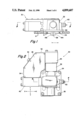
- FIG. 1 is a front view of the X-Y shifting mechanism of the present invention.
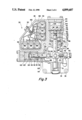
- FIG. 2 is a top view of the X-Y shifting mechanism of the present invention.
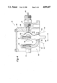
- FIG. 3 is a sectional view of the X-Y shifting mechanism of the present invention taken substantially along line 3--3 in FIG. 1.
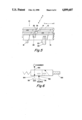
- FIG. 4 is a partial sectional view of the X-Y shifting mechanism of the present invention taken substantially along line 4--4 in FIG. 2.
- FIG. 5 is a schematic illustration of a portion of mechanical transmission shift bar housing assembly of the type suited for control with the X-Y shifting mechanism of the present invention.
- FIG. 6 is a schematic illustration of three-way two-position electrically controlled valves advantageously utilized in the X-Y shifting mechanism of the present invention.
- Change gear heavy duty truck mechanical transmissions are well known in the prior art as may be seen by reference to U.S. Pat. No. 3,105,395 hereby incorporated by reference.
- First class lever mechanisms for directly shifting such change gear transmissions are well known in the art as may be seen by reference to U.S. Pat. Nos. 3,934,485 and 4,022,077, hereby both incorporated by reference.
- Remote controls for shifting transmissions of this type are also well known in the art as may be seen by reference to U.S. Pat. Nos. 2,040,549; 4,104,929 or 4,157,740 and 4,206,826, all hereby incorporated by reference.
- Such transmissions typically included a shift bar housing assembly an example of which may be seen schematically in FIG. 5.
- the shift bar housing assembly 10 typically comprises a plurality of axially movable shift rails, 12, 14 and 16, each of which carry a shift fork 18, 20 and 22, respectively, fixed thereto for axial movement therewith.
- the shift forks are each associated with a positive clutch mechanism for selectively engaging/disengaging a first and/or a second gear to a shaft.
- shifting of such transmissions is accomplished by selecting a shift rail by moving an engagement member such as a shift finger axially or pivotably along the axis X--X into alignment with a shift block or notch 24, 26 or 28 carried by the selected shift rail and then causing axial movement of the selected shift rail by axially moving or pivoting the shift finger to apply an axial force in the direction of axis Y--Y.
- an engagement member such as a shift finger axially or pivotably along the axis X--X into alignment with a shift block or notch 24, 26 or 28 carried by the selected shift rail and then causing axial movement of the selected shift rail by axially moving or pivoting the shift finger to apply an axial force in the direction of axis Y--Y.
- a first class lever which could be pivoted in the directions of axes X--X and Y--Y or by utilization of a shift shaft carrying a shift finger thereon which was axially movable in the direction of axis X--X and then pivotably movable about the axis X--X to apply an axial force in the direction of the axis Y--Y.
- a shifting mechanism in the prior art typically a first class lever, was utilized to align with and then apply an axial force to the shift block or slot member carried by a selected shift rail while in the case of remotely shifted transmission a torque arm having one end thereof fixed for rotation and axial movement with the shift shaft was typically utilized to apply a selective axial and rotational movement to a shift finger carried for movement with the shift shaft.
- shift bar housing assembly 10 illustrated in FIG. 5 and normally controlled by a manual shift lever or the like that the X-Y shifter 30 of the present invention is advantageous utilized to provide automatic or semi-automatic operation of a mechanical transmission.
- X-Y shifting mechanism 30 is enclosed within a housing 32 having a mounting plate portion 34 with bolt bores 36 in a pattern allowing the mechanism 30 to be mounted at the upper opening A in a transmission shift bar housing H normally receiving the shift tower.
- a shift finger 38 extends downwardly from housing 32 for interaction with the shift rails.
- Housing 32 includes a portion 40 enclosing the select piston/cylinder assembly 42 for moving shift finger, axially or pivotably, in the direction of line X--X for selection of a selected shift rail, 12, 14 or 16; and a transversely extending portion 44 enclosing piston/cylinder assembly 46 for moving shift finger 38 in the direction of line Y--Y to cause axial movement of the selected shift rail and its associated shift fork for engaging or disengaging a selected transmission ratio gear.
- piston/cylinder assembly 46 is larger than piston/cylinder assembly 42 as moving shift finger 38 in the engagement, i.e. Y--Y, direction requires greater force than moving shift finger 38 in the selection, i.e. X--X, direction.
- Housing 32 also includes a valving portion 48 defining a single multiple pin electric connector 50, a single inlet 52 for connection to a source of pressurized fluid, such as a regulated, dried, filtered connection to the onboard vehicle air system, and a pressurized fluid exhaust to atmosphere 54.
- the valving portion 48 also contains the valves for controlling the X--X and Y--Y piston/cylinder assemblies, 42 and 46, respectively, a common pressurized fluid gallery 56 fluidly connected to inlet 52 and a common exhaust gallery 58 fluidly connected to the exhaust outlet 54.
- Housing 32 also defines a connector 60 for a neutral position sensor 62 and a pair of breather plugs 64 and 66 for the piston/cylinder assemblies. Other vent or breather plugs may be provided as necessary.
- the engagement/disengagement assembly 46 for moving shift finger 38 in the Y--Y axial direction comprises a shaft 68 supported as at sleeve bushings 70 for axial movement in the Y--Y direction, and pivotal movement, relative to housing 32.
- the shift finger 38 is integral with a shift finger carrier 72 axially and rotationally fixed to shaft 68 as by set screw 74.
- a piston 76 Adjacent its upper end, a piston 76 is axially fixed to shaft 68 between a shoulder 78 and a nut and washer 80 retained on threaded upper extension 82 of shaft 68. Piston 76 is slidably and sealingly received within cylinder member 84 to define sealed chambers 86 and 88. A piston 90 is slidably and sealingly received within a cylinder member 92. The piston 90 and cylinder 92 define a sealed chamber 94 above the piston. Downward axial movement of piston 90 is limited by washer shaped stop member 96 having a central opening 98 allowing the lower surface 100 of piston 90 to fluidly communicate with and define chamber 88 and to contact extension 82 of shaft 68.
- Piston 76 defines an upper and a lower surface 102 and 104, exposed to a pressure in chambers 88 and 86, respectively, which are smaller than the upper surface 106 and lower surface 100 of piston 90 exposed to fluid pressure in chambers 94 and 88, respectively. While surface 106 is equal in area to surface 100, at times when piston surface 100 is engaging stop member 96 or extension 82, the effective area of surface 106 exceeds that of surface 100.
- the piston/cylinder assembly 46 allows shaft 68 to assume any selected one of three selectable axial positions, namely axially centered as illustrated in FIG. 3, an upward axial displacement wherein surface 102 will contact stop member 96 and a downward axial displacement wherein surface 104 contacts a stop member 108.
- the upward and downward displacements are selected in view of the required axial displacements of shift rails and associated shift forks to cause engagement and disengagement of transmission ratio gears.
- chambers 94 and 86 are pressurized while chamber 88 is exhausted.
- chambers 88 and 94 are pressurized while chamber 86 is exhausted. It is noted that chamber 94 could be exhausted to achieve the same but somewhat slower downward displacement.
- chamber 86 is pressurized while chambers 88 and 94 are exhausted.
- Movement of shift finger 38 in the X--X direction to align the shift finger with a selected shift rail is accomplished by selective axial positioning of shaft 110 which is slidably supported in housing 32 as by bushing 112 for movement substantially perpendicular to the axial movement of shaft 68. Except for being somewhat smaller in size, shaft 110 and its associated piston/cylinder assembly 42 is substantially functionally and structurally identical to that of shaft 68 and associated piston/cylinder assembly 46 described above.
- piston 114 is fixed to shaft 10 and defines sealed chambers 116 on 118 on the right and left faces, respectively, thereof.
- a larger piston for contact with a leftwardly extending extension of shaft 110 has a rightwardly facing surface exposed to pressure in chamber 118 and a leftwardly facing surface defining and exposed to fluid pressure in a sealed chamber 122.
- a first washer shaped stop member 124 limits rightward axial movement of piston 120 and leftward axial movement of piston 114. Stop member 126 limits rightward axial movement of piston 114.
- a crank mechanism 130 for pivoting shift finger in the X--X direction is controlled by shaft 110.
- a crank connector 132 is attached to shaft 110 as by set screw 134.
- the crank connector 132 includes a portion 136 axially offset but substantially parallel to shaft 110.
- Portion 136 defines a slot 138 for receipt of a generally bulbulous portion 140 defined by the shift finger carrier to define a ball and slotted socket type connection.
- the carrier 72 and shift finger 38 are thus a crank lever, pivotably movable about the axis 142 of shaft 68.
- shift finger 38 will align with the shift block 26 of shift rail 14. Movement of shaft 110 rightwardly will cause shift finger 38 to pivot to the position illustrated by phantom line 144 for alignment with shift block 28 of shift rail 16. Movement of shaft 110 leftwardly will cause the shift finger 38 to pivot to the position illustrated by phantom line 146 to align with shift block 24 of shift rail 12.
- Pressurization of chambers 122 and 116 and exhaust of chamber 118 will cause shaft 110 to assume the axially centered position of FIG. 3. Pressurization of chamber 118, and preferably chamber 122, and exhaust of chamber 116 will cause shaft 110 to be axially displaced rightwardly. Pressurization of chamber 116 and exhaust of chambers 118 and 122 will cause shaft 110 to be displaced axially leftwardly.
- the valves are of a standard type having a first port 162 connected to a common gallery 56 of pressurized fluid supplied by single-inlet connection 52, a second port 164 connected to common exhaust gallery 58 and a third port 166 connected to the individual chamber controlled by the valve.
- the valve is normally in the chamber exhaust position and, by action of the solenoid 160, is movable to the chamber pressurization position. Control of the various operating solenoids for the valves 150, 152, 154, 156, 158 and 160 is by the single electrical connector 50.
- a spring biased detent plunger 170 cooperates with a detent groove 172 to resiliently bias the finger 38 in the neutral condition and cooperates with sensor 62 to provide a neutral signal to the transmission control unit.
- shaft 68 and thus shift finger 38, once positioned in a selective axial position will remain in that position even if all pressure to the various chambers is removed. Accordingly, especially if the shaft rails are provided with standard ingear and neutral detent devices, in the event of a pressure fluid failure, the X-Y shifter 30 will allow the engaged gear to remain engaged.
Landscapes
- Engineering & Computer Science (AREA)
- General Engineering & Computer Science (AREA)
- Mechanical Engineering (AREA)
- Gear-Shifting Mechanisms (AREA)
- Arrangement Or Mounting Of Control Devices For Change-Speed Gearing (AREA)
Applications Claiming Priority (2)
| Application Number | Priority Date | Filing Date | Title |
|---|---|---|---|
| GB878725981A GB8725981D0 (en) | 1987-11-05 | 1987-11-05 | X-y shifting mechanism |
| GB8725981 | 1987-11-05 |
Publications (1)
| Publication Number | Publication Date |
|---|---|
| US4899607A true US4899607A (en) | 1990-02-13 |
Family
ID=10626512
Family Applications (1)
| Application Number | Title | Priority Date | Filing Date |
|---|---|---|---|
| US07/261,454 Expired - Fee Related US4899607A (en) | 1987-11-05 | 1988-10-24 | Electrically controlled pressurized fluid actuated X-Y shifting mechanism |
Country Status (8)
| Country | Link |
|---|---|
| US (1) | US4899607A (de) |
| EP (1) | EP0315347B1 (de) |
| JP (1) | JPH01153849A (de) |
| AU (1) | AU611362B2 (de) |
| BR (1) | BR8805679A (de) |
| DE (1) | DE3883917T2 (de) |
| ES (1) | ES2058307T3 (de) |
| GB (1) | GB8725981D0 (de) |
Cited By (56)
| Publication number | Priority date | Publication date | Assignee | Title |
|---|---|---|---|---|
| US5031472A (en) * | 1989-02-11 | 1991-07-16 | Eaton Corporation | Neutral sensing assembly |
| US5094126A (en) * | 1989-01-25 | 1992-03-10 | Eaton Corporation | Transmission with a detachable emergency ratio selector |
| US5099711A (en) * | 1991-05-09 | 1992-03-31 | Eaton Corporation | Tooth butt/buzz control method/system |
| US5109721A (en) * | 1991-05-09 | 1992-05-05 | Eaton Corporation | Range shifting only fault tolerance method/system |
| US5109729A (en) * | 1991-05-09 | 1992-05-05 | Eaton Corporation | Throttle control fault detection and tolerance method/system |
| US5121649A (en) * | 1990-03-30 | 1992-06-16 | Valeo | Motorized gear shift control apparatus for a transmission gearbox, in particular for automotive vehicles |
| US5136897A (en) * | 1991-05-09 | 1992-08-11 | Eaton Corporation | Smooth upshift control method/system |
| US5138905A (en) * | 1990-08-31 | 1992-08-18 | Isuzu Motors, Ltd. | Electronic-controlled transmission |
| US5191804A (en) * | 1992-07-23 | 1993-03-09 | Eaton Corporation | Dual force fluid actuated shift device |
| US5274553A (en) * | 1991-05-09 | 1993-12-28 | Eaton Corporation | Torque converter slip rate based skip power downshift control strategy |
| US5279172A (en) * | 1992-10-22 | 1994-01-18 | Eaton Corporation | Four position fluid-actuated piston arrangement |
| US5305240A (en) * | 1992-11-25 | 1994-04-19 | Eaton Corporation | Computer controlled method of calibrating an x-y shifter |
| US5305213A (en) * | 1991-05-09 | 1994-04-19 | Eaton Corporation | Driveline torque limit control strategy-using SAE J1922 type engine control |
| US5389053A (en) * | 1993-07-21 | 1995-02-14 | Eaton Corporation | System and method for sliding clutch engagement under tooth butt or torque lock conditions |
| US5408898A (en) * | 1993-11-10 | 1995-04-25 | Eaton Corporation | Preselect shift strategy using stored energy |
| US5413012A (en) * | 1993-09-07 | 1995-05-09 | Eaton Corporation | Variable synchronous window |
| US5417124A (en) * | 1991-11-08 | 1995-05-23 | Iveco Fiat S.P.A. | Gear change for an industrial vehicle provided with an integrated control unit |
| US5425284A (en) * | 1993-09-07 | 1995-06-20 | Eaton Corporation | Automated mechanical transmission control system/method |
| EP0688977A2 (de) | 1994-06-25 | 1995-12-27 | Eaton Corporation | Behelfssteuerung für Getriebe bei Schaltfehlern |
| EP0688978A2 (de) | 1994-06-25 | 1995-12-27 | Eaton Corporation | Schaltzustandsüberwachung für ein Teilgetriebe |
| EP0695891A2 (de) | 1994-08-05 | 1996-02-07 | Eaton Corporation | System und Verfahren zur Auswahl des Anfahrgetriebeganges |
| EP0695893A2 (de) | 1994-08-06 | 1996-02-07 | Eaton Corporation | Steuerung für mechanisches, semi-automatisches Getriebe mit kontinuierlicher Auswahl |
| EP0697302A2 (de) | 1994-08-19 | 1996-02-21 | Eaton Corporation | Zurückschaltlogik für ein halbautomatisches mechanisches Getriebe mit manueller Kupplungsbetätigung |
| EP0702170A2 (de) | 1994-09-19 | 1996-03-20 | Eaton Corporation | Wiedereinkupplungssteuerung |
| US5528949A (en) * | 1993-03-03 | 1996-06-25 | Eaton Corporation | Three-position shift actuator |
| US5566070A (en) * | 1995-02-02 | 1996-10-15 | Eaton Corporation | Transmission shift control including deflection-type neutral signal error detection and response |
| US5623852A (en) * | 1993-04-10 | 1997-04-29 | Hydraulik-Ring Antriebs- Und Steuerungstechnik Gmbh | Adjusting drive system for transmission of motorized vehicles |
| EP0778429A2 (de) | 1995-12-07 | 1997-06-11 | Eaton Corporation | Steuerung für automatisiertes, mechanisches Getriebe |
| EP0784171A2 (de) | 1996-01-12 | 1997-07-16 | Eaton Corporation | Verfahren zur Auswahl eines bevorzugten Ganges beim Hoch- oder Rückschalten in einem Automatikgetriebe |
| US5661998A (en) * | 1996-02-06 | 1997-09-02 | Eaton Corporation | Three-position actuator piston assembly and actuator system utilizing same |
| US5743143A (en) * | 1996-08-09 | 1998-04-28 | Eaton Corporation | Transmission shifting mechanism and position sensor |
| US5878622A (en) * | 1996-02-23 | 1999-03-09 | Hydraulik--Ring Antriebs- und Steuerungstechnik GmbH | Actuating device for automatically operating manual transmissions of vehicles |
| EP0911207A2 (de) | 1997-10-16 | 1999-04-28 | Eaton Corporation | Gangschaltsteuerung und Verfahren für optimale Motorbremsung |
| US5941137A (en) * | 1995-08-11 | 1999-08-24 | Siemens Aktiengesellschaft | Controller for a motor vehicle with an automatic transmission |
| EP0947371A2 (de) | 1998-04-01 | 1999-10-06 | Eaton Corporation | Adaptive Schaltkraftsteuerung eines Stellglieds für ein Splittergetriebe |
| EP0947737A2 (de) | 1998-04-01 | 1999-10-06 | Eaton Corporation | Adaptive Leerlauferfassung |
| EP0947740A2 (de) | 1998-04-01 | 1999-10-06 | Eaton Corporation | Dynamische Betätigung einer Bereichsschaltanordnung |
| EP0947739A2 (de) | 1998-04-01 | 1999-10-06 | Eaton Corporation | Steuerung einer Bereichsschaltanordnung |
| EP0947744A2 (de) | 1998-04-01 | 1999-10-06 | Eaton Corporation | Klauenkupplung-Eingriffskontrolle für ein servounterstütztes, manuell geschaltetes Splitter-Getriebe |
| EP0947741A2 (de) | 1998-04-01 | 1999-10-06 | Eaton Corporation | Adaptive Klauenkupplung-Eingriffskontrolle beim Hochschalten |
| EP0947372A2 (de) | 1998-04-01 | 1999-10-06 | Eaton Corporation | Kraftstoffzufuhrregelung bei Schaltvorgängen in einem servounterstützten, manuell geschalteten Getriebe |
| US6000294A (en) * | 1997-11-15 | 1999-12-14 | Eaton Corporation | System and method for fluid assisted shifting of mechanical transmissions |
| EP0997671A2 (de) | 1998-10-26 | 2000-05-03 | Eaton Corporation | Robuste Steuerung für Schaltbetätigung mit drei Stellungen |
| US6131476A (en) * | 1998-04-01 | 2000-10-17 | Aisin Ai Co., Ltd. | Gear ratio selecting and shifting apparatus in a transmission |
| US6189396B1 (en) * | 1996-02-10 | 2001-02-20 | Audi Ag | Control arrangement for an automatic, electrohydraulically controlled transmission |
| US6301537B1 (en) | 2000-06-05 | 2001-10-09 | Eaton Corporation | Adaptive calibration of X-Y position sensor |
| US6658339B1 (en) | 1999-11-26 | 2003-12-02 | Eaton Corporation | Driver-programmable driving mode system for automatic transmissions |
| US20050155446A1 (en) * | 2002-01-25 | 2005-07-21 | Ian Heathcote | Gear shifting cassette system |
| US20080188349A1 (en) * | 2007-02-02 | 2008-08-07 | Mike Romine | PTO brake |
| CN101046250B (zh) * | 2006-03-31 | 2010-05-12 | 上海盈达信汽车电子有限公司 | 一种电控液动自动变速作动器 |
| DE112009000128T5 (de) | 2008-01-18 | 2010-12-23 | Eaton Corp., Cleveland | PTO-Überdrehzahl-Schutzstrategie |
| CN103185135A (zh) * | 2011-12-29 | 2013-07-03 | 广西玉柴机器股份有限公司 | 电控机械式自动变速器的驱动机构 |
| US20140165767A1 (en) * | 2012-12-19 | 2014-06-19 | Deere And Company | Manual synchronized gear shift assist |
| KR20190031361A (ko) * | 2017-09-15 | 2019-03-26 | 명화공업주식회사 | 액추에이터 피스톤 조립체 |
| KR20190031363A (ko) * | 2017-09-15 | 2019-03-26 | 명화공업주식회사 | 액추에이터 피스톤 조립체의 스토퍼 구조 |
| KR20190031362A (ko) * | 2017-09-15 | 2019-03-26 | 명화공업주식회사 | 액추에이터 피스톤 조립체의 유체 공급 구조 |
Families Citing this family (7)
| Publication number | Priority date | Publication date | Assignee | Title |
|---|---|---|---|---|
| GB8829074D0 (en) * | 1988-12-13 | 1989-01-25 | Eaton Gmbh | Shifting system for change speed transmission |
| US4928544A (en) * | 1989-06-19 | 1990-05-29 | Eaton Corporation | Dual pressure pressurized fluid actuated shifting mechanism |
| GB9006091D0 (en) * | 1990-03-17 | 1990-05-16 | Eaton Corp | Transducer fault test logic |
| DE19539472A1 (de) * | 1995-10-24 | 1997-04-30 | Zahnradfabrik Friedrichshafen | Schaltvorrichtung für Kraftfahrzeug-Wechselgetriebe - Pneumatischer Schaltservo - |
| DE19615267C1 (de) * | 1996-04-18 | 1997-06-12 | Getrag Getriebe Zahnrad | Schaltanordnung für ein automatisiertes Handschaltgetriebe |
| JP4903674B2 (ja) * | 2007-11-20 | 2012-03-28 | 京浜精密工業株式会社 | 変速操作機構 |
| CN118499312B (zh) * | 2024-07-18 | 2024-09-13 | 中国科学院沈阳科学仪器股份有限公司 | 一种三位置气缸及其使用方法 |
Citations (14)
| Publication number | Priority date | Publication date | Assignee | Title |
|---|---|---|---|---|
| US2137953A (en) * | 1936-11-04 | 1938-11-22 | Bendix Westinghouse Automotive | Control mechanism |
| US2931237A (en) * | 1957-12-02 | 1960-04-05 | Fuller Mfg Co | Automotive device |
| US2951392A (en) * | 1957-11-01 | 1960-09-06 | Fuller Mfg Co | Automotive device |
| US3039321A (en) * | 1958-01-31 | 1962-06-19 | Weymann Charles Terres | Automatic drive |
| US3093008A (en) * | 1959-08-18 | 1963-06-11 | Huntly Engineering & Welding C | Remote control for auxiliary transmissions |
| US3433101A (en) * | 1966-01-27 | 1969-03-18 | Bosch Gmbh Robert | Electronic arrangement for shifting gears in motor vehicles |
| US3793898A (en) * | 1971-05-18 | 1974-02-26 | Bosch Gmbh Robert | Gear shifting assembly for change-speed transmissions |
| US4275612A (en) * | 1978-03-30 | 1981-06-30 | Eaton Corporation | Shift control for change speed gear transmission for vehicle |
| US4455883A (en) * | 1980-11-14 | 1984-06-26 | Eaton Corporation | Combined shift control |
| US4515029A (en) * | 1982-11-08 | 1985-05-07 | Eaton Corporation | Compound variable mechanical advantage shifting mechanism |
| US4567785A (en) * | 1983-12-16 | 1986-02-04 | Eaton Corporation | Directly mounted master shift control |
| US4580457A (en) * | 1983-06-29 | 1986-04-08 | Isuzu Motors, Ltd. | Manual or hydraulic gearshifting apparatus |
| US4584895A (en) * | 1984-06-11 | 1986-04-29 | Eaton Corporation | Transmission shift control |
| US4690008A (en) * | 1984-08-10 | 1987-09-01 | Wabco Westinghouse Fahrzeugbremsen Gmbh | Gearshift range preconditioning system |
Family Cites Families (4)
| Publication number | Priority date | Publication date | Assignee | Title |
|---|---|---|---|---|
| DE1113620B (de) * | 1958-07-16 | 1961-09-07 | Magneti Marelli Spa | Vorwaehl- und Schaltvorrichtung fuer Zahnraederwechselgetriebe |
| FR1432945A (fr) * | 1964-04-15 | 1966-03-25 | Turner Mfg Co Ltd | Mécanisme de commande d'embrayage, notamment de boîtes de changement de vitesse d'automobiles |
| US4625840A (en) * | 1983-08-19 | 1986-12-02 | Diesel Kiki Co., Ltd. | Hydraulic control unit for automotive transmissions |
| FR2556291B1 (fr) * | 1983-12-09 | 1988-10-28 | France Etat Armement | Installation de commande a distance d'une boite de vitesses, du type mecanique |
-
1987
- 1987-11-05 GB GB878725981A patent/GB8725981D0/en active Pending
-
1988
- 1988-10-24 US US07/261,454 patent/US4899607A/en not_active Expired - Fee Related
- 1988-10-24 BR BR888805679A patent/BR8805679A/pt not_active IP Right Cessation
- 1988-10-24 EP EP88309969A patent/EP0315347B1/de not_active Expired - Lifetime
- 1988-10-24 DE DE88309969T patent/DE3883917T2/de not_active Expired - Fee Related
- 1988-10-24 ES ES88309969T patent/ES2058307T3/es not_active Expired - Lifetime
- 1988-10-31 JP JP63275958A patent/JPH01153849A/ja active Pending
- 1988-11-04 AU AU24689/88A patent/AU611362B2/en not_active Ceased
Patent Citations (14)
| Publication number | Priority date | Publication date | Assignee | Title |
|---|---|---|---|---|
| US2137953A (en) * | 1936-11-04 | 1938-11-22 | Bendix Westinghouse Automotive | Control mechanism |
| US2951392A (en) * | 1957-11-01 | 1960-09-06 | Fuller Mfg Co | Automotive device |
| US2931237A (en) * | 1957-12-02 | 1960-04-05 | Fuller Mfg Co | Automotive device |
| US3039321A (en) * | 1958-01-31 | 1962-06-19 | Weymann Charles Terres | Automatic drive |
| US3093008A (en) * | 1959-08-18 | 1963-06-11 | Huntly Engineering & Welding C | Remote control for auxiliary transmissions |
| US3433101A (en) * | 1966-01-27 | 1969-03-18 | Bosch Gmbh Robert | Electronic arrangement for shifting gears in motor vehicles |
| US3793898A (en) * | 1971-05-18 | 1974-02-26 | Bosch Gmbh Robert | Gear shifting assembly for change-speed transmissions |
| US4275612A (en) * | 1978-03-30 | 1981-06-30 | Eaton Corporation | Shift control for change speed gear transmission for vehicle |
| US4455883A (en) * | 1980-11-14 | 1984-06-26 | Eaton Corporation | Combined shift control |
| US4515029A (en) * | 1982-11-08 | 1985-05-07 | Eaton Corporation | Compound variable mechanical advantage shifting mechanism |
| US4580457A (en) * | 1983-06-29 | 1986-04-08 | Isuzu Motors, Ltd. | Manual or hydraulic gearshifting apparatus |
| US4567785A (en) * | 1983-12-16 | 1986-02-04 | Eaton Corporation | Directly mounted master shift control |
| US4584895A (en) * | 1984-06-11 | 1986-04-29 | Eaton Corporation | Transmission shift control |
| US4690008A (en) * | 1984-08-10 | 1987-09-01 | Wabco Westinghouse Fahrzeugbremsen Gmbh | Gearshift range preconditioning system |
Cited By (59)
| Publication number | Priority date | Publication date | Assignee | Title |
|---|---|---|---|---|
| US5094126A (en) * | 1989-01-25 | 1992-03-10 | Eaton Corporation | Transmission with a detachable emergency ratio selector |
| US5031472A (en) * | 1989-02-11 | 1991-07-16 | Eaton Corporation | Neutral sensing assembly |
| US5121649A (en) * | 1990-03-30 | 1992-06-16 | Valeo | Motorized gear shift control apparatus for a transmission gearbox, in particular for automotive vehicles |
| US5138905A (en) * | 1990-08-31 | 1992-08-18 | Isuzu Motors, Ltd. | Electronic-controlled transmission |
| US5305213A (en) * | 1991-05-09 | 1994-04-19 | Eaton Corporation | Driveline torque limit control strategy-using SAE J1922 type engine control |
| US5099711A (en) * | 1991-05-09 | 1992-03-31 | Eaton Corporation | Tooth butt/buzz control method/system |
| US5136897A (en) * | 1991-05-09 | 1992-08-11 | Eaton Corporation | Smooth upshift control method/system |
| US5109721A (en) * | 1991-05-09 | 1992-05-05 | Eaton Corporation | Range shifting only fault tolerance method/system |
| US5109729A (en) * | 1991-05-09 | 1992-05-05 | Eaton Corporation | Throttle control fault detection and tolerance method/system |
| US5274553A (en) * | 1991-05-09 | 1993-12-28 | Eaton Corporation | Torque converter slip rate based skip power downshift control strategy |
| US5417124A (en) * | 1991-11-08 | 1995-05-23 | Iveco Fiat S.P.A. | Gear change for an industrial vehicle provided with an integrated control unit |
| US5191804A (en) * | 1992-07-23 | 1993-03-09 | Eaton Corporation | Dual force fluid actuated shift device |
| US5279172A (en) * | 1992-10-22 | 1994-01-18 | Eaton Corporation | Four position fluid-actuated piston arrangement |
| US5305240A (en) * | 1992-11-25 | 1994-04-19 | Eaton Corporation | Computer controlled method of calibrating an x-y shifter |
| US5528949A (en) * | 1993-03-03 | 1996-06-25 | Eaton Corporation | Three-position shift actuator |
| US5623852A (en) * | 1993-04-10 | 1997-04-29 | Hydraulik-Ring Antriebs- Und Steuerungstechnik Gmbh | Adjusting drive system for transmission of motorized vehicles |
| US5389053A (en) * | 1993-07-21 | 1995-02-14 | Eaton Corporation | System and method for sliding clutch engagement under tooth butt or torque lock conditions |
| US5413012A (en) * | 1993-09-07 | 1995-05-09 | Eaton Corporation | Variable synchronous window |
| US5425284A (en) * | 1993-09-07 | 1995-06-20 | Eaton Corporation | Automated mechanical transmission control system/method |
| US5408898A (en) * | 1993-11-10 | 1995-04-25 | Eaton Corporation | Preselect shift strategy using stored energy |
| EP0688978A2 (de) | 1994-06-25 | 1995-12-27 | Eaton Corporation | Schaltzustandsüberwachung für ein Teilgetriebe |
| EP0688977A2 (de) | 1994-06-25 | 1995-12-27 | Eaton Corporation | Behelfssteuerung für Getriebe bei Schaltfehlern |
| EP0695891A2 (de) | 1994-08-05 | 1996-02-07 | Eaton Corporation | System und Verfahren zur Auswahl des Anfahrgetriebeganges |
| EP0695893A2 (de) | 1994-08-06 | 1996-02-07 | Eaton Corporation | Steuerung für mechanisches, semi-automatisches Getriebe mit kontinuierlicher Auswahl |
| EP0697302A2 (de) | 1994-08-19 | 1996-02-21 | Eaton Corporation | Zurückschaltlogik für ein halbautomatisches mechanisches Getriebe mit manueller Kupplungsbetätigung |
| EP0702170A2 (de) | 1994-09-19 | 1996-03-20 | Eaton Corporation | Wiedereinkupplungssteuerung |
| US5566070A (en) * | 1995-02-02 | 1996-10-15 | Eaton Corporation | Transmission shift control including deflection-type neutral signal error detection and response |
| US5941137A (en) * | 1995-08-11 | 1999-08-24 | Siemens Aktiengesellschaft | Controller for a motor vehicle with an automatic transmission |
| EP0778429A2 (de) | 1995-12-07 | 1997-06-11 | Eaton Corporation | Steuerung für automatisiertes, mechanisches Getriebe |
| EP0784171A2 (de) | 1996-01-12 | 1997-07-16 | Eaton Corporation | Verfahren zur Auswahl eines bevorzugten Ganges beim Hoch- oder Rückschalten in einem Automatikgetriebe |
| US5661998A (en) * | 1996-02-06 | 1997-09-02 | Eaton Corporation | Three-position actuator piston assembly and actuator system utilizing same |
| US6189396B1 (en) * | 1996-02-10 | 2001-02-20 | Audi Ag | Control arrangement for an automatic, electrohydraulically controlled transmission |
| US5878622A (en) * | 1996-02-23 | 1999-03-09 | Hydraulik--Ring Antriebs- und Steuerungstechnik GmbH | Actuating device for automatically operating manual transmissions of vehicles |
| US5743143A (en) * | 1996-08-09 | 1998-04-28 | Eaton Corporation | Transmission shifting mechanism and position sensor |
| EP0911207A2 (de) | 1997-10-16 | 1999-04-28 | Eaton Corporation | Gangschaltsteuerung und Verfahren für optimale Motorbremsung |
| US6000294A (en) * | 1997-11-15 | 1999-12-14 | Eaton Corporation | System and method for fluid assisted shifting of mechanical transmissions |
| EP0947739A2 (de) | 1998-04-01 | 1999-10-06 | Eaton Corporation | Steuerung einer Bereichsschaltanordnung |
| EP0947740A2 (de) | 1998-04-01 | 1999-10-06 | Eaton Corporation | Dynamische Betätigung einer Bereichsschaltanordnung |
| EP0947744A2 (de) | 1998-04-01 | 1999-10-06 | Eaton Corporation | Klauenkupplung-Eingriffskontrolle für ein servounterstütztes, manuell geschaltetes Splitter-Getriebe |
| EP0947741A2 (de) | 1998-04-01 | 1999-10-06 | Eaton Corporation | Adaptive Klauenkupplung-Eingriffskontrolle beim Hochschalten |
| EP0947372A2 (de) | 1998-04-01 | 1999-10-06 | Eaton Corporation | Kraftstoffzufuhrregelung bei Schaltvorgängen in einem servounterstützten, manuell geschalteten Getriebe |
| EP0947737A2 (de) | 1998-04-01 | 1999-10-06 | Eaton Corporation | Adaptive Leerlauferfassung |
| US6131476A (en) * | 1998-04-01 | 2000-10-17 | Aisin Ai Co., Ltd. | Gear ratio selecting and shifting apparatus in a transmission |
| EP0947371A2 (de) | 1998-04-01 | 1999-10-06 | Eaton Corporation | Adaptive Schaltkraftsteuerung eines Stellglieds für ein Splittergetriebe |
| EP0997671A2 (de) | 1998-10-26 | 2000-05-03 | Eaton Corporation | Robuste Steuerung für Schaltbetätigung mit drei Stellungen |
| US6658339B1 (en) | 1999-11-26 | 2003-12-02 | Eaton Corporation | Driver-programmable driving mode system for automatic transmissions |
| US6301537B1 (en) | 2000-06-05 | 2001-10-09 | Eaton Corporation | Adaptive calibration of X-Y position sensor |
| US20050155446A1 (en) * | 2002-01-25 | 2005-07-21 | Ian Heathcote | Gear shifting cassette system |
| CN101046250B (zh) * | 2006-03-31 | 2010-05-12 | 上海盈达信汽车电子有限公司 | 一种电控液动自动变速作动器 |
| US20080188349A1 (en) * | 2007-02-02 | 2008-08-07 | Mike Romine | PTO brake |
| US7905812B2 (en) | 2007-02-02 | 2011-03-15 | Eaton Corporation | PTO brake |
| DE112009000128T5 (de) | 2008-01-18 | 2010-12-23 | Eaton Corp., Cleveland | PTO-Überdrehzahl-Schutzstrategie |
| US8046140B2 (en) | 2008-01-18 | 2011-10-25 | Eaton Corporation | PTO overspeed protection strategy |
| CN103185135A (zh) * | 2011-12-29 | 2013-07-03 | 广西玉柴机器股份有限公司 | 电控机械式自动变速器的驱动机构 |
| CN103185135B (zh) * | 2011-12-29 | 2015-04-29 | 广西玉柴机器股份有限公司 | 电控机械式自动变速器的驱动机构 |
| US20140165767A1 (en) * | 2012-12-19 | 2014-06-19 | Deere And Company | Manual synchronized gear shift assist |
| KR20190031361A (ko) * | 2017-09-15 | 2019-03-26 | 명화공업주식회사 | 액추에이터 피스톤 조립체 |
| KR20190031363A (ko) * | 2017-09-15 | 2019-03-26 | 명화공업주식회사 | 액추에이터 피스톤 조립체의 스토퍼 구조 |
| KR20190031362A (ko) * | 2017-09-15 | 2019-03-26 | 명화공업주식회사 | 액추에이터 피스톤 조립체의 유체 공급 구조 |
Also Published As
| Publication number | Publication date |
|---|---|
| JPH01153849A (ja) | 1989-06-16 |
| DE3883917T2 (de) | 1994-03-24 |
| AU2468988A (en) | 1989-05-11 |
| AU611362B2 (en) | 1991-06-06 |
| EP0315347A2 (de) | 1989-05-10 |
| EP0315347A3 (en) | 1990-08-29 |
| ES2058307T3 (es) | 1994-11-01 |
| GB8725981D0 (en) | 1987-12-09 |
| BR8805679A (pt) | 1989-07-18 |
| DE3883917D1 (de) | 1993-10-14 |
| EP0315347B1 (de) | 1993-09-08 |
Similar Documents
| Publication | Publication Date | Title |
|---|---|---|
| US4899607A (en) | Electrically controlled pressurized fluid actuated X-Y shifting mechanism | |
| US4928544A (en) | Dual pressure pressurized fluid actuated shifting mechanism | |
| EP0614030B1 (de) | Schaltzylinder für drei Schaltstellungen | |
| CA2004790C (en) | Electrically actuated x-y shifting mechanism | |
| EP0271234B1 (de) | Gehäuse für druckmittelbetätigte Schaltstange | |
| US5473959A (en) | Transmission shifting apparatus having manually operable selector shaft | |
| EP0541035B1 (de) | Getriebeschaltung für Industriefahrzeuge mit integrierter Steuereinheit | |
| CA1220648A (en) | Transmission shift rod interlock system | |
| US4002105A (en) | Fluid actuated gear changing system | |
| KR920000036B1 (ko) | 보조변속기 기어변경 조정장치 | |
| US3945265A (en) | Fluid actuated gear changing system | |
| US6202812B1 (en) | Simplified transfer case shift actuator | |
| GB2214248A (en) | Ratio selector system using fluid actuators and ectrohydraulic control in a vehicle transmission | |
| CA2053682C (en) | Auxiliary transmission shift control system | |
| US3470759A (en) | Power-assisted change-speed devices | |
| EP0580332B1 (de) | Druckmittelbetätigte Schaltvorrichtung mit zwei Kräften | |
| USRE34260E (en) | Dual pressure pressurized fluid actuated shifting mechanism | |
| CA1174341A (en) | Controller for electric traction motor | |
| GB2057607A (en) | Arrangement for Blocking a Vehicle Clutch | |
| US4930366A (en) | Electrical transmission control mechanism | |
| US3783962A (en) | Mechanical linkage for auxiliary drive control in vehicles | |
| EP1010925B1 (de) | Ventilsteuerungssystem für eine Gruppenschaltung eines Splitter-Verbundgetriebes | |
| US5279172A (en) | Four position fluid-actuated piston arrangement | |
| US5373924A (en) | Shift mechanism for an off-highway implement | |
| US3933081A (en) | Fluid control circuit for a radio controlled vehicle |
Legal Events
| Date | Code | Title | Description |
|---|---|---|---|
| AS | Assignment |
Owner name: EATON CORPORATION, EATON CENTER, CLEVELAND, OHIO 4 Free format text: ASSIGNMENT OF ASSIGNORS INTEREST.;ASSIGNOR:STAINTON, JOHN E.;REEL/FRAME:004955/0298 Effective date: 19881007 Owner name: EATON CORPORATION, EATON CENTER, CLEVELAND, OHIO 4 Free format text: ASSIGNMENT OF ASSIGNORS INTEREST;ASSIGNOR:STAINTON, JOHN E.;REEL/FRAME:004955/0298 Effective date: 19881007 |
|
| FEPP | Fee payment procedure |
Free format text: PAYOR NUMBER ASSIGNED (ORIGINAL EVENT CODE: ASPN); ENTITY STATUS OF PATENT OWNER: LARGE ENTITY |
|
| FPAY | Fee payment |
Year of fee payment: 4 |
|
| FEPP | Fee payment procedure |
Free format text: PAYER NUMBER DE-ASSIGNED (ORIGINAL EVENT CODE: RMPN); ENTITY STATUS OF PATENT OWNER: LARGE ENTITY Free format text: PAYOR NUMBER ASSIGNED (ORIGINAL EVENT CODE: ASPN); ENTITY STATUS OF PATENT OWNER: LARGE ENTITY |
|
| FPAY | Fee payment |
Year of fee payment: 8 |
|
| REMI | Maintenance fee reminder mailed | ||
| LAPS | Lapse for failure to pay maintenance fees | ||
| STCH | Information on status: patent discontinuation |
Free format text: PATENT EXPIRED DUE TO NONPAYMENT OF MAINTENANCE FEES UNDER 37 CFR 1.362 |
|
| FP | Lapsed due to failure to pay maintenance fee |
Effective date: 20020213 |