EP0314907B1 - Wärmeschrumpfbarer Gegenstand - Google Patents
Wärmeschrumpfbarer Gegenstand Download PDFInfo
- Publication number
- EP0314907B1 EP0314907B1 EP19880115105 EP88115105A EP0314907B1 EP 0314907 B1 EP0314907 B1 EP 0314907B1 EP 19880115105 EP19880115105 EP 19880115105 EP 88115105 A EP88115105 A EP 88115105A EP 0314907 B1 EP0314907 B1 EP 0314907B1
- Authority
- EP
- European Patent Office
- Prior art keywords
- layer
- thermoplastic
- heat
- crosslinked polymer
- article
- Prior art date
- Legal status (The legal status is an assumption and is not a legal conclusion. Google has not performed a legal analysis and makes no representation as to the accuracy of the status listed.)
- Expired - Lifetime
Links
- 229920001169 thermoplastic Polymers 0.000 claims abstract description 26
- 239000004416 thermosoftening plastic Substances 0.000 claims abstract description 26
- 229920006037 cross link polymer Polymers 0.000 claims abstract description 20
- 239000002245 particle Substances 0.000 claims abstract description 6
- 239000000945 filler Substances 0.000 claims abstract description 3
- 238000000034 method Methods 0.000 claims description 14
- 239000000758 substrate Substances 0.000 claims description 10
- 238000002844 melting Methods 0.000 claims description 5
- 230000008018 melting Effects 0.000 claims description 5
- 239000005038 ethylene vinyl acetate Substances 0.000 claims description 4
- 238000010438 heat treatment Methods 0.000 claims description 4
- 229920001200 poly(ethylene-vinyl acetate) Polymers 0.000 claims description 4
- 229920000728 polyester Polymers 0.000 claims description 4
- 239000004952 Polyamide Substances 0.000 claims description 3
- 238000001816 cooling Methods 0.000 claims description 3
- 229920002647 polyamide Polymers 0.000 claims description 3
- 239000003365 glass fiber Substances 0.000 claims description 2
- 229920000642 polymer Polymers 0.000 claims description 2
- 229920002959 polymer blend Polymers 0.000 abstract 1
- 239000010410 layer Substances 0.000 description 42
- 239000000835 fiber Substances 0.000 description 33
- 239000000853 adhesive Substances 0.000 description 7
- 230000001070 adhesive effect Effects 0.000 description 7
- -1 Polyethylene Polymers 0.000 description 6
- 239000004698 Polyethylene Substances 0.000 description 6
- 229920000573 polyethylene Polymers 0.000 description 6
- 229920003020 cross-linked polyethylene Polymers 0.000 description 5
- 239000004703 cross-linked polyethylene Substances 0.000 description 5
- 239000004744 fabric Substances 0.000 description 4
- 238000004519 manufacturing process Methods 0.000 description 4
- 238000013021 overheating Methods 0.000 description 4
- BLRPTPMANUNPDV-UHFFFAOYSA-N Silane Chemical group [SiH4] BLRPTPMANUNPDV-UHFFFAOYSA-N 0.000 description 3
- 238000009826 distribution Methods 0.000 description 3
- 230000000694 effects Effects 0.000 description 3
- 238000001125 extrusion Methods 0.000 description 3
- 239000000203 mixture Substances 0.000 description 3
- 239000002699 waste material Substances 0.000 description 3
- 239000011248 coating agent Substances 0.000 description 2
- 238000000576 coating method Methods 0.000 description 2
- 239000002131 composite material Substances 0.000 description 2
- 238000003475 lamination Methods 0.000 description 2
- 239000000463 material Substances 0.000 description 2
- 238000003801 milling Methods 0.000 description 2
- 229920003023 plastic Polymers 0.000 description 2
- 239000004033 plastic Substances 0.000 description 2
- NQTKFVMSDTZTBG-UHFFFAOYSA-N CC1CC(CC2)C2C1 Chemical compound CC1CC(CC2)C2C1 NQTKFVMSDTZTBG-UHFFFAOYSA-N 0.000 description 1
- 239000004831 Hot glue Substances 0.000 description 1
- 239000012790 adhesive layer Substances 0.000 description 1
- DQXBYHZEEUGOBF-UHFFFAOYSA-N but-3-enoic acid;ethene Chemical compound C=C.OC(=O)CC=C DQXBYHZEEUGOBF-UHFFFAOYSA-N 0.000 description 1
- 239000006229 carbon black Substances 0.000 description 1
- 229920001577 copolymer Polymers 0.000 description 1
- 238000004132 cross linking Methods 0.000 description 1
- 239000003431 cross linking reagent Substances 0.000 description 1
- 230000001788 irregular Effects 0.000 description 1
- 238000010030 laminating Methods 0.000 description 1
- 238000003754 machining Methods 0.000 description 1
- 238000009828 non-uniform distribution Methods 0.000 description 1
- 239000002861 polymer material Substances 0.000 description 1
- 238000009877 rendering Methods 0.000 description 1
- 238000005096 rolling process Methods 0.000 description 1
- 229910000077 silane Inorganic materials 0.000 description 1
- 238000003860 storage Methods 0.000 description 1
- 239000012815 thermoplastic material Substances 0.000 description 1
- 230000007704 transition Effects 0.000 description 1
- XLYOFNOQVPJJNP-UHFFFAOYSA-N water Chemical compound O XLYOFNOQVPJJNP-UHFFFAOYSA-N 0.000 description 1
Images

Classifications
-
- B—PERFORMING OPERATIONS; TRANSPORTING
- B29—WORKING OF PLASTICS; WORKING OF SUBSTANCES IN A PLASTIC STATE IN GENERAL
- B29B—PREPARATION OR PRETREATMENT OF THE MATERIAL TO BE SHAPED; MAKING GRANULES OR PREFORMS; RECOVERY OF PLASTICS OR OTHER CONSTITUENTS OF WASTE MATERIAL CONTAINING PLASTICS
- B29B17/00—Recovery of plastics or other constituents of waste material containing plastics
- B29B17/0005—Direct recuperation and re-use of scrap material during moulding operation, i.e. feed-back of used material
-
- B—PERFORMING OPERATIONS; TRANSPORTING
- B29—WORKING OF PLASTICS; WORKING OF SUBSTANCES IN A PLASTIC STATE IN GENERAL
- B29C—SHAPING OR JOINING OF PLASTICS; SHAPING OF MATERIAL IN A PLASTIC STATE, NOT OTHERWISE PROVIDED FOR; AFTER-TREATMENT OF THE SHAPED PRODUCTS, e.g. REPAIRING
- B29C48/00—Extrusion moulding, i.e. expressing the moulding material through a die or nozzle which imparts the desired form; Apparatus therefor
- B29C48/022—Extrusion moulding, i.e. expressing the moulding material through a die or nozzle which imparts the desired form; Apparatus therefor characterised by the choice of material
-
- B—PERFORMING OPERATIONS; TRANSPORTING
- B29—WORKING OF PLASTICS; WORKING OF SUBSTANCES IN A PLASTIC STATE IN GENERAL
- B29C—SHAPING OR JOINING OF PLASTICS; SHAPING OF MATERIAL IN A PLASTIC STATE, NOT OTHERWISE PROVIDED FOR; AFTER-TREATMENT OF THE SHAPED PRODUCTS, e.g. REPAIRING
- B29C48/00—Extrusion moulding, i.e. expressing the moulding material through a die or nozzle which imparts the desired form; Apparatus therefor
- B29C48/15—Extrusion moulding, i.e. expressing the moulding material through a die or nozzle which imparts the desired form; Apparatus therefor incorporating preformed parts or layers, e.g. extrusion moulding around inserts
- B29C48/154—Coating solid articles, i.e. non-hollow articles
-
- B—PERFORMING OPERATIONS; TRANSPORTING
- B29—WORKING OF PLASTICS; WORKING OF SUBSTANCES IN A PLASTIC STATE IN GENERAL
- B29C—SHAPING OR JOINING OF PLASTICS; SHAPING OF MATERIAL IN A PLASTIC STATE, NOT OTHERWISE PROVIDED FOR; AFTER-TREATMENT OF THE SHAPED PRODUCTS, e.g. REPAIRING
- B29C48/00—Extrusion moulding, i.e. expressing the moulding material through a die or nozzle which imparts the desired form; Apparatus therefor
- B29C48/15—Extrusion moulding, i.e. expressing the moulding material through a die or nozzle which imparts the desired form; Apparatus therefor incorporating preformed parts or layers, e.g. extrusion moulding around inserts
- B29C48/156—Coating two or more articles simultaneously
-
- B—PERFORMING OPERATIONS; TRANSPORTING
- B29—WORKING OF PLASTICS; WORKING OF SUBSTANCES IN A PLASTIC STATE IN GENERAL
- B29C—SHAPING OR JOINING OF PLASTICS; SHAPING OF MATERIAL IN A PLASTIC STATE, NOT OTHERWISE PROVIDED FOR; AFTER-TREATMENT OF THE SHAPED PRODUCTS, e.g. REPAIRING
- B29C61/00—Shaping by liberation of internal stresses; Making preforms having internal stresses; Apparatus therefor
- B29C61/06—Making preforms having internal stresses, e.g. plastic memory
- B29C61/0608—Making preforms having internal stresses, e.g. plastic memory characterised by the configuration or structure of the preforms
- B29C61/0633—Preforms comprising reinforcing elements
-
- B—PERFORMING OPERATIONS; TRANSPORTING
- B29—WORKING OF PLASTICS; WORKING OF SUBSTANCES IN A PLASTIC STATE IN GENERAL
- B29C—SHAPING OR JOINING OF PLASTICS; SHAPING OF MATERIAL IN A PLASTIC STATE, NOT OTHERWISE PROVIDED FOR; AFTER-TREATMENT OF THE SHAPED PRODUCTS, e.g. REPAIRING
- B29C70/00—Shaping composites, i.e. plastics material comprising reinforcements, fillers or preformed parts, e.g. inserts
- B29C70/04—Shaping composites, i.e. plastics material comprising reinforcements, fillers or preformed parts, e.g. inserts comprising reinforcements only, e.g. self-reinforcing plastics
- B29C70/28—Shaping operations therefor
- B29C70/40—Shaping or impregnating by compression not applied
- B29C70/50—Shaping or impregnating by compression not applied for producing articles of indefinite length, e.g. prepregs, sheet moulding compounds [SMC] or cross moulding compounds [XMC]
- B29C70/504—Shaping or impregnating by compression not applied for producing articles of indefinite length, e.g. prepregs, sheet moulding compounds [SMC] or cross moulding compounds [XMC] using rollers or pressure bands
- B29C70/508—Shaping or impregnating by compression not applied for producing articles of indefinite length, e.g. prepregs, sheet moulding compounds [SMC] or cross moulding compounds [XMC] using rollers or pressure bands and first forming a mat composed of short fibres
-
- C—CHEMISTRY; METALLURGY
- C08—ORGANIC MACROMOLECULAR COMPOUNDS; THEIR PREPARATION OR CHEMICAL WORKING-UP; COMPOSITIONS BASED THEREON
- C08L—COMPOSITIONS OF MACROMOLECULAR COMPOUNDS
- C08L23/00—Compositions of homopolymers or copolymers of unsaturated aliphatic hydrocarbons having only one carbon-to-carbon double bond; Compositions of derivatives of such polymers
- C08L23/02—Compositions of homopolymers or copolymers of unsaturated aliphatic hydrocarbons having only one carbon-to-carbon double bond; Compositions of derivatives of such polymers not modified by chemical after-treatment
- C08L23/04—Homopolymers or copolymers of ethene
- C08L23/06—Polyethene
-
- H—ELECTRICITY
- H01—ELECTRIC ELEMENTS
- H01B—CABLES; CONDUCTORS; INSULATORS; SELECTION OF MATERIALS FOR THEIR CONDUCTIVE, INSULATING OR DIELECTRIC PROPERTIES
- H01B3/00—Insulators or insulating bodies characterised by the insulating materials; Selection of materials for their insulating or dielectric properties
- H01B3/18—Insulators or insulating bodies characterised by the insulating materials; Selection of materials for their insulating or dielectric properties mainly consisting of organic substances
- H01B3/30—Insulators or insulating bodies characterised by the insulating materials; Selection of materials for their insulating or dielectric properties mainly consisting of organic substances plastics; resins; waxes
- H01B3/44—Insulators or insulating bodies characterised by the insulating materials; Selection of materials for their insulating or dielectric properties mainly consisting of organic substances plastics; resins; waxes vinyl resins; acrylic resins
- H01B3/441—Insulators or insulating bodies characterised by the insulating materials; Selection of materials for their insulating or dielectric properties mainly consisting of organic substances plastics; resins; waxes vinyl resins; acrylic resins from alkenes
-
- B—PERFORMING OPERATIONS; TRANSPORTING
- B29—WORKING OF PLASTICS; WORKING OF SUBSTANCES IN A PLASTIC STATE IN GENERAL
- B29C—SHAPING OR JOINING OF PLASTICS; SHAPING OF MATERIAL IN A PLASTIC STATE, NOT OTHERWISE PROVIDED FOR; AFTER-TREATMENT OF THE SHAPED PRODUCTS, e.g. REPAIRING
- B29C48/00—Extrusion moulding, i.e. expressing the moulding material through a die or nozzle which imparts the desired form; Apparatus therefor
- B29C48/03—Extrusion moulding, i.e. expressing the moulding material through a die or nozzle which imparts the desired form; Apparatus therefor characterised by the shape of the extruded material at extrusion
- B29C48/06—Rod-shaped
-
- B—PERFORMING OPERATIONS; TRANSPORTING
- B29—WORKING OF PLASTICS; WORKING OF SUBSTANCES IN A PLASTIC STATE IN GENERAL
- B29C—SHAPING OR JOINING OF PLASTICS; SHAPING OF MATERIAL IN A PLASTIC STATE, NOT OTHERWISE PROVIDED FOR; AFTER-TREATMENT OF THE SHAPED PRODUCTS, e.g. REPAIRING
- B29C48/00—Extrusion moulding, i.e. expressing the moulding material through a die or nozzle which imparts the desired form; Apparatus therefor
- B29C48/03—Extrusion moulding, i.e. expressing the moulding material through a die or nozzle which imparts the desired form; Apparatus therefor characterised by the shape of the extruded material at extrusion
- B29C48/09—Articles with cross-sections having partially or fully enclosed cavities, e.g. pipes or channels
-
- B—PERFORMING OPERATIONS; TRANSPORTING
- B29—WORKING OF PLASTICS; WORKING OF SUBSTANCES IN A PLASTIC STATE IN GENERAL
- B29K—INDEXING SCHEME ASSOCIATED WITH SUBCLASSES B29B, B29C OR B29D, RELATING TO MOULDING MATERIALS OR TO MATERIALS FOR MOULDS, REINFORCEMENTS, FILLERS OR PREFORMED PARTS, e.g. INSERTS
- B29K2023/00—Use of polyalkenes or derivatives thereof as moulding material
- B29K2023/04—Polymers of ethylene
- B29K2023/06—PE, i.e. polyethylene
-
- B—PERFORMING OPERATIONS; TRANSPORTING
- B29—WORKING OF PLASTICS; WORKING OF SUBSTANCES IN A PLASTIC STATE IN GENERAL
- B29K—INDEXING SCHEME ASSOCIATED WITH SUBCLASSES B29B, B29C OR B29D, RELATING TO MOULDING MATERIALS OR TO MATERIALS FOR MOULDS, REINFORCEMENTS, FILLERS OR PREFORMED PARTS, e.g. INSERTS
- B29K2023/00—Use of polyalkenes or derivatives thereof as moulding material
- B29K2023/04—Polymers of ethylene
- B29K2023/08—Copolymers of ethylene
- B29K2023/083—EVA, i.e. ethylene vinyl acetate copolymer
-
- B—PERFORMING OPERATIONS; TRANSPORTING
- B29—WORKING OF PLASTICS; WORKING OF SUBSTANCES IN A PLASTIC STATE IN GENERAL
- B29K—INDEXING SCHEME ASSOCIATED WITH SUBCLASSES B29B, B29C OR B29D, RELATING TO MOULDING MATERIALS OR TO MATERIALS FOR MOULDS, REINFORCEMENTS, FILLERS OR PREFORMED PARTS, e.g. INSERTS
- B29K2105/00—Condition, form or state of moulded material or of the material to be shaped
- B29K2105/24—Condition, form or state of moulded material or of the material to be shaped crosslinked or vulcanised
-
- B—PERFORMING OPERATIONS; TRANSPORTING
- B29—WORKING OF PLASTICS; WORKING OF SUBSTANCES IN A PLASTIC STATE IN GENERAL
- B29K—INDEXING SCHEME ASSOCIATED WITH SUBCLASSES B29B, B29C OR B29D, RELATING TO MOULDING MATERIALS OR TO MATERIALS FOR MOULDS, REINFORCEMENTS, FILLERS OR PREFORMED PARTS, e.g. INSERTS
- B29K2105/00—Condition, form or state of moulded material or of the material to be shaped
- B29K2105/26—Scrap or recycled material
-
- B—PERFORMING OPERATIONS; TRANSPORTING
- B29—WORKING OF PLASTICS; WORKING OF SUBSTANCES IN A PLASTIC STATE IN GENERAL
- B29K—INDEXING SCHEME ASSOCIATED WITH SUBCLASSES B29B, B29C OR B29D, RELATING TO MOULDING MATERIALS OR TO MATERIALS FOR MOULDS, REINFORCEMENTS, FILLERS OR PREFORMED PARTS, e.g. INSERTS
- B29K2223/00—Use of polyalkenes or derivatives thereof as reinforcement
- B29K2223/04—Polymers of ethylene
- B29K2223/06—PE, i.e. polyethylene
-
- B—PERFORMING OPERATIONS; TRANSPORTING
- B29—WORKING OF PLASTICS; WORKING OF SUBSTANCES IN A PLASTIC STATE IN GENERAL
- B29K—INDEXING SCHEME ASSOCIATED WITH SUBCLASSES B29B, B29C OR B29D, RELATING TO MOULDING MATERIALS OR TO MATERIALS FOR MOULDS, REINFORCEMENTS, FILLERS OR PREFORMED PARTS, e.g. INSERTS
- B29K2423/00—Use of polyalkenes or derivatives thereof as filler
- B29K2423/04—Polymers of ethylene
- B29K2423/06—PE, i.e. polyethylene
-
- Y—GENERAL TAGGING OF NEW TECHNOLOGICAL DEVELOPMENTS; GENERAL TAGGING OF CROSS-SECTIONAL TECHNOLOGIES SPANNING OVER SEVERAL SECTIONS OF THE IPC; TECHNICAL SUBJECTS COVERED BY FORMER USPC CROSS-REFERENCE ART COLLECTIONS [XRACs] AND DIGESTS
- Y02—TECHNOLOGIES OR APPLICATIONS FOR MITIGATION OR ADAPTATION AGAINST CLIMATE CHANGE
- Y02W—CLIMATE CHANGE MITIGATION TECHNOLOGIES RELATED TO WASTEWATER TREATMENT OR WASTE MANAGEMENT
- Y02W30/00—Technologies for solid waste management
- Y02W30/50—Reuse, recycling or recovery technologies
- Y02W30/62—Plastics recycling; Rubber recycling
Definitions
- the invention relates to a heat-shrinkable article for coating a substrate, comprising elements made of a crosslinked polymer, which is produced by heating the article above the crystallite melting point of the crosslinked polymer, stretching at this temperature and cooling in the stretched state.
- Heat shrinkable objects are used for the wrapping of elongated objects in order to z. B. to seal against weather influences from the outside.
- a common area of application is the covering of connection points of electrical cables.
- a sleeve made of heat-shrinking plastic has been developed, which consists of a band with webs arranged on two longitudinal edges. After placing the sleeve around the cable splice, a closure rail is pushed over the webs so that the sleeve surrounds the cable splice in the form of a tube (DE-C3-15 25 815).
- the sleeve On its surface facing the cable splice, the sleeve has an adhesive coating which becomes plastic during heat-shrinking and fills the cavities between the sleeve and the cable splice and the cable sheaths during the shrinking process.
- the cable splice is often still covered by a so-called liner, which consists of a band formed into a tube. Specially designed end areas of the liner result in a gradual transition from the relatively large diameter of the cable splice to the cable sheaths (DE-A1-23 45 326).
- EP-A-0 116 393 proposes a heat-shrinking article which consists of a fabric, the shrinking property of which is achieved by heat-shrinking threads running in the shrinking direction. Threads made of non-shrinking high-strength material run at right angles to the direction of shrinkage.
- the fabric is coated on its surface facing away from the substrate to be coated with a polymer material and on its surface facing the substrate with a heat-activatable adhesive. Since the production of the heat-shrinkable threads and their interweaving with the high-strength threads is a complex operation, such an object is not economical.
- the present invention has for its object to provide a heat-shrinkable object that is significantly less sensitive to overheating and mechanical damage and that can be manufactured much more economically.
- the crosslinked polymer is in the form of particles as a filler in a thermoplastic, or in a second Alternatively, the object has a layer of a thermoplastic on its surface facing away from the substrate, in which fibers of a crosslinked polymer are arranged in an unregulated distribution.
- the layer applied to the outside of a conventional heat-shrinkable object has the essential advantage that it behaves like the crosslinked layer during the stretching process after crosslinking and does the stretching process without being damaged.
- the fibers or particles made of the crosslinked polymer predominantly align in the direction of the stretching force.
- the fibers are also additionally drawn, even though they are in a mass softened during the drawing process. Accordingly, they recede when the shrink is heated and support the shrinking effect of the crosslinked layer.
- threads made of glass fibers, polyester, polyamide or a cross-linked polymer can run in the layer made of thermoplastic at almost the same distance from one another transversely to the direction of shrinkage.
- These high-strength threads which, in contrast to the fibers, extend from one end to the other end of the article, are also intended to serve as a mechanical support for the heat-shrinking article at the shrinking temperature. It is essential, however, that, like the fibers, if there is a crack in the crosslinked layer, they limit its length or depth.
- Polyethylene which is chemically crosslinked is advantageously used as the crosslinked polymer, specifically expediently a polyethylene, the silane groups are grafted on and which can therefore be crosslinked in the presence of moisture.
- the layer containing the fibers is covered by a layer of thermoplastic material.
- a layer of thermoplastic material With such an arrangement there is a firm bond between the individual layers.
- the additional thermoplastic layer ensures that the surface temperature is evened out during heat-shrinking and prevents overheating from the cross-linked layer.
- the invention is applicable to almost any type of shrink article. However, it can be used with particular advantage in the case of so-called cuffs.
- Such a sleeve consists of a tape made of cross-linked polymer, with webs running on two opposite edges, over which, after the sleeve is put around the substrate to be encased, a holding rail is pushed, which holds the tape edges together during heat shrinking.
- both the layer containing the fibers or possibly the threads and the thermoplastic cover layer are located in the area between the webs.
- the fibers have a length of between 0.5 and 50 mm, preferably between 10 and 35 mm.
- the cross-sectional area of the fibers should be at least 1 mm2.
- the fibers are expediently machined from waste material, for example by milling or planing. Their cross section is therefore essentially rectangular. The smallest side of these rectangles should not be less than 0.5 mm.
- the layer containing the fibers and possibly the threads expediently from ethylene-vinyl acetate copolymer.
- the invention further relates to a method for producing a heat-shrinking article.
- a blank consisting of a crosslinkable polymer and the thermoplastic layer containing the fibers and optionally the threads is first produced.
- the crosslinkable layer of the blank is then crosslinked, and then the blank is heated above the crystallite melting point of the crosslinked layer, stretched in the heated state and cooled in the stretched state. Since there is a risk during extrusion of the thermoplastic layer that the fibers are ground by the shear forces occurring in the extruder screws, it has proven to be expedient to let the thermoplastic layer with the embedded fibers run into the extruder as a tape and the crosslinkable layer on to extrude the tape. In the same operation, a thermoplastic layer can be extruded onto the tape on the side of the tape opposite the crosslinkable layer.
- the tape which runs into the extruder can be produced by laminating two thin-walled tapes, preferably made of a thermoplastic adhesive, the fibers and possibly also the threads being arranged between the tapes.
- a heated pair of rollers is expediently used, through which the strips are passed with a simultaneous decrease in thickness.
- the fibers in a non-uniform distribution, preferably from a thermoplastic adhesive, and rolling them into one of the surfaces of the belt by means of a heated pair of rollers.
- the threads can be rolled in the longitudinal direction of the strip in the same operation. It is also advantageous if the surfaces of the tapes to be connected to one another before lamination be heated.
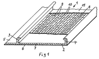
- the cuff 1 shows a sleeve 1 in the stretched state, as is used, for example, to encase a cable splice, not shown.
- the cuff 1 consists essentially of a band 2, with webs 3 and 4 running on its longitudinal edges, via which, after laying around the cable splice in a manner not shown, a rail is pushed around the band edges of the band 2 in the position formed into the tube during of the shrinking process.
- the band 2 also has a tab 5 which, after the band 2 has been formed, comes to rest under the web 4 to form the tube. 6 is also an adhesive layer.
- the cuffs known so far consist of cross-linked polyethylene. When heat shrink showed improper handling z. B. due to local overheating of the cuff cracks in the cuff, which made it unusable.
- the cuff 1 consists of a multilayer structure.
- the flap 5, the webs 3 and 4 and the region 7 of the sleeve 1 connecting the webs 3 and 4 to one another consist of cross-linked polyethylene, preferably of a polyethylene, to which silane groups are grafted and which has been cross-linked in the presence of moisture.
- a layer 8 of a thermoplastic adhesive, advantageously based on ethylene-vinyl acetate, is arranged on the area 7 of the cuff 1 located between the webs 3 and 4.
- Embedded in the layer 8 is a multitude of fibers 9, which consist of a cross-linked polyethylene.
- These fibers 9 are made from waste material which incurred in the manufacture of shrink articles and which, since it cannot be reprocessed in contrast to non-cross-linked polyethylene, causes problems during disposal.
- the fibers 9, which were arranged in the layer 8 before the stretching process in an irregular distribution, were mainly aligned in the stretching direction by the stretching process. However, they have no connection with the threads 10.
- the fibers 9 are also stretched, although they are arranged in the layer 8 which also softens during the stretching process. Since the cuff 1 is cooled in the stretched state after the stretching process, the fibers 9 can also be heat-shrunk and support the shrinking effect of the layer 7. Above the layer 8 there is a layer 11 made of thermoplastic polyethylene, which prevents the layer 7 from overheating locally .
- thermoplastic layer 11 If a crack occurs on the surface of the sleeve 1, it will only spread to the next fiber 9 or thread 10 and can be covered by the thermoplastic layer 11.
- the fibers 9 advantageously have a length of 10-35 mm and a cross section of 1 to 1.5 mm2.
- the fibers 9 are made by machining waste material from cross-linked polyethylene z. B. produced by milling or planing. Due to the manufacturing process, they have an essentially rectangular cross section. Since the fibers 9 are also stretched during the stretching process, as described above, the short side of the rectangle should not be less than 0.2 mm.
- the fill factor of layer 8 with the fibers is between 15 and 45%, preferably 25-35%, based on the volume of the layer 8.
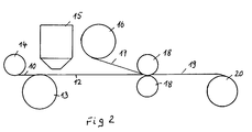
- the cuff 1 can be produced very economically. This will be explained in more detail using an exemplary embodiment with the inclusion of FIGS. 2 and 3.
- a tape 12 made of a thermoplastic adhesive made of ethyl-vinyl acetate copolymer is continuously drawn off from a supply roll 13.
- the threads 10, of which only one is drawn for the sake of clarity, are drawn off from supply drums 14 at the same speed and placed on the surface of the belt 12.
- the fibers 9 are applied to the surface of the belt 12 in a random distribution from a storage container 15.
- the tape 12 is covered by the tape 17 drawn off from a supply roll 16, which has the same width, wall thickness and composition as the tape 12.
- a pair of rollers 18 is used to produce a laminate tape 19 from the tapes 12 and 17 as well as the fibers 9 and the threads 10, which tape is wound onto a supply reel 20.
- the tape 19 is laminated under pressure and heat.
- the rollers of the pair of rollers 18 are heated.
- the laminate tape 19 is fed into an extruder 21, which the laminate tape 19 from both sides with the layers 7 and 11 coated.
- Layer 7 is produced from a mixture that consists of 50 parts of polyethylene 40 parts of ethylene-vinyl acetate copolymer 10 parts of carbon black put together.
- silane-based crosslinking agent is added to this mixture.
- the layer 11 consists of almost pure polyethylene.
- the composite profile 22 emerging from the mouthpiece of the extruder 21 has the cross section of the sleeve as shown in FIG. 1, but the width is considerably smaller. Due to the extrusion temperature of approx. 210 ° C, an intimate connection between the layers 7, 8 and 11 is created.
- the composite profile can be cut into the desired lengths behind the extruder or wound up. After extrusion, the layer 7 of the profile 22 is crosslinked in the presence of water vapor and at a temperature of 90 ° C. within a time of approximately 36 hours.
- the profile 22 is heated to a temperature of approx. 170 ° C., stretched at this temperature by approx. 300 to 400%, specifically in the transverse direction to the course of the webs 3 and 4 and cooled in the stretched state.
Landscapes
- Engineering & Computer Science (AREA)
- Mechanical Engineering (AREA)
- Chemical & Material Sciences (AREA)
- Environmental & Geological Engineering (AREA)
- Health & Medical Sciences (AREA)
- Spectroscopy & Molecular Physics (AREA)
- Chemical Kinetics & Catalysis (AREA)
- Medicinal Chemistry (AREA)
- Polymers & Plastics (AREA)
- Organic Chemistry (AREA)
- Physics & Mathematics (AREA)
- Composite Materials (AREA)
- Compositions Of Macromolecular Compounds (AREA)
- Laminated Bodies (AREA)
- Shaping By String And By Release Of Stress In Plastics And The Like (AREA)
- Wrappers (AREA)
- Processes Of Treating Macromolecular Substances (AREA)
- Thermotherapy And Cooling Therapy Devices (AREA)
- Organic Insulating Materials (AREA)
- Manufacture Of Macromolecular Shaped Articles (AREA)
Description
- Die Erfindung betrifft einen wärmeschrumpfbaren Gegenstand zum Umhüllen eines Substrates, enthaltend Elemente aus einem vernetzten Polymeren, der durch Erwärmen des Gegenstandes über den Kristallitschmelzpunkt des vernetzten Polymeren, Recken bei dieser Temperatur und Abkühlen im gereckten Zustand hergestellt ist.
- Wärmeschrumpfende Gegenstände finden Verwendung für die Umhüllung von langgestreckten Gegenständen, um diese z. B. gegen Witterungseinflüsse von außen abzudichten. Ein häufiges Anwendungsgebiet ist die Umhüllung von Verbindungsstellen elektrischer Kabel. Für diesen Anwendungszweck ist eine Manschette aus wärmeschrumpfendem Kunststoff entwickelt worden, welche aus einem Band mit an zwei Längskanten angeordneten Stegen besteht. Nach dem Herumlegen der Manschette um den Kabelspleiß wird eine Verschlußschiene über die Stege geschoben, so daß die Manschette den Kabelspleiß in Form eines Rohres umgibt (DE-C3-15 25 815). Die Manschette weist an ihrer dem Kabelspleiß zugekehrten Oberfläche eine Kleberbeschichtung auf, die beim Schrumpferwärmen plastisch wird und während des Schrumpfvorgangs die Hohlräume zwischen der Manschette und dem Kabelspleiß und den Kabelmänteln ausfüllt. Der Kabelspleiß wird häufig noch durch einen sogenannten Liner umhüllt, welcher aus einem zum Rohr geformten Band besteht. Durch besonders gestaltete Endbereiche des Liners ergibt sich ein allmählicher Übergang von dem relativ großen Durchmesser des Kabelspleißes zu den Kabelmänteln (DE-A1-23 45 326).
- Durch innere Spannungen, durch mechanische Einflüsse aber auch durch unsachgemäßes vorgehen beim Wärmeschrumpfen, in dem z. B. die Manschette örtlich überhitzt wird, kann es zu einer Rißbildung der Manschette kommen, wodurch diese unbrauchbar wird. Auch eine oberflächliche Beschädigung der Manschette kann dazu führen, daß diese beim Wärmeschrumpfen einreißt.
- In der EP-A-0 116 393 wird ein wärmeschrumpfender Gegenstand vorgeschlagen, welcher aus einem Gewebe besteht, dessen Schrumpfeigenschaft durch in Schrumpfrichtung verlaufende wärmeschrumpfende Fäden erreicht wird. Quer zur Schrumpfrichtung verlaufen Fäden aus nicht schrumpfendem hochfestem Werkstoff. Das Gewebe ist an seiner dem zu umhüllenden Substrat abgekehrten Oberfläche mit einem Polymermaterial und an seiner dem Substrat zugekehrten Oberfläche mit einem wärmeaktivierbaren Kleber beschichtet. Da das Herstellen der wärmeschrumpfbaren Fäden und deren Verwebung mit den hochfesten Fäden ein aufwendiger Arbeitsgang ist, ist ein solcher Gegenstand nicht wirtschaftlich. Darüberhinaus besteht die Gefahr, daß die dem Substrat zugekehrte wärmeaktivierbare Schicht, die bei Schrumpftemperatur zähflüssig wird, bei größeren Maschenweiten beim Schrumpfen durch die Maschen des Gewebes nach außen gepreßt wird. Ein weiterer wesentlicher Nachteil ist, daß bei Durchtrennung oder Abriß von mehreren wärmeschrumpfbaren Fäden das Gewebe seine Schrumpfeigenschaft weitestgehend einbüßt.
- Der vorliegenden Erfindung liegt die Aufgabe zugrunde, einen wärmeschrumpfbaren Gegenstand anzugeben, der gegen Überhitzung und mechanische Beschädigungen wesentlich unempfindlicher ist und der sich wesentlich wirtschaftlicher herstellen läßt.
- Diese Aufgabe wird bei einem Gegenstand der eingangs erwähnten Art dadurch gelöst, daß nach einer ersten Alternative das vernetzte Polymer in Form von Partikeln als Füllstoff in einem thermoplastischen Kunststoff vorliegt oder nach einer zweiten Alternative der Gegenstand an seiner dem Substrat abgekehrten Oberfläche eine Schicht aus einem Thermoplasten aufweist, in welcher Fasern aus einem vernetzten Polymeren in ungeregelter Verteilung angeordnet sind. Die auf einen herkömmlichen wärmeschrumpfbaren Gegenstand außenseitig aufgebrachte Schicht hat den wesentlichen Vorteil, daß sie sich beim Reckvorgang nach der Vernetzung wie die vernetzte Schicht verhält und den Reckvorgang, ohne Schaden zu nehmen, mitmacht. Sowohl bei dem Band aus einem thermoplastischen Kunststoff, in welchem die Partikel aus dem vernetzten Polymeren in gerecktem Zustand vorliegen als auch bei dem Gegenstand, bei dem eine Schicht aus einem vernetzten Polymeren mit einer Schicht aus einem Thermoplasten mit eingelagerter Partikeln aus dem vernetzten Polymeren versehen ist, richten sich die Fasern bzw. Partikel aus dem vernetzten Polymer überwiegend in Richtung der Reckkraft aus. Völlig überraschend hat sich gezeigt, daß die Fasern zusätzlich ebenfalls gereckt werden, obwohl sie sich in einer beim Reckvorgang erweichten Masse befinden. Dementsprechend bilden sie sich beim Schrumpferwärmen zurück und unterstützen dabei die Schrumpfwirkung der vernetzten Schicht.
- Zusätzlich zu den Fasern können in der Schicht aus Thermoplast Fäden aus Glasfasern, Polyester, Polyamid oder einem vernetzten Polymeren quer zur Schrumpfrichtung in nahezu gleichem Abstand zueinander verlaufen. Diese hochfesten Fäden, die sich im Gegensatz zu den Fasern von einem Ende bis zum anderen Ende des Gegenstandes erstrecken, sollen dem wärmeschrumpfenden Gegenstand bei Schrumpftemperatur zusätzlich als mechanische Stütze dienen. Wesentlich ist aber, daß sie wie auch die Fasern, falls sich ein Riß in der vernetzten Schicht gebildet haben sollte, dessen Länge bzw. Tiefe begrenzen.
- Als vernetztes Polymer wird vorteilhafterweise Polyethylen verwendet, welches chemisch vernetzt ist, und zwar zweckmäßigerweise ein Polyethylen, dem Silangruppen aufgepfropft sind und welches daher bei Anwesenheit von Feuchtigkeit vernetzbar ist.
- Nach einer Weiterbildung der Erfindung ist die die Fasern enthaltende Schicht von einer Schicht aus thermoplastischem Kunststoff überdeckt. Bei einer solchen Anordnung besteht ein fester Verbund zwischen den einzelnen Schichten. Die weitere thermoplastische Schicht sorgt beim Schrumpferwärmen für eine Vergleichmäßigung der Oberflächentemperatur und hält Überhitzungen von der vernetzten Schicht ab.
- Die Erfindung ist bei nahezu jeder Art von Schrumpfartikel anwendbar. Mit besonderem Vorteil ist sie jedoch bei sogenannten Manschetten einsetzbar.
- Eine solche Manschette besteht aus einem Band aus vernetztem Polymer, mit an zwei einander gegenüberliegenden Kanten verlaufenden Stegen, über die nach dem Herumlegen der Manschette um das zu umhüllende Substrat eine Halteschiene geschoben wird, welche die Bandkanten beim Wärmeschrumpfen zusammenhält. Bei einer solchen Manschette befinden sich sowohl die die Fasern bzw. ggfs die Fäden enthaltende Schicht als auch die thermoplastische Deckschicht in dem Bereich zwischen den Stegen.
- Für die Wirkung der Fasern ist wichtig, daß diese eine Länge von zwischen 0,5 und 50 mm vorzugsweise zwischen 10 und 35 mm aufweisen. Da die Fasern wie oben erwähnt beim Reckvorgang ebenfalls gereckt werden, sollte die Querschnittsfläche der Fasern mindestens 1 mm² betragen. Die Fasern werden zweckmäßigerweise aus Abfallmaterial abgespant, beispielsweise durch Fräsen oder Hobeln. Ihr Querschnitt ist daher im wesentlichen rechteckig. Die kleinste Seite dieser Rechtecke sollte einen Wert von 0,5 mm nicht unterschreiten. Die die Fasern und ggfs die Fäden aufnehmende Schicht besteht zweckmäßigerweise aus Ethylen-Vinylazetat-Copolymer.
- Die Erfindung betrifft weiterhin ein Verfahren zur Herstellung eines wärmeschrumpfenden Gegenstandes. Bei diesem Verfahren wird zunächst ein aus einem vernetzbaren Polymeren und der die Fasern und ggf. die Fäden enthaltenden thermoplastischen Schicht bestehender Rohling hergestellt. Die vernetzbare Schicht des Rohlings wird dann vernetzt, und anschließend daran der Rohling über den Kristallitschmelzpunkt der vernetzten Schicht erwärmt, im erwärmten Zustand gereckt und im gereckten Zustand abgekühlt. Da beim Extrudieren der thermoplastischen Schicht die Gefahr besteht, daß die Fasern durch die in den Extruderschnecken auftretenden Scherkräfte zermahlen werden, hat es sich als sinnvoll erwiesen, die thermoplastische Schicht mit den eingebetteten Fasern als Band in den Extruder einlaufen zu lassen und die vernetzbare Schicht an das Band anzuextrudieren. Im gleichen Arbeitsgang kann auf das Band an der der vernetzbaren Schicht gegenüberliegenden Seite des Bandes eine thermoplastische Schicht aufextrudiert werden.
- Das Band, welches in den Extruder einläuft, kann dadurch hergestellt werden, daß man zwei dünnwandige Bänder vorzugsweise aus einem thermoplastischen Kleber laminiert, wobei zwischen den Bändern die Fasern und ggfs auch die Fäden angeordnet werden. Zum Laminieren verwendet man zweckmäßigerweise ein beheiztes Walzenpaar, durch welches die Bänder unter gleichzeitiger Dickenabnahme hindurchgeführt werden. Andererseits besteht auch die Möglichkeit, auf ein Band vorzugsweise aus einem thermoplastischen Kleber die Fasern in ungleichmäßiger Verteilung aufzubringen und diese mittels eines beheizten Walzenpaares in eine der Oberflächen des Bandes einzuwalzen. Im gleichen Arbeitsgang können die Fäden in Längsrichtung des Bandes eingewalzt werden. Vorteilhaft ist es ferner, wenn die miteinander zu verbindenden Oberflächen der Bänder vor dem Laminieren aufgeheizt werden.
- Die Erfindung ist an Hand der in den Figuren 1 bis 3 schematisch dargestellten Ausführungsbeispiele näher erläutert.
- In der Figur 1 ist eine Manschette 1 im gereckten Zustand dargestellt, wie sie beispielsweise zum Umhüllen eines nicht dargestellten Kabelspleißes verwendet wird. Die Manschette 1 besteht im wesentlichen aus einem Band 2, mit an seinen Längskanten verlaufenden Stegen 3 und 4, über die nach dem Herumlegen um den Kabelspleiß in nicht dargestellter Weise eine Schiene geschoben wird um die Bandkanten des Bandes 2 in der zum Rohr geformten Lage während des Schrumpfprozesses zu halten. Das Band 2 weist noch eine Lasche 5 auf, welche nach dem Formen des Bandes 2 zum Rohr unter dem Steg 4 zu liegen kommt. Mit 6 ist noch eine Kleberschicht bezeichnet. Die bisher bekannten Manschetten bestehen aus vernetztem Polyethylen. Beim Schrumpferwärmen zeigten sich bei unsachgemäßer Handhabung z. B. infolge örtlicher Überhitzung der Manschette Risse in der Manschette, welche diese unbrauchbar machten.
- Zur Verringerung der Rißneigung besteht die Manschette 1 nach der Lehre der Erfindung aus einem mehrschichtigen Aufbau. Die Lasche 5, die Stege 3 und 4 sowie der die Stege 3 und 4 miteinander verbindende Bereich 7 der Manschette 1 bestehen aus vernetztem Polyethylen, vorzugsweise aus einem Polyethylen, dem Silangruppen aufgepfropft sind und welches bei Anwesenheit von Feuchtigkeit vernetzt wurde. Auf dem zwischen den Stegen 3 und 4 befindlichen Bereich 7 der Manschette 1 ist eine Schicht 8 aus einem thermoplastischen Kleber vorteilhafterweise auf der Basis Ethylen-Vinyl-Azetat angeordnet. Eingebettet in der Schicht 8 ist eine Vielzahl von Fasern 9, welche aus einem vernetzten Polyethylen bestehen. Diese Fasern 9 sind aus Abfallmaterial hergestellt, welches bei der Herstellung von Schrumpfartikeln anfällt und welches, da es im Gegensatz zu unvernetztem Polyethylen nicht wieder aufzuarbeiten ist, bei der Entsorgung Probleme bereitet. Mit 10 sind Fäden aus einem bei Reck- bzw. Schrumpftemperatur mechanisch beständigem Werkstoff z. B. Polyamid, Polyester, Polyaramid o. ä. bezeichnet, welche in nahezu gleichem Abstand zueinander parallel zu den Stegen 3 und 4 verlaufen und sich im Gegensatz zu den Fasern 9 von einem Ende der Manschette 1 bis zu ihrem anderen Ende erstrecken. Die Fasern 9 die in der Schicht 8 vor dem Reckvorgang in unregelmäßiger Verteilung angeordnet waren, sind durch den Reckvorgang überwiegend in Reckrichtung ausgerichtet worden. Sie haben aber keine Verbindung mit den Fäden 10. Beim Reckvorgang werden auch die Fasern 9 gereckt, obwohl sie in der beim Reckvorgang ebenfalls erweichenden Schicht 8 angeordnet sind. Da nach dem Reckvorgang die Manschette 1 im gereckten Zustand abgekühlt wird, sind also auch die Fasern 9 wärmeschrumpfbar und unterstützen die Schrumpfwirkung der Schicht 7. Oberhalb der Schicht 8 ist noch eine Schicht 11 aus thermoplastischem Polyethylen angeordnet, die eine örtliche Überhitzung der Schicht 7 verhindert.
- Sollte ein Riß an der Oberfläche der Manschette 1 auftreten, so wird sich dieser nur bis zur nächsten Faser 9 bzw. zum nächsten Faden 10 ausbreiten und durch die thermoplastische Schicht 11 überdecken lassen.
- Die Fasern 9 haben zweckmäßigerweise eine Länge von 10 - 35 mm und einen Querschnitt von 1 bis 1,5 mm². Die Fasern 9 werden durch spanende Bearbeitung von Abfallmaterial aus vernetztem Polyethylen z. B. durch Fräsen oder Hobeln hergestellt. Herstellungsbedingt zeigen sie einen im wesentlich rechteckigen Querschnitt. Da die Fasern 9 wie oben beschrieben, beim Reckvorgang ebenfalls gereckt werden, sollte die kurze Seite des Rechtecks einen Wert von 0,2 mm nicht unterschreiten. Der Füllfaktor der Schicht 8 mit den Fasern beträgt zwischen 15 und 45 %, vorzugsweise 25 - 35 % bezogen auf das Volumen der Schicht 8. Die Fäden 10, zweckmäßigerweise verwendet man Polyesterfäden, haben einen Durchmesser von 0,05 - 0,2 mm und einen Abstand von in etwa 2 bis 4 mm zueinander.
- Neben den genannten Vorteilen ist die Manschette 1 sehr wirtschaftlich herstellbar. Dies soll an Hand eines Ausführungsbeispiels unter Einbeziehung der Figuren 2 und 3 näher erläutert werden.
- Ein Band 12 aus einem thermoplastischen Kleber aus Ethyl-Vinylazetat-Copolymer wird von einem Vorratswickel 13 kontinuierlich abgezogen. Die Fäden 10 von denen der Deutlichkeit halber nur einer gezeichnet ist, werden von Vorratstrommeln 14 mit gleicher Geschwindigkeit abgezogen und auf die Oberfläche des Bandes 12 aufgelegt. Von einem Vorratsbehälter 15 werden die Fasern 9 in willkürlicher Verteilung auf die Oberfläche des Bandes 12 aufgebracht. Durch das von einem Vorratswickel 16 abgezogene Band 17, welches die gleiche Breite, Wanddicke und Zusammensetzung wie das Band 12 hat, wird das Band 12 bedeckt. Durch ein Walzenpaar 18 wird aus den Bändern 12 und 17 sowie den Fasern 9 und den Fäden 10 ein Laminatband 19 hergestellt, welches auf eine Vorratsspule 20 aufgewickelt wird. Das Laminieren des Bandes 19 erfolgt unter Druck und Wärme. Hierzu werden die Walzen des Walzenpaares 18 aufgeheizt. Alternativ besteht jedoch auch die Möglichkeit, die Oberfläche der Bänder 12 und 17 und/oder die Fasern 9 und die Fäden 10 vor dem Eintritt in den Walzspalt auf eine Temperatur zu erhöhen, welche oberhalb des Erweichungspunktes des thermoplastischen Klebers, jedoch unterhalb des Erweichungspunktes der Fasern 9 und der Fäden 10 liegt. Dies könnte z. B. durch Infraroterhitzung vorgenommen werden.
- Das Laminatband 19 wird in einen Extruder 21 eingefahren, der das Laminatband 19 von beiden Seiten mit den Schichten 7 und 11 beschichtet. Die Schicht 7 wird aus einer Mischung erzeugt, die sich aus
50 Teilen Polyethylen
40 Teilen Ethylen-Vinylazetat-Copolymer
10 Teilen Ruß
zusammensetzt. Bei Eintritt in den Extruder 21 wird dieser Mischung 1 % Vernetzungsmittel auf Silanbasis zugegeben. Die Schicht 11 besteht aus nahezu reinem Polyethylen. - Das aus dem Mundstück des Extruders 21 austretende Verbundprofil 22 hat den Querschnitt der Manschette wie sie in Figur 1 dargestellt ist, wobei jedoch die Breite wesentlich geringer ist. Infolge der Extrusionstemperatur von ca. 210 °C entsteht eine innige Verbindung zwischen den Schichten 7, 8 und 11 untereinander.
- Das Verbundprofil kann hinter dem Extruder in gewünschte Längen geschnitten werden oder aber aufgewickelt werden. Nach dem Extrudieren wird die Schicht 7 des Profils 22 bei Anwesenheit von Wasserdampf und bei einer Temperatur von 90 °C innerhalb einer Zeit von ca. 36 Stunden vernetzt.
- Anschließend wird das Profil 22 auf eine Temperatur von ca. 170 °C erwärmt, bei dieser Temperatur um ca. 300 bis 400 % gereckt und zwar in Querrichtung zum Verlauf der Stege 3 und 4 und im gereckten Zustand abgekühlt.
- Abschließend wird eine Schicht 6 aus einem Heißschmelzkleber aufgebracht und die gewünschte Länge von dem Profil 22 abgetrennt. Damit ist die Manschette 1 fertiggestellt und kann in Benutzung genommen werden.
Claims (7)
- Wärmeschrumpfender Gegenstand zum Umhüllen eines Substrates, enthaltend Elemente aus einem vernetzten Polymeren, der durch Erwärmen des Gegenstandes über den Kristallitschmelzpunkt des vernetzten Polymeren, Recken bei dieser Temperatur und Abkühlen im gereckten Zustand hergestellt ist, dadurch gekennzeichnet, daß das vernetzte Polymer in Form von Partikeln (9) als Füllstoff in einer Schicht (8) aus einem thermoplastischen Kunststoff vorliegt.
- Wärmeschrumpfender Gegenstand nach Anspruch 1, dadurch gekennzeichnet, daß in der thermoplastischen Schicht (8) Fäden (10) aus Glasfasern, Polyester, Polyamid oder einem vernetzten Polymeren quer zur Schrumpfrichtung in nahezu gleichen Abstand zueinander verlaufen und sich über die gesamte Länge des Gegenstandes erstrecken.
- Wärmeschrumpfender Gegenstand zum Umhüllen eines Substrates, enthaltend Elemente aus einem vernetzten Polymeren, der durch Erwärmen des Gegenstandes über den Kristallitschmelzpunkt des vernetzten Polymeren, Recken bei dieser Temperatur und Abkühlen im gereckten Zustand hergestellt ist, dadurch gekennzeichnet, daß der Gegenstand (1) an seiner dem Substrat abgekehrten Oberfläche eine Schicht (8) aus einem Thermoplasten aufweist, in welcher Fasern (9) aus einem vernetzten Polymeren in ungeregelter Verteilung angeordnet sind.
- Wärmeschrumpfender Gegenstand nach Anspruch 1 oder einem der darauffolgenden, dadurch gekennzeichnet, daß die die Fasern (9) enthaltende Schicht (8) von einer Schicht (11) aus einem thermoplastischen Kunststoff überdeckt ist.
- Wärmeschrumpfender Gegenstand nach Anspruch 1 oder einem der darauffolgenden in Form eines Bandes mit an zwei einander gegenüberliegenden Randbereichen verlaufenden Stegen (3,4) zum Überschieben einer Schiene, die die Kanten nach dem Herumlegen um das Substrat zusammenhält, dadurch gekennzeichnet, daß sowohl die Schicht (8) aus dem Thermoplasten, welche die Fasern (9) enthält, als auch die Deckschicht (11) aus dem Thermoplasten lediglich zwischen den Stegen (3,4) angeordnet ist.
- Wärmeschrumpfender Gegenstand nach Anspruch 1 oder einem der darauffolgenden, dadurch gekennzeichnet, daß die die Fasern (9) und ggfs. die Fäden (10) aufweisende Schicht (8) aus Ethylen-Vinylazetat-Copolymer besteht.
- Verfahren zur Herstellung eines wärmeschrumpfenden Gegenstandes nach Anspruch 1 oder einem der darauffolgenden, dadurch gekennzeichnet, daß ein aus einem vernetzbaren Polymeren und der Schicht (8) oder den Schichten (8,11) aus Thermoplasten bestehender Rohling hergestellt wird, daß die vernetzbare Schicht (2) vernetzt wird, daß der Rohling über den Kristallitschmelzpunkt des vernetzten Polymers erwärmt, gereckt und in gerecktem Zustand abgekühlt wird.
Applications Claiming Priority (4)
| Application Number | Priority Date | Filing Date | Title |
|---|---|---|---|
| DE3737005 | 1987-10-31 | ||
| DE19873737004 DE3737004A1 (de) | 1987-10-31 | 1987-10-31 | Extrudierbare kunststoffmischung |
| DE19873737005 DE3737005A1 (de) | 1987-10-31 | 1987-10-31 | Waermeschrumpfender gegenstand und verfahren zu seiner herstellung |
| DE3737004 | 1987-10-31 |
Publications (3)
| Publication Number | Publication Date |
|---|---|
| EP0314907A2 EP0314907A2 (de) | 1989-05-10 |
| EP0314907A3 EP0314907A3 (en) | 1990-11-22 |
| EP0314907B1 true EP0314907B1 (de) | 1994-11-30 |
Family
ID=25861349
Family Applications (1)
| Application Number | Title | Priority Date | Filing Date |
|---|---|---|---|
| EP19880115105 Expired - Lifetime EP0314907B1 (de) | 1987-10-31 | 1988-09-15 | Wärmeschrumpfbarer Gegenstand |
Country Status (5)
| Country | Link |
|---|---|
| EP (1) | EP0314907B1 (de) |
| JP (1) | JPH01161059A (de) |
| AT (1) | ATE114703T1 (de) |
| DE (1) | DE3852274D1 (de) |
| ES (1) | ES2067462T3 (de) |
Families Citing this family (2)
| Publication number | Priority date | Publication date | Assignee | Title |
|---|---|---|---|---|
| ATE105229T1 (de) * | 1990-03-08 | 1994-05-15 | Rxs Schrumpftech Garnituren | Waermeschrumpfbare umhuellung. |
| EP0679487A1 (de) * | 1994-04-28 | 1995-11-02 | W.R. Grace & Co.-Conn. | Mehrschichtige Polyolefinfolie mit recycliertem Polymer aus vernetzten Filmen |
Citations (1)
| Publication number | Priority date | Publication date | Assignee | Title |
|---|---|---|---|---|
| EP0116393A2 (de) * | 1983-01-06 | 1984-08-22 | RAYCHEM CORPORATION (a Delaware corporation) | Dimensionsrückstellbarer Gegenstand |
Family Cites Families (4)
| Publication number | Priority date | Publication date | Assignee | Title |
|---|---|---|---|---|
| GB2072683A (en) * | 1979-06-11 | 1981-10-07 | Speirs G K | Method of producing thermoplastics extrusions using scrap materials |
| GB8300218D0 (en) * | 1983-01-06 | 1983-02-09 | Raychem Corp | Dimensionally recoverable article |
| DD227380A1 (de) * | 1984-06-07 | 1985-09-18 | Plastik Werk Berlin Veb | Verwendung ein- oder mehrfach vorplastizierter duroplastischer formmasse |
| DE3620321A1 (de) * | 1986-06-18 | 1987-12-23 | Remaplan Gmbh | Werkstoff aus kunststoff |
-
1988
- 1988-09-15 EP EP19880115105 patent/EP0314907B1/de not_active Expired - Lifetime
- 1988-09-15 AT AT88115105T patent/ATE114703T1/de not_active IP Right Cessation
- 1988-09-15 ES ES88115105T patent/ES2067462T3/es not_active Expired - Lifetime
- 1988-09-15 DE DE3852274T patent/DE3852274D1/de not_active Expired - Fee Related
- 1988-10-19 JP JP63261682A patent/JPH01161059A/ja active Pending
Patent Citations (1)
| Publication number | Priority date | Publication date | Assignee | Title |
|---|---|---|---|---|
| EP0116393A2 (de) * | 1983-01-06 | 1984-08-22 | RAYCHEM CORPORATION (a Delaware corporation) | Dimensionsrückstellbarer Gegenstand |
Also Published As
| Publication number | Publication date |
|---|---|
| EP0314907A3 (en) | 1990-11-22 |
| JPH01161059A (ja) | 1989-06-23 |
| EP0314907A2 (de) | 1989-05-10 |
| ATE114703T1 (de) | 1994-12-15 |
| ES2067462T3 (es) | 1995-04-01 |
| DE3852274D1 (de) | 1995-01-12 |
Similar Documents
| Publication | Publication Date | Title |
|---|---|---|
| DE69411389T2 (de) | Verbundbahn aus gegenseitigen parallelen fasern in einer matrix | |
| DE2848231C2 (de) | Wärmerückstellfähiger Gegenstand | |
| EP0013046B1 (de) | Verfahren zum simultanen biaxialen Recken einer Folie aus Kunststoff und Vorrichtung zur Durchführung des Verfahrens | |
| EP0330873B1 (de) | Wärmerückstellbarer Gegenstand zum Umhüllen eines Substrates | |
| DE68902483T2 (de) | Verfahren und anlage zur herstellung eines bandes, das aus mindestens einem garn besteht, das mit einem thermoplastischen polymer impraegniert ist. | |
| EP0257223A1 (de) | Verfahren zum Umhüllen von langgestrecktem Gut | |
| EP0326928B1 (de) | Verfahren und Vorrichtung zum abschnittsweisen Ummanteln von Objekten mit Kunststoff | |
| DE3737005A1 (de) | Waermeschrumpfender gegenstand und verfahren zu seiner herstellung | |
| EP0314907B1 (de) | Wärmeschrumpfbarer Gegenstand | |
| DE3929859A1 (de) | Verfahren zur herstellung von schrumpfartikeln | |
| DE3111064C2 (de) | Schrumpfbares Material mit einer Beschichtung aus Schmelzkleber | |
| DE1704900A1 (de) | Verfahren zur Herstellung von Schichtstoffen | |
| EP0570997B1 (de) | Verfahren zur Herstellung eines wärmerückstellbaren Bandes aus Kunststoff | |
| DE3717618A1 (de) | Waermerueckstellbarer gegenstand und verfahren zu seiner herstellung | |
| EP0445381B1 (de) | Wärmeschrumpfbare Umhüllung | |
| DE3724514A1 (de) | Verfahren zur kontinuierlichen herstellung von abzweigkappen bzw. aufteilungskappen aus waermerueckstellbarem kunststoff | |
| DE4142045C2 (de) | Verfahren zur Herstellung eines Kunststoffkörpers | |
| DE3738586A1 (de) | Umwickelmuffe zum umhuellen von kabeln, leitungsrohren u. ae. | |
| DE4200251A1 (de) | Waermerueckstellbarer gegenstand | |
| DE3831996A1 (de) | Verfahren zum herstellen von waermerueckstellbaren baendern aus kunststoff | |
| EP0464429B1 (de) | Verfahren zum Herstellen einer wärmerückstellbaren Werkstoffbahn | |
| DE19504921C2 (de) | Verfahren und Vorrichtung zur Behandlung von Kunststoff-Bahnmaterial | |
| EP0423551B1 (de) | Wärmeschrumpfbare Umhüllung mit einer Verstärkungseinlage | |
| CH453681A (de) | Fadenverstärktes Harzband | |
| DE3921490A1 (de) | Verfahren zum herstellen eines mit einem gewebe verstaerkten kunststoffbandes |
Legal Events
| Date | Code | Title | Description |
|---|---|---|---|
| PUAI | Public reference made under article 153(3) epc to a published international application that has entered the european phase |
Free format text: ORIGINAL CODE: 0009012 |
|
| AK | Designated contracting states |
Kind code of ref document: A2 Designated state(s): AT BE CH DE ES FR GB GR IT LI NL SE |
|
| PUAL | Search report despatched |
Free format text: ORIGINAL CODE: 0009013 |
|
| AK | Designated contracting states |
Kind code of ref document: A3 Designated state(s): AT BE CH DE ES FR GB GR IT LI NL SE |
|
| 17P | Request for examination filed |
Effective date: 19901015 |
|
| 17Q | First examination report despatched |
Effective date: 19920713 |
|
| GRAA | (expected) grant |
Free format text: ORIGINAL CODE: 0009210 |
|
| AK | Designated contracting states |
Kind code of ref document: B1 Designated state(s): AT BE CH DE ES FR GB GR IT LI NL SE |
|
| PG25 | Lapsed in a contracting state [announced via postgrant information from national office to epo] |
Ref country code: NL Effective date: 19941130 |
|
| REF | Corresponds to: |
Ref document number: 114703 Country of ref document: AT Date of ref document: 19941215 Kind code of ref document: T |
|
| ITF | It: translation for a ep patent filed | ||
| REF | Corresponds to: |
Ref document number: 3852274 Country of ref document: DE Date of ref document: 19950112 |
|
| GBT | Gb: translation of ep patent filed (gb section 77(6)(a)/1977) |
Effective date: 19941220 |
|
| ET | Fr: translation filed | ||
| REG | Reference to a national code |
Ref country code: GR Ref legal event code: FG4A Free format text: 3014204 |
|
| REG | Reference to a national code |
Ref country code: ES Ref legal event code: FG2A Ref document number: 2067462 Country of ref document: ES Kind code of ref document: T3 |
|
| NLV1 | Nl: lapsed or annulled due to failure to fulfill the requirements of art. 29p and 29m of the patents act | ||
| PGFP | Annual fee paid to national office [announced via postgrant information from national office to epo] |
Ref country code: GR Payment date: 19950831 Year of fee payment: 8 |
|
| PGFP | Annual fee paid to national office [announced via postgrant information from national office to epo] |
Ref country code: FR Payment date: 19950904 Year of fee payment: 8 |
|
| PGFP | Annual fee paid to national office [announced via postgrant information from national office to epo] |
Ref country code: SE Payment date: 19950912 Year of fee payment: 8 Ref country code: AT Payment date: 19950912 Year of fee payment: 8 |
|
| PGFP | Annual fee paid to national office [announced via postgrant information from national office to epo] |
Ref country code: ES Payment date: 19950919 Year of fee payment: 8 |
|
| PG25 | Lapsed in a contracting state [announced via postgrant information from national office to epo] |
Ref country code: LI Effective date: 19950930 Ref country code: CH Effective date: 19950930 |
|
| PLBE | No opposition filed within time limit |
Free format text: ORIGINAL CODE: 0009261 |
|
| STAA | Information on the status of an ep patent application or granted ep patent |
Free format text: STATUS: NO OPPOSITION FILED WITHIN TIME LIMIT |
|
| 26N | No opposition filed | ||
| REG | Reference to a national code |
Ref country code: CH Ref legal event code: PL |
|
| PG25 | Lapsed in a contracting state [announced via postgrant information from national office to epo] |
Ref country code: AT Effective date: 19960915 |
|
| PG25 | Lapsed in a contracting state [announced via postgrant information from national office to epo] |
Ref country code: SE Effective date: 19960916 Ref country code: ES Free format text: LAPSE BECAUSE OF THE APPLICANT RENOUNCES Effective date: 19960916 |
|
| PG25 | Lapsed in a contracting state [announced via postgrant information from national office to epo] |
Ref country code: FR Effective date: 19960930 |
|
| PG25 | Lapsed in a contracting state [announced via postgrant information from national office to epo] |
Ref country code: GR Free format text: THE PATENT HAS BEEN ANNULLED BY A DECISION OF A NATIONAL AUTHORITY Effective date: 19970331 |
|
| REG | Reference to a national code |
Ref country code: GR Ref legal event code: MM2A Free format text: 3014204 |
|
| EUG | Se: european patent has lapsed |
Ref document number: 88115105.4 |
|
| REG | Reference to a national code |
Ref country code: FR Ref legal event code: ST |
|
| REG | Reference to a national code |
Ref country code: FR Ref legal event code: ST |
|
| PGFP | Annual fee paid to national office [announced via postgrant information from national office to epo] |
Ref country code: GB Payment date: 19990813 Year of fee payment: 12 |
|
| PGFP | Annual fee paid to national office [announced via postgrant information from national office to epo] |
Ref country code: DE Payment date: 19990820 Year of fee payment: 12 |
|
| PGFP | Annual fee paid to national office [announced via postgrant information from national office to epo] |
Ref country code: BE Payment date: 19990827 Year of fee payment: 12 |
|
| REG | Reference to a national code |
Ref country code: ES Ref legal event code: FD2A Effective date: 19991007 |
|
| PG25 | Lapsed in a contracting state [announced via postgrant information from national office to epo] |
Ref country code: GB Free format text: LAPSE BECAUSE OF NON-PAYMENT OF DUE FEES Effective date: 20000915 |
|
| PG25 | Lapsed in a contracting state [announced via postgrant information from national office to epo] |
Ref country code: BE Free format text: LAPSE BECAUSE OF NON-PAYMENT OF DUE FEES Effective date: 20000930 |
|
| BERE | Be: lapsed |
Owner name: KABELMETAL ELECTRO G.M.B.H. Effective date: 20000930 |
|
| GBPC | Gb: european patent ceased through non-payment of renewal fee |
Effective date: 20000915 |
|
| PG25 | Lapsed in a contracting state [announced via postgrant information from national office to epo] |
Ref country code: DE Free format text: LAPSE BECAUSE OF NON-PAYMENT OF DUE FEES Effective date: 20010601 |
|
| PG25 | Lapsed in a contracting state [announced via postgrant information from national office to epo] |
Ref country code: IT Free format text: LAPSE BECAUSE OF NON-PAYMENT OF DUE FEES;WARNING: LAPSES OF ITALIAN PATENTS WITH EFFECTIVE DATE BEFORE 2007 MAY HAVE OCCURRED AT ANY TIME BEFORE 2007. THE CORRECT EFFECTIVE DATE MAY BE DIFFERENT FROM THE ONE RECORDED. Effective date: 20050915 |