EP0314833B1 - Hydraulische Spannmutter für umlaufende Werkzeuge, insbesondere Schleifscheiben - Google Patents
Hydraulische Spannmutter für umlaufende Werkzeuge, insbesondere Schleifscheiben Download PDFInfo
- Publication number
- EP0314833B1 EP0314833B1 EP87116396A EP87116396A EP0314833B1 EP 0314833 B1 EP0314833 B1 EP 0314833B1 EP 87116396 A EP87116396 A EP 87116396A EP 87116396 A EP87116396 A EP 87116396A EP 0314833 B1 EP0314833 B1 EP 0314833B1
- Authority
- EP
- European Patent Office
- Prior art keywords
- pressure
- flange
- pressure flange
- hydraulic
- clamping
- Prior art date
- Legal status (The legal status is an assumption and is not a legal conclusion. Google has not performed a legal analysis and makes no representation as to the accuracy of the status listed.)
- Expired - Lifetime
Links
- 230000006378 damage Effects 0.000 abstract 1
- 230000006978 adaptation Effects 0.000 description 1
- 230000002093 peripheral effect Effects 0.000 description 1
Images
Classifications
-
- B—PERFORMING OPERATIONS; TRANSPORTING
- B24—GRINDING; POLISHING
- B24B—MACHINES, DEVICES, OR PROCESSES FOR GRINDING OR POLISHING; DRESSING OR CONDITIONING OF ABRADING SURFACES; FEEDING OF GRINDING, POLISHING, OR LAPPING AGENTS
- B24B45/00—Means for securing grinding wheels on rotary arbors
Definitions
- the invention relates to a hydraulic clamping nut according to the preamble of the main claim.
- a generic hydraulic clamping nut is described in DE-PS 33 11 078.
- the actual pressure flange is designed as a circumferential ring disk which is connected between the pistons of the hydraulic pressure device and the grinding disk. This washer is freely slidable in the axial direction on the clamping bolt.
- DE-A-27 32 271 describes a clamping device for grinding wheels, which has a fixed receiving flange and a counter flange.
- the mounting flange results in a stiff and defined position of the grinding wheel.
- the counter flange is pulled against the mounting flange with the help of clamping screws and, with the interposition of a one-piece, circumferential intermediate ring, lies against the outside of the grinding wheel.
- Slits are provided in the counter flange which, in conjunction with an additional backward rotation, are intended to create a high degree of flexibility of the counter flange in the outer region in the axial direction.
- the clamping screws are arranged in the fixed inner area of the counter flange and the counter flange is deformed in accordance with the intended clamping path.
- the adaptation to unevenness of the grinding wheel is done by the rigidity or elasticity of the counter flange and by fitting a fitting ring between the counter flange and the receiving flange. The clamping of the grinding wheel over its entire circumference
- the invention has for its object to improve the generic hydraulic clamping nut in such a way that the clamping of the grinding wheel by the clamping nut takes place uniformly over the circumference of the pressure flange.
- the invention proposes that the actual pressure flange is further formed in one piece, so that its handling is simplified and a large number of individual segments, which then form the pressure flange, need not be placed on the clamping bolt.
- the groove-like incision concentric with the axis of rotation and the radial incisions dissolve the outer peripheral region of the pressure flange into individual segments which are somewhat movable relative to one another and independently of one another. This allows these segments or pressure flange sections to better adapt to the shape of the grinding wheel.
- each pressure flange section is acted upon by two pistons of the hydraulic pressure device, there is also a uniform loading or pressurization of the same on the pressure flange section.
- 1 denotes a clamping bolt, which forms a grinding wheel holder 2.
- a clamping flange 3 is mounted on the clamping bolt, which can be screwed onto the external thread 5 of the clamping bolt 1 with the internal thread 4.
- the clamping flange has a pressure medium supply channel 6, which supplies a plurality of cylinder bores 7, in which pistons 8 are individually sealed and movably mounted, so that a hydraulic pressure device is created by the pistons 8, which is distributed over the entire circumference of the clamping flange 3.
- the pistons 8 act on a pressure flange 9, which is axially movable on a corresponding shoulder 10 of the clamping bolt.
- a grinding wheel 11 is clamped between the pressure flange 9 and the grinding wheel holder 2, the surfaces of the grinding wheel holder 2 and the pressure flange 9, which are directed towards the grinding wheel 11, being roughened in order to hold the grinding wheel better.
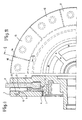
- a groove-like incision 12 is provided in the pressure flange 9, which is from the side of the clamping flange 3 extends towards the grinding wheel 11, but does not extend through the entire thickness of the pressure flange 9.
- incisions 14 extending to the outer circumference of the pressure flange 9 are provided, which run radially and by which the pressure flange 9 is divided into individual pressure flange sections, e.g. B. the pressure flange sections 15, 16, 17 and 18 shown in FIG.
- incisions 14 are not groove-like, but instead run through the entire thickness of the pressure flange 9, flap-like pressure flange sections 15, 16, 17 and 18 are created, which are connected to the rest of the pressure flange 9 in their foot region, but are in contact can move a certain amount individually.
Landscapes
- Engineering & Computer Science (AREA)
- Mechanical Engineering (AREA)
- Gripping On Spindles (AREA)
- Polishing Bodies And Polishing Tools (AREA)
- Constituent Portions Of Griding Lathes, Driving, Sensing And Control (AREA)
- Grinding Of Cylindrical And Plane Surfaces (AREA)
Description
- Die Erfindung bezieht sich auf eine hydraulische Spannmutter gemäß dem Oberbegriff des Hauptanspruches.
- Eine gattungsbildende hydraulische Spannmutter wird in der DE-PS 33 11 078 beschrieben. Bei dieser bekannten Einrichtung ist der eigentliche Druckflansch als umlaufende Ringscheibe ausgebildet, die zwischen die Kolben der hydraulischen Druckvorrichtung und die Schleifscheibe eingeschaltet ist. Diese Ringscheibe führt sich dabei in axialer Richtung frei gleitbar auf dem Spannbolzen.
- Bei großen Schleifscheiben ergibt sich das Problem, daß innerhalb der Schleifscheiben beim Brennen derselben Spannungen auftreten und daß die Oberflächen der Schleifscheiben nicht genau planparallel sind, so daß beim Einspannen derartiger unter Spannung stehender Schleifscheiben in die hydraulische Spannvorrichtung der eigentliche Druckflansch nicht überall gleichmäßig an der Schleifscheibenoberfläche anliegt. Durch die dann im Betrieb der Schleifscheibe auftretenden zusätzlichen Beanspruchungen kann es durch diese ungleichmäßige Einspannung der Schleifscheibe zu Rissen in der Schleifscheibe kommen, die die Schleifscheibe unbrauchbar machen.
- In der DE-A-27 32 271 wird eine Spannvorrichtung für Schleifscheiben beschrieben, die einen festen Aufnahmeflansch und einen Gegenflansch aufweist. Der Aufnahmeflansch ergibt eine steife und definierte Lage der Schleifscheibe. Der Gegenflansch wird mit Hilfe von Spannschrauben gegen den Aufnahmeflansch gezogen und legt sich unter Zwischenschaltung eines einteiligen, umlaufenden Zwischenringes an die Außenseite der Schleifscheibe an. In dem Gegenflansch sind Schlitze vorgesehen, die in Verbindung mit einer zusätzlichen Hinterdrehung eine hohe Nachgiebigkeit des Gegenflansches in axialer Richtung im äußeren Bereich schaffen sollen. Die Spannschrauben sind aber im festen inneren Bereich des Gegenflansches angeordnet und der Gegenflansch wird entsprechend dem vorgesehen Spannweg deformiert. Die Anpassung an Unebenheiten der Schleifscheibe erfolgt also durch die Steifigkeit bzw. Elastizität des Gegenflansches und durch Einpassung eines Paßringes zwischen Gegenflansch und Aufnahmeflansch. Die Einspannung der Schleifscheibe über ihren gesamten Umfang gesehen ist also noch nicht ideal.
- Der Erfindung liegt die Aufgabe zugrunde, die gattungsbildende hydraulische Spannmutter dahingehend zu verbessern, daß die Einspannung der Schleifscheibe durch die Spannmutter über den Umfang des Druckflansches gesehen gleichmäßig erfolgt.
- Diese der Erfindung zugrundeliegende Aufgabe wird durch die Lehre des Hauptanspruches gelöst.
- Mit anderen Worten ausgedrückt, schlägt die Erfindung vor, daß weiterhin der eigentliche Druckflansch einteilig ausgebildet ist, so daß dadurch seine Handhabung vereinfacht wird und nicht eine Vielzahl einzelner Segmente, die dann den Druckflansch bilden, auf den Spannbolzen aufgesetzt werden müssen. Andererseits wird durch den nutartigen, zur Rotationsachse konzentrischen Einschnitt und die radialen Einschnitte eine Auflösung des äußeren Umfangsbereiches des Druckflansches in Einzelsegmente erreicht, die etwas gegeneinander und unabhängig voneinander beweglich sind. Hierdurch können sich diese Segmente oder Druckflanschabschnitte der Form der Schleifscheibe besser anpassen.
- Dadurch, daß gemäß dem Merkmal des Anspruches 2 vorgeschlagen wird, daß jeder Druckflanschabschnitt von zwei Kolben der hydraulischen Druckvorrichtung beaufschlagt wird, erfolgt auch auf dem Druckflanschabschnitt eine gleichmäßige Belastung bzw. Druckbeaufschlagung desselben.
- Ein Ausführungsbeispiel der Erfindung wird nachfolgend anhand der Zeichnung erläutert. Die Zeichnung zeigt dabei in
- Fig. 1
- einen Schnitt durch einen Teil einer hydraulischen Spannmutter gemäß der Linie 1 - 1 in Fig. 2 und in
- Fig. 2
- eine Ansicht auf einen Teil einer hydraulischen Spannmutter.
- In den Zeichnungen ist mit 1 ein Spannbolzen bezeichnet, der eine Schleifscheibenaufnahme 2 bildet. Auf dem Spannbolzen ist ein Spannflansch 3 gelagert, der mit Innengewinde 4 auf das Außengewinde 5 des Spannbolzens 1 aufschraubbar ist. Der Spannflansch weist einen Druckmittelversorgungskanal 6 auf, der eine Vielzahl von Zylinderbohrungen 7 versorgt, in denen Kolben 8 individuell abgedichtet und beweglich gelagert sind, so daß durch die Kolben 8 eine hydraulische Druckvorrichtung geschaffen wird, die über den ganzen Umfang des Spannflansches 3 verteilt ist. Die Kolben 8 wirken auf einen Druckflansch 9, der axial beweglich auf einer entsprechenden Schulter 10 des Spannbolzens geführt ist. Zwischen dem Druckflansch 9 und der Schleifscheibenaufnahme 2 ist eine Schleifscheibe 11 eingespannt, wobei die Flächen der Schleifscheibenaufnahme 2 und des Druckflansches 9, die zur Schleifscheibe 11 hin gerichtet sind, aufgerauht ausgebildet sind, um damit die Schleifscheibe besser zu halten.
- Konzentrisch zur Rotationsachse und zum Spannbolzen 1 ist in dem Druckflansch 9 ein nutartiger Einschnitt 12 vorgesehen, der von der Seite des Spannflansches 3 aus sich zur Schleifscheibe 11 hin erstreckt, aber nicht die ganze Stärke des Druckflansches 9 durchgreift. Wie aus Fig. 2 ersichtlich, sind - ausgehend von dem nutartigen Einschnitt 12 -sich zum Außenumfang des Druckflansches 9 erstreckende Einschnitte 14 vorgesehen, die radial verlaufen und durch die der Druckflansch 9 in einzelne Druckflanschabschnitte unterteilt wird, z. B. die aus Fig. 2 ersichtlichen Druckflanschabschnitte 15, 16, 17 und 18.
- Weiterhin ist aus Fig. 2 erkennbar, daß auf jeden so gebildeten Druckflanschabschnitt 15 bis 18 zwei Kolben 8 einwirken, so daß eine gleichmäßige Belastung jedes Druckflanschabschnittes erreicht wird.
- Dadurch, daß die Einschnitte 14 nicht nutartig ausgebildet sind, sondern durch die ganze Stärke des Druckflansches 9 verlaufen, werden lappenartige Druckflanschabschnitte 15, 16, 17 und 18 geschaffen, die in ihrem Fußbereich mit dem Rest des Druckflansches 9 in Verbindung stehen, aber sich um ein gewisses Maß individuell bewegen können.
Claims (2)
- Hydraulische Spannmutter für umlaufende Werkzeuge (11), insbesondere Schleifscheiben, mit einem ringförmigen Spannflansch (3), der mittels Innengewinde (4) auf einem Spannbolzen (1) einer Spannvorrichtung aufschraubbar ist und mehrere, mit einem Druckmittelversorgungskanal (6) in Verbindung stehende Zylinderbohrungen parallel und konzentrisch zur Rotationsachse aufweist, in denen eine entsprechende Anzahl von Kolben (8) einzeln abgedichtet und axial beweglich jeweils als hydraulische Druckstempel wirkend geführt sind, wobei die Kolben (8) auf einen am Werkzeug (11) anliegenden ringförmigen, auf dem Spannbolzen (1) in axialer Richtung beweglich gelagerten Druckflansch (9) wirken und sich das Werkzeug (11) an der dem Druckflansch gegenüberliegenden Seite an einer Stirnfläche einer Schleifscheibenaufnahme (2) abstützt, dadurch gekennzeichnet, daß der Druckflansch (9) aus einem Ringfuß besteht, an dessen zur Rotationsachse konzentrischen, den Ringfuß nur teilweise durchquerenden nutartigen Einschnitt (12) sich einzelne durch radiale, von dem nutartigen Einschnitt (12) bis zum Außenumfang verlaufende, sich durch die ganze Stärke des Druckflansches erstreckende Einschnitte (14) gebildete Druckflanschabschnitte (15) anschliessen, auf die die Kolben (8) wirken.
- Hydraulische Spannmutter nach Anspruch 1, dadurch gekennzeichnet, daß auf jeden einzelnen Druckflanschabschnitt zwei Kolben (8) der hydraulischen Druckvorrichtung einwirken.
Priority Applications (4)
| Application Number | Priority Date | Filing Date | Title |
|---|---|---|---|
| EP87116396A EP0314833B1 (de) | 1987-11-06 | 1987-11-06 | Hydraulische Spannmutter für umlaufende Werkzeuge, insbesondere Schleifscheiben |
| AT87116396T ATE66847T1 (de) | 1987-11-06 | 1987-11-06 | Hydraulische spannmutter fuer umlaufende werkzeuge, insbesondere schleifscheiben. |
| ES87116396T ES2025126B3 (es) | 1987-11-06 | 1987-11-06 | Tuerca de tension hidraulica para herramientas circulantes, especialmente muelas abrasivas |
| DE8787116396T DE3772770D1 (de) | 1987-11-06 | 1987-11-06 | Hydraulische spannmutter fuer umlaufende werkzeuge, insbesondere schleifscheiben. |
Applications Claiming Priority (1)
| Application Number | Priority Date | Filing Date | Title |
|---|---|---|---|
| EP87116396A EP0314833B1 (de) | 1987-11-06 | 1987-11-06 | Hydraulische Spannmutter für umlaufende Werkzeuge, insbesondere Schleifscheiben |
Publications (2)
| Publication Number | Publication Date |
|---|---|
| EP0314833A1 EP0314833A1 (de) | 1989-05-10 |
| EP0314833B1 true EP0314833B1 (de) | 1991-09-04 |
Family
ID=8197426
Family Applications (1)
| Application Number | Title | Priority Date | Filing Date |
|---|---|---|---|
| EP87116396A Expired - Lifetime EP0314833B1 (de) | 1987-11-06 | 1987-11-06 | Hydraulische Spannmutter für umlaufende Werkzeuge, insbesondere Schleifscheiben |
Country Status (4)
| Country | Link |
|---|---|
| EP (1) | EP0314833B1 (de) |
| AT (1) | ATE66847T1 (de) |
| DE (1) | DE3772770D1 (de) |
| ES (1) | ES2025126B3 (de) |
Family Cites Families (3)
| Publication number | Priority date | Publication date | Assignee | Title |
|---|---|---|---|---|
| GB838511A (en) * | 1956-04-19 | 1960-06-22 | Rawdon Engineering & Tool Co L | Improvements relating to the securing of slitting saws and other cutting tools to their holders or supports |
| DE2732271A1 (de) * | 1977-07-16 | 1979-01-25 | Salje Ernst | Spannvorrichtung fuer schleifscheiben |
| DE3311078C2 (de) * | 1982-03-27 | 1986-02-20 | Klaus-Dieter 2800 Bremen Grützmacher | Hydraulische Spannmutter |
-
1987
- 1987-11-06 DE DE8787116396T patent/DE3772770D1/de not_active Expired - Fee Related
- 1987-11-06 AT AT87116396T patent/ATE66847T1/de not_active IP Right Cessation
- 1987-11-06 EP EP87116396A patent/EP0314833B1/de not_active Expired - Lifetime
- 1987-11-06 ES ES87116396T patent/ES2025126B3/es not_active Expired - Lifetime
Also Published As
| Publication number | Publication date |
|---|---|
| DE3772770D1 (de) | 1991-10-10 |
| ES2025126B3 (es) | 1992-03-16 |
| ATE66847T1 (de) | 1991-09-15 |
| EP0314833A1 (de) | 1989-05-10 |
Similar Documents
| Publication | Publication Date | Title |
|---|---|---|
| DE1216654B (de) | Zentrierende Spanneinrichtung | |
| DE1919269B1 (de) | Siebwechseleinrichtung fuer einen Extruder | |
| DE102020205721A1 (de) | Ladeteller für Federendenschleifmaschine und Federendenschleifmaschine | |
| EP0925163B1 (de) | Vorrichtung zum entgraten von werkstücken, insbesondere formteilen und giessteilen aus kunststoff, gummi oder dgl. | |
| EP0943396B1 (de) | Spanneinrichtung zur Fixierung einer mit einem Einzugsnippel versehenen Palette an einer Aufspannplatte | |
| EP0020864B1 (de) | Werkzeugaufnahme, insbesondere für das Werkzeug einer Wälzfräsmaschine | |
| EP0630721A1 (de) | Hydraulisches Spannelement | |
| EP0314833A1 (de) | Hydraulische Spannmutter für umlaufende Werkzeuge, insbesondere Schleifscheiben | |
| DE861650C (de) | Vorrichtung zum Spannen von Drahtspeichenraedern | |
| DE3637747C1 (en) | Hydraulic clamping nut for rotating tools, in particular grinding wheels | |
| DE4430535A1 (de) | Vorrichtung zur axialen Montage eines Nabenbauteils auf einer Welle | |
| DE1961424A1 (de) | Hydraulische Vorrichtung zum Anziehen eines Bolzens | |
| DE4041683A1 (de) | Hydraulisches spannelement | |
| EP3570704B1 (de) | Werkzeug zur bearbeitung von oberflächen, kantenbereichen und konturen | |
| DE2551762A1 (de) | Spannvorrichtung fuer laeppmaschinen zur ausrichtung und begrenzung der laepparbeit | |
| DE2512227A1 (de) | Spreizdorn | |
| DE102019124418A1 (de) | Wuchtadapter für eine Wuchtvorrichtung | |
| DE1120841B (de) | Vorrichtung zum Zentrieren von Drehkoerpern auf Aufnahmedornen | |
| DE2619190C3 (de) | Senkrechter Mehrspindel-Futter-Drehautomat | |
| EP0219599A1 (de) | Pinolenführung für Werkzeugmaschinen, insbesondere Drehmaschinen | |
| DE2162293C3 (de) | Futter zum Festspannen eines Tellerzahnrades | |
| DE3620526A1 (de) | Revolverkopf | |
| DE1948126A1 (de) | Werkstueckspender | |
| DE7810680U1 (de) | Spanndorn | |
| DE495690C (de) | Kraftwagenrad |
Legal Events
| Date | Code | Title | Description |
|---|---|---|---|
| PUAI | Public reference made under article 153(3) epc to a published international application that has entered the european phase |
Free format text: ORIGINAL CODE: 0009012 |
|
| 17P | Request for examination filed |
Effective date: 19880408 |
|
| AK | Designated contracting states |
Kind code of ref document: A1 Designated state(s): AT BE CH DE ES FR GB IT LI NL SE |
|
| 17Q | First examination report despatched |
Effective date: 19900702 |
|
| GRAA | (expected) grant |
Free format text: ORIGINAL CODE: 0009210 |
|
| AK | Designated contracting states |
Kind code of ref document: B1 Designated state(s): AT BE CH DE ES FR GB IT LI NL SE |
|
| PG25 | Lapsed in a contracting state [announced via postgrant information from national office to epo] |
Ref country code: SE Effective date: 19910904 Ref country code: NL Effective date: 19910904 Ref country code: BE Effective date: 19910904 |
|
| REF | Corresponds to: |
Ref document number: 66847 Country of ref document: AT Date of ref document: 19910915 Kind code of ref document: T |
|
| REF | Corresponds to: |
Ref document number: 3772770 Country of ref document: DE Date of ref document: 19911010 |
|
| ET | Fr: translation filed | ||
| PG25 | Lapsed in a contracting state [announced via postgrant information from national office to epo] |
Ref country code: AT Effective date: 19911106 |
|
| PG25 | Lapsed in a contracting state [announced via postgrant information from national office to epo] |
Ref country code: LI Effective date: 19911130 Ref country code: CH Effective date: 19911130 |
|
| ITF | It: translation for a ep patent filed | ||
| GBT | Gb: translation of ep patent filed (gb section 77(6)(a)/1977) | ||
| NLV1 | Nl: lapsed or annulled due to failure to fulfill the requirements of art. 29p and 29m of the patents act | ||
| REG | Reference to a national code |
Ref country code: ES Ref legal event code: FG2A Ref document number: 2025126 Country of ref document: ES Kind code of ref document: B3 |
|
| PLBE | No opposition filed within time limit |
Free format text: ORIGINAL CODE: 0009261 |
|
| STAA | Information on the status of an ep patent application or granted ep patent |
Free format text: STATUS: NO OPPOSITION FILED WITHIN TIME LIMIT |
|
| REG | Reference to a national code |
Ref country code: CH Ref legal event code: PL |
|
| 26N | No opposition filed | ||
| PGFP | Annual fee paid to national office [announced via postgrant information from national office to epo] |
Ref country code: DE Payment date: 19920910 Year of fee payment: 6 |
|
| PGFP | Annual fee paid to national office [announced via postgrant information from national office to epo] |
Ref country code: ES Payment date: 19921007 Year of fee payment: 6 |
|
| PGFP | Annual fee paid to national office [announced via postgrant information from national office to epo] |
Ref country code: FR Payment date: 19921028 Year of fee payment: 6 |
|
| PGFP | Annual fee paid to national office [announced via postgrant information from national office to epo] |
Ref country code: GB Payment date: 19921102 Year of fee payment: 6 |
|
| PG25 | Lapsed in a contracting state [announced via postgrant information from national office to epo] |
Ref country code: GB Effective date: 19931106 |
|
| PG25 | Lapsed in a contracting state [announced via postgrant information from national office to epo] |
Ref country code: ES Free format text: LAPSE BECAUSE OF EXPIRATION OF PROTECTION Effective date: 19931108 |
|
| GBPC | Gb: european patent ceased through non-payment of renewal fee |
Effective date: 19931106 |
|
| PG25 | Lapsed in a contracting state [announced via postgrant information from national office to epo] |
Ref country code: FR Effective date: 19940729 |
|
| PG25 | Lapsed in a contracting state [announced via postgrant information from national office to epo] |
Ref country code: DE Effective date: 19940802 |
|
| REG | Reference to a national code |
Ref country code: FR Ref legal event code: ST |
|
| REG | Reference to a national code |
Ref country code: ES Ref legal event code: FD2A Effective date: 20010301 |
|
| PG25 | Lapsed in a contracting state [announced via postgrant information from national office to epo] |
Ref country code: IT Free format text: LAPSE BECAUSE OF NON-PAYMENT OF DUE FEES;WARNING: LAPSES OF ITALIAN PATENTS WITH EFFECTIVE DATE BEFORE 2007 MAY HAVE OCCURRED AT ANY TIME BEFORE 2007. THE CORRECT EFFECTIVE DATE MAY BE DIFFERENT FROM THE ONE RECORDED. Effective date: 20051106 |