EP0314115B1 - Method and system for generating free curved surface - Google Patents
Method and system for generating free curved surface Download PDFInfo
- Publication number
- EP0314115B1 EP0314115B1 EP88117864A EP88117864A EP0314115B1 EP 0314115 B1 EP0314115 B1 EP 0314115B1 EP 88117864 A EP88117864 A EP 88117864A EP 88117864 A EP88117864 A EP 88117864A EP 0314115 B1 EP0314115 B1 EP 0314115B1
- Authority
- EP
- European Patent Office
- Prior art keywords
- cross sectional
- coordinate system
- curve
- generating
- curved surface
- Prior art date
- Legal status (The legal status is an assumption and is not a legal conclusion. Google has not performed a legal analysis and makes no representation as to the accuracy of the status listed.)
- Expired - Lifetime
Links
Images


Classifications
-
- G—PHYSICS
- G06—COMPUTING; CALCULATING OR COUNTING
- G06T—IMAGE DATA PROCESSING OR GENERATION, IN GENERAL
- G06T11/00—2D [Two Dimensional] image generation
- G06T11/20—Drawing from basic elements, e.g. lines or circles
-
- G—PHYSICS
- G06—COMPUTING; CALCULATING OR COUNTING
- G06T—IMAGE DATA PROCESSING OR GENERATION, IN GENERAL
- G06T17/00—Three dimensional [3D] modelling, e.g. data description of 3D objects
- G06T17/20—Finite element generation, e.g. wire-frame surface description, tesselation
Definitions
- the present invention relates to a system and method for generating a free curved surface and specifically relates to the free curved surface generating system and method which facilitate a correction of the free curved surface.
- a plurality of cross sectioned curves indicating cross sectional shape at a plurality of arbitrary positions of the solid of figure to be generated are generated in an x-y coordinate system, these cross sectional curves are arranged at desired positions in an x-y-z coordinate system, respectively, curved surface are formed between these cross sectional curves through interpolations, and data representing the solid of figure constituted by the free curved surfaces are prepared.
- the above-described objects can be achieved by providing the system and method for generating the free curved surface in which a plurality of cross sectional curves representing the cross sectional shape in an x-y coordinate system are prepared and when the plurality of cross sectional curves are parallel translated and rotated in an x-y-z coordinate system, the data on parallel translations and rotations for the respective cross sectional curves are stored in corresponding storage areas of a memory and thereafter the respective cross sectional curves are rotated and translated on the basis of the stored data on rotations and parallel translations when a coordiate transformation between the x-y coordiate system and x-y-z coordinate system is carried out for the same cross sectional curves.
- Fig. 1 is a schematic block diagram representing a preferred embodiment of a system for generating a free curved surface according to the present invention.
- Fig. 2 is a schematic diagram representing generation of a cross sectional curve in an x-y coordinate system.
- Fig. 3 is a schematic diagram representing a state in which a plurality of cross sectional curves are arranged at desired position in an x-y-z coordinate system.
- Fig. 4 is a schematic diagram representing a state in which a basic outline is formed in the x-y coordinate system in the free curved surface in the system and method for generating the free curved surface according to the present invention.
- Fig. 5 is a schematic diagram representing a x-y coordinate state in which one cross sectional curve is generated on the basis of the basic outline in the system and method for generating the free curved surface according to the present invention.
- Fig. 6 is a schematic diagram representing an x-y coordinate state in which a curve segment is generated on the basis of positions of a plurality of control points in the system and method for generating the free curved surface according to the present invention.
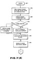
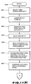
- Figs. 7 (A) and 7 (B) are integrally a flowchart for explaining a procedure for generating one cross sectional curve from the basic outline in the system and method for generating the free curved surface according to the present invention.
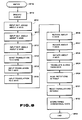
- Fig. 8 is a flowchart for explaining a procedure for arranging one cross sectional curve at a desired position in the x-y-z coordiate system.
- Fig. 9 is a schematic diagram for explaining memory locations in which data on each cross sectional curve is stored in a memory shown in Fig. 1 of the system and method for generating the free curved surface according to the present invention.
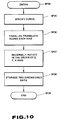
- Fig. 10 is a flowchart for explaining a procedure for transferring one cross sectional curve arranged from the x-y-z coordinate system into the x-y coordiate system in the system and method for generating the free curved surface according to the present invention.
- Figs. 11 (A) and 11 (B) are integrally a flowchart for explaining a procedure for transforming one cross sectional curve representing the cross sectional shape of the free curved surface cut at the desired postion to an x-y plane in the system and method for generating the free curved surface according to the present inevntion.
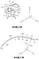
- Fig. 12 is a schematic diagram representing an x-y coordinate state in which the free surface is cut at the desired position in the system and method for generating the free curved surface according to the present invention.
- Fig. 13 is a schematic diagram representing an x-y-z coordinate state in which one curve is generated on the basis of positions of a plurality of control points.
- Fig. 14 is a schematic diagram representing an x-y-z coordinate state in which a reference point of the cross sectional curve representing the cross sectional shape when the free curved surface is cut at the desired position is matched with an origin of the x-y-z coordinate system in the system and method for generating the free curved surface according to the present invention.
- Fig. 15 is a schematic diagram for explaining a method for determining rotations of the cross sectional curve representing the cross sectional profile when the free curved surface is cut at the desired position which is transformed into the x-y plane.
- Fig. 16 is a schematic diagram representing an x-y-z coordinate state in which the cross sectional curve representing the cross sectional profile when the free curved surface is cut at the desired position is transferred into the x-y plane in the system and method for generating the frre curved surface according to the present invention.
- Fig. 17 is a schematic diagram representing an x-y-z coordinate state in which the cross sectional curve in the x-y plane is transferred to an original position in the x-y-z coordinate system in the system and method for generating the free curved surface according to the present invention.
- Fig. 1 shows a preferred embodiment of a system for generating a free curved surface according to the present invention.
- the free curved surface generating system is generally denoted by 1 and includes an input unit 2 (for example, keyboard) for inputting various data and instructions to be described later, an arithmetic operation processing unit 4 for generating cross sectional curves and free curved surfaces on the basis of the data inputted from the input unit 2 , and a display unit 3 for displaying the generated cross sectional curves and free curved surface to be described later.
- an input unit 2 for example, keyboard
- an arithmetic operation processing unit 4 for generating cross sectional curves and free curved surfaces on the basis of the data inputted from the input unit 2
- a display unit 3 for displaying the generated cross sectional curves and free curved surface to be described later.
- the arithmetic operation processing unit 4 functionally includes: basic outline generating unit (first means) 4 a for generating the basic outline which serves as a basic outline when one cross sectional curve is generated, cross sectional curves generating unit (second means) 4 b for generating each of cross sectional curves in the x-y coordinate system on the basis of the basic outline; coordinate transforming unit (third means) 4 c for carrying out a transformation of the cross sectional curves between the x-y coordinate (two dimensional space) system and an x-y-z coordinate (three dimensional space) system on the basis of set rotations and parallel translations; interpolation unit (fourth means) 4 d for interpolating curved surfaces between the plurality of cross sectional curves which have been transformed from the x-y coordinate system to the x-y-z coordinate system to form the free curved surface; cut curved surface generating unit (fifth means) 4 e for generating cut curves through the cut of the cross sectional curves at an aribitrary position
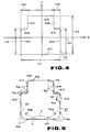
- a basic outline K1 of a polygon is specified having an outer dimension of L x2 in the x axis direction, and an outer dimension of L y2 in the y axis direction, and each line segment thereof being formed in a straight line.
- the basic outline K1 in the preferred embodiment is such that a left-side line segment K12 and a right-side line segment K13 are extended having a length of L y21 and a length of L y22 in the y axis direction from left and right ends of a lower-side line segment K11 extended in the x axis direction, cut-in line segments K14 and K15 are extended inwardly from respective upper ends of the line segments K12, K13 having lengthes L x21 and L x23 and cut-in line segments K17, K18 are extended from inner ends of the line segments K14, K15 straightly upward to upper-side line segments K17, K18 .
- a designer specifies a rough sketch of the outer shape as a polygon-formed basic outline K1 described above and thereafter inputs radius information corresponding to each corner present on the basic outline K1 required to generate the cross sectional curve S c on the basis of each line segment constituting the basic outline K1 to the cross sectional curves generating unit 4 b in Fig. 1 , thus generating a desired cross sectional curve ( denoted by a solid line of Fig. 5 ) based on the basic outline K1 . This is carried out via the input unit 2 .
- a curve segment K SG in an arc form generated at each corner of the basic outline K1 is generated by means of a Bezier curve representing a parametric free curve.
- a curve segment K SG is generated between two deforming control points P DM by setting a plurality of deforming control points P DM on the basic outline K1 , as shown in Fig. 5 .
- each curve segment K SG is expressed as follows, supposing that one deforming control point P DM is a reference control point P o .
- R (t) (1 - t + t E) 3 P o R (t) : a positional vector indicating the corresponding curve segment K SG .
- t in a case where the other deforming control point P DM is another reference control point P 3 , t denotes a parameter changing from 0 to 1 between a distance from the reference control point P o to the other reference control point P 3 ( 0 ⁇ t ⁇ 1 ).
- E denotes a shift operator and the following relationship is established by a setting of control points P 1 and P 2 between the two reference point P o and P 3 :
- all curve segments K SG can be represented by four control points P 0 , P 1 , P 2 and P 3 on the basis of the equation (3). This means that if two control points P 1 and P 2 are selected at aribitrary positions located between the two reference points P o and P 3 according to thire necessities on the basic outline K1 , the shape of the curve segment K SG can accordingly be locally set as an aribitary free curve.
- a pair of the reference points P 0 and P 3 which determine a dimensional range of the curve segment K SG is specified so that a curve inscribing the basic outline K1 can practically be generated.
- the designer can design a desired form in a range of the outer dimension predetermined as a design requirement.
- the free curved surface generating system according to the present invention can easily generate the curved segment even if the curve segment is formed having an acute corner between the adjacent curve segments K SG (for example, in a case where an arc having an extremely different radius from the curve segment is adjoined).
- the basic outline generating unit 4 a and cross sectional curve generating unit 4 b shown in Fig. 1 generate the cross sectional shape on the basis of the above-described cross sectional shape generating method in accordance with a processing routine shown in Figs. 7 ( A ) and 7 ( B ).
- a step SP 1 the routine enters the cross sectional shape generating processing program, the basic outline generating unit 4 a waites for inputting the data basic outline K1 in the form of polygon of cross section by the designer through the input unit 2 in a step SP 2 .
- the designer inputs the coordinate data of apexes present at both ends of each line segment forming the basic outline K1 as described above with reference to Fig. 4 so as to enable input of the rough sketch of cross section in the polygonal shape.
- the routine Upon completion of the data input, in the free curved surface generating system 1 , the routine goes to a step SP 3 in which the outer shape formed by linking the apexes inputted with the respective line segments K11 to K18 is displayed on the display unit 3 and the routine goes to a step SP 4 .
- the cross sectional curve generating unit 4 b in Fig. 1 waites for receiving an instruction indicating whether a deformed curve K2 having the same radius as that at each corner should be specified at a corner located at each apex position of the basic outline K1 and the designer inputs the instruction indicating an ackowledgement (Yes) or negative acknowledgement (No) via the input unit 2 to the cross sectional curve generating unit 4 b on the basis of a designer's design feeling.
- the routine goes to a step SP 5 in which the unit 4 b waites for receiving radius data to be applied to all corners from the designer via the input unit 2 and goes to a step SP 6 when the specified radius data is inputted.
- the routine goes to a step SP 7 in which the unit 4 b waites for receiving and specifying the corresponding radius data for each corner from the designer via the input unit 2 and the routine goes to the step SP 6 when the specification of radius data is ended.
- the basic outline line segments K16, K18 are parallel translated in an arrow-marked A direction and arrow-marked B direction by a distance equal to the radius r of the curve segment K SG to be generated and an intersection of the parallel translated basic outline segments K16, K18 is an origin 0 of the x-y coordinate system.
- control points P 1 , P 2 are provisionally set on a line segment extended toward an intersection D of the basic outline K 16 and the basic outline K 18 from the reference control points P 0 , P 3 and distances from the reference control point P 0 to the control point P 1 and from the reference control point P 3 to the control point P 3 are equally denoted by a .
- the distance between the reference control point P 0 and control point P 1 and the distance between the reference control point P 3 and control point P 2 are determined from the equation (10) by the angle between a vector having a length of the radius r of the curve segment K SG to be generated and directing from the origin 0 to the intersection D and a vector directing from the origin 0 to the reference control point P 0 .
- the cross sectional curve generating unit 4 b generates the cross sectional curve data constituting data on the curve segment K SG calculated for the corresponding corner and the data on straight line portion inputted as the basic outline K1 .
- the routine goes to a next step SP 8 in which the data derived in the step SP 7 is displayed on the display unit 3 as the cross sectional shape data.
- the designer can visually inspect the cross sectional shape formed so as to inscribe the basic outline K1 through the display screen of the unit 3 .
- the designer thus, designs step by step the cross sectional outer shape toward an exactly desired form by repeatedly inputting processed data for correcting partially the outer shape displayed on the screen of the display unit 3 .
- the cross sectional curve generating unit 4 b waits for determining whether the designer corrects the undeformed straight portion from among the straight line portions of the basic outline K1 (not deformed by the above-described steps till step SP 7 ) and the routine goes to a step SP 10 when the disigner inputs via the input unit 2 a correction instruction to correct the undeformed straight line portion.
- the designer inputs the position data of the straight line portion to be corrected and then inputs the correction data to deform the straight line portion to an arc shape.
- the contents of correction is such that the deforming control point P DM placed on both ends of the straight line portion ⁇ on the basic outline K1 is set as reference control points P 0 and P 3 and the positions of, for example, four control points are specified between the reference control points P 0 and P 3 so that the straight line portion ⁇ is modified to a predetermined arc portion as denoted by a dot line in Fig. 5 .
- the cross sectional curve generating unit 4 b When the input of data is ended in the step SP 10 , the cross sectional curve generating unit 4 b generates the curve data in place of the straight line portion data on the basis of the positions of the reference control points P 0 and P 3 and control points P 1 and P 2 in the step SP 11 using the equation (3) and thereafter the cross sectional shape including data generated in the step SP 12 is displayed on the display unit 3 .
- the designer can visually inspect the cross sectional outer form having the straight line portion corrected to the arc shape, the basic outline K1 not deformed and arc-formed curve segment K SG generated at the corner.
- the series of processings described above is a processing routine in a case where the corrected portion is present at the straight line portion in the above-described step SP 9 .
- the cross sectional curve generating unit 4 b is immediately transferred to a step SP 13 in which the unit 4 b determines if another portion of the basic outline K1 should be corrected.
- the routine goes to a step SP 14 in which the portion to be further corrected is specified other than the straight line portion and the unit 4 b waites for the input of the data on the corrected portion now processed.
- step SP 14 When the input of the corrected data is ended in the step SP 14 , the correction processing for the cross sectional curve is executed on the basis of the data to be inputted in a step SP 15 . Thereafter, the routine goes to the next step SP 16 in which the corrected cross sectional curve is displayed on the display unit 3 and thereafter the routine returns to the step SP 9 described above.
- the disigner can finally view the cross sectional curve by generating the curve segment inscribing the corner portion of the basic outline K1 on the basis of the data of the basic outline K1 .
- the designer can previously specify the finished dimension of the cross sectional outer shape after end of the design before the designer's designing operation is started.
- the design operation of the cross sectional shape can more remarkably be facilitated.
- the designing operation can be carried out such that the repetitions of correcting designed cross sectional shape are continued stepwise to approach to the desired profile.
- the shape of the curve segment K SG can aribitrarily be set to a free curve according to the designer's requirement by inputting data on aribitrary control points P 1 and P 2 in place of the radius data.
- the plurality of line segments extended in the x axis direction and y axis direction are used to constitute the basic outline K1
- the direction toward which each line segment is extended is not limited but an aribitrary line segment extended in an oblique direction with respect to the x or y axis direction may be used.
- an arbitrary curve not limited to the straight line may be used to constitute the basic outline K1 .
- the deforming control points P DMX may be specified at positions not on the basic outline K1 but between the deforming control points P DM . Then, the curve segment may be generated between these deforming control points P DM and P DMX , respectively. In this case, the same effects as those described above can be achieved.
- the designer through the arithmetic operation processing unit 4 specifies (selects) a desired cross sectional curve S C1 from among a plurality of cross sectional curves S Ci generated in the procedure described above in a step SP 19 , after the start of the routine shown in Fig. 8 in a step SP 18 .
- arithmetic operation processing unit 4 receives rotations (also called an angular displacement or rotation quantity) through which the cross sectional curve S C1 is rotated with the x axis as a center of rotation.
- step SP 21 the rotations with the y axis as a center of rotation is inputted and in the next step SP 22 , the rotations with the z axis as the center of rotation is inputted.
- a gradient of the cross sectional curve S C required for the designer when the cross sectional curve S C is arranged in the x-y-z coordinate system can be specified as the rotations with the x axis, y axis, and z axis as the respective centers of rotations.
- the arithmetic operation processing unit 4 receives parallel translations (also called a parallel translation quantity) in the x axis direction in a step SP 23 , those in the y axis direction in a step SP 24 , and those in the z axis direction in a step SP 25 .
- the parallel translations from the original position to the arranged position required for the designer when the cross sectional curve S C is arranged in the x-y-z coordinate system are specified separating into coordinate components in the x axis, y axis, and z axis directions.
- the coordinate transformation unit 4 c rotates the control points constituting the cross sectional curve S C through the rotations inputted in the step SP 20 .
- Each curve segment K SG constituting the cross sectional curve S C can be represented by the four control points as expressed by the equation (1) so that the control points thereof are moved to enable the movement of the cross sectional curve.
- a step SP 27 the coordinate transformation unit 4 c rotates the control points P 0 to P 3 through the rotations inputted in the step SP 21 with the y axis as the center of rotation, the control points P 0 to P 3 being rotated with the x axis as the center of rotation.
- a step SP 28 the coordinate transformation unit 4 c rotates the control points P 0 to P 3 through the rotations inputted in the step SP 22 with the z axis as the center of rotation, the control points being rotated with the y axis as the center of rotation.
- the control points P 0 to P 3 can be rotated on the basis of the rotations data inputted in the steps SP 20 - SP 21 - SP 22 and if the cross sectional curve S C is constructed by the cross sectional curve generating unit 4 b on the basis of the control points P 0 to P 3 , the cross sectional curve S C inclined with respect to the origin 0 through the angle required for the designer when the cross sectional curve is arranged in the x-y-z coordinate system.
- a step SP 29 the coordinate transformation unit 4 c translates parallel the control points P 0 to P 3 which have been rotated in the x, y and z axis directions, respectively, on the basis of the parallel translations inputted in the steps SP 23 - SP 24 - SP 25 .
- the respective control points P 0 to P 3 are arranged at predetermined positions of the x-y-z coordinate system after the parallel translations upon end of the rotations and the cross sectional curve generating unit 4 b generates the cross sectional curve on the basis of the control points P 0 to P 3 so that the cross sectional curve can be arranged at the desired position in the x-y-z coordinate system required for the designer.
- the arithmetic operation processing unit 4 stores the input data and calculated data used in the series of processings into the memory 4 g in the steps SP 30, SP 31, and SP 32 .
- the head address of the segment data D xy corresponding to each cross sectional curve S C1 , S C2 , and S C3 and the data representing the number of the segment data are stored into a segment data head address storage area 6 and data storage area 7 for the number of segment data of the memory 4 g , respectively, as shown in Fig. 9 .
- the head address of the storage area storing the segment data D xy of the curve segment constituting each cross sectional curve S C1 , S C2 and S C3 and the number of the segment data can be determined.
- the rotations derived in the steps SP 20 - SP 21 - SP 22 are stored in a rotation storage area 8 for each of x axis, y axis, and z axis components and the parallel translations derived in the steps SP 23 - SP 24 - SP 25 are stored into a parallel translation storage area 9 for each of x axis, y axis, and z axis components.
- the movement data required when the cross sectional curve generated in the x-y coordinate system is rearranged in the x-y-z coodinate system can be recorded.
- the segment data of each curve segment K SG constituting the corresponding cross sectional curve S C1 , S C2 , and S C3 are expressed by two expression forms of the segment data D xy derived in the x-y coordinate system when the cross sectiona curves S C1 , S C2 , and S C3 are formed in the x-y coordinate system and of the segment data D xyz derived in the x-y-z coordinate system and when the curves S C1 , S C2 , and S C3 are rearranged in the x-y-z coordinate system, the segment data D xyz are stored in a segment data storage area 10 in the x-y-z coordinate system as shown in Fig. 9 .
- control point data of three, two, and five curve segments as the segment data D xy and D xyz constituting the cross sectional curves S C1 , S C2 , and S C3 are stored into the segment data storage area 5 in the x-y coodinate system and the segment data storage area 10 in the x-y-z coordinate system.
- the arithmetic operation processing unit 4 forms the cross sectional curve in the x-y-z coordinate system on the basis of the segment data D xyz in the x-y-z coordinate system through the cross sectional curve generating unit 4 b and displays the formed cross sectional curve on the display unit 3 .
- the interpolation unit 4 d shown in Fig. 1 carries out the interpolation calculation to place a curve patch to derive the outer shape of a product represented by a three-dimensional free curved surface.
- the predetermined cross sectional curve S C is corrected so that the segment data D XY in the x-y coordinate system constituting the cross sectional curve S C to be corrected is loaded to correct the segment data D xy in a case where the outer profile of the free curved surface in the x-y-z coordinate system is corrected.
- the corrected segment data D xy is transformed into the segment data D xyz in the x-y-z coordinate system and stored into the segment data storage area 10 in the x-y-z coordinate system on the basis of the data stored in the parallel translations and rotations storage areas 9 and 8 .
- the corrected segment data D xyz in the x-y-z coordinate system can directly be derived.
- the cross sectional shape of the corrected free curve can easily be derived in the x-y coordinate system.
- the routine executed in the arithmetic operation processing unit 4 goes from a step SP 34 to a step SP 35 in which the cross sectional curve S C is specified and the controlling unit 4 h is loaded with the segment data D XYZ in the x-y-z coordinate system of the cross sectional curve, parallel translations, and rotations from the memory 4 g and supplies them into the coordinate transformation unit 4 c .
- the routine goes to a step SP 36 in which the coordinate transforming unit 4 c carries out the parallel translations for the segment data D XYZ in the x-y-z coordinate system on the basis of data representing the supplied parallel translations. Then, the routine goes to a step SP 37 in which the cross sectional curve is rotated on the basis of the data representing the supplied rotations.
- a step SP 38 the segment data derived as the result of parallel translations and rotational translations are stored as the segment data D xy in the x-y coordinate system into the segment data storage area 5 in the x-y coordinate system and the routine goes to a step SP 39 and the routine is ended.
- the segment data D xy in the x-y coordinate system is derived representing the cross sectional form of the free surface corrected in the x-y-z coordinate system and the cross sectional curve generating unit 4 b forms the cross sectional curve S C on the basis of the segment data D XY in the x-y-z coordinate system and then outputs the curve S C to the display unit 3 to visually inspect the cross sectional shape of the corrected free curve.
- segment data D xy in the x-y coordinate system and the segment data D xyz in the x-y-z coordinate system are provided for each cross sectional curve, in the present invention either one of these segment data may be prepared according to their necessities.
- the segment data D xy in the x-y coordinate system is formed and corrected on the basis of the segment data D xyz in the x-y-z coordinate system. Thereafter, the corrected segment data D xy is transformed into the segment data D xyz in the x-y-z coordinate system.
- the free curve constituted by the cross sectional curve using the vector function represented by the Bézier equation is expressed
- the present invention can be applied to the free curve which may be expressed using another vector function such as a B-spline equation.
- cross sectional curve S C is expressed by the curve
- the present invention can be applied to an end portion of a product at which the free curve is formed.
- the arithmetic operation processing unit 4 starts the routine in a step SP 40 and receives a specification of the free curved surface F to derive the cross section in the x-y-z coordinate sytstem according to the input operationof the input unit 2 by the designer and thereafter the routine goes to the step SP 42 to generate a cut plane F p through which the free curved surface F is cut as shown in Fig. 12 .
- the cut plane F p is generated by the designer's inputting a desired one point in the x-y-z coordinate system and a direction from the point, desired two points in the x-y-z coordinate system, and desired three points in the x-y-z coordinate system into the cut curve generating unit 4 e of the arithmetic operation processing unit 4 of Fig. 1 .
- the cut plane F p is generated having a normal vector n whose direction passes through the specified point Q and specified and inputted as described above, as appreciated from Fig. 12 .
- the cut plane F P is generated having the normal vector n in the direction connecting the two pints and passing through one of the two points first specified. If the three points are spcified, the cut plane F P is generated passing through the three points.
- the routine executed in the arithmetic operation processing unit 4 shown in Fig. 1 goes to a step SP 43 in which the cut curve generating unit 4 e derives a cut curve C obtained by the cut of the free curved surface F through the cut plane F P and the cross sectional curve C is derived by the approximation of the three-dimensional space curves in the Bézier equation.
- the deforming control points P DM are set at predetermined intervals on the cut curve C and the cut curve C is divided into the plurality of curve segments K SG using the deforming control point P DM .
- each curve segment K SG can be expressed in the equation (1).
- the curve constituted by the plurality of curve segments K SG is called the cross sectional curve S C′ and can be expressed using coodinate data of the control points P 0 to P 3 of the respective curve segments K SG .
- the cut curve generating unit 4 e within the arithmetic operation processing unit 4 shown in Fig. 1 calculates the center of figure (centroid) P from the cross sectional curve S C′ shown in Fig. 12 in a step SP 44 when the data representing the cross sectional curve S C′ is derived in the previous step SP 43 .
- the routine then goes to a step SP 45 in which the movement detecting unit 4 f calculates a distance from the center of figure P to the origin 0 in the x-y-z coordinate system and supplies the data of the calculated distance to the coordinate transformation unit 4 c .
- the coordinate transformation unit 4 c carries out the parallel translation of the respective control points P DM , P 1 , and P 2 on the basis of the calculated result so that the center of figure P coincides with the origin O , as appreciated from Fig. 14 .
- the distance of movements are stored as the parallel translation transformation data into the parallel translation storage area 8 of the memory 4 g shown in Fig. 1 , dividing into the coordinate components in the x, y , and z axis directions.
- the routine then, goes to a step SP 46 and the movement detecting unit 4 f extends a directional vector n r representing the same direction as the normal vector n of the cut plane F p from the origin O and derives gradients 0 ⁇ and ⁇ with respect to the x axis and y axis of the directional vector n r . Thereafter, the directional vector n r is rotated with the origin 0 as the center so that the direction of the directional vector n r coincides with the positive direction of the z axis on the basis of the gradients 0 ⁇ and ⁇ .
- the movements (rotations) when the directional vector n r is rotated are detected and the detected movements are separated into data of x , y , and z axis components with the x axis, y axis, and z axis as the center of rotations (hereinafter, referred to as rotations transformation data) and the data are stored into the rotations storage area of the memory 4 g .
- the rotation transformation data is supplied to the coordinate transformation unit 4 c .
- the coordinate transformation unit 4 c carries out the rotations of the coordinates of the respective control points P DM , P 1 , and P 2 on the basis of the stored data on the rotations transformation.
- a step SP 47 the cut curve generating unit 4 e generates the cross sectional curve S C′ on the basis of each rotationally transformed control points R DM , P 1 , and P 2 so that the cross sectional curve S C′ can be derived on a reference plane S ST of x-y plane as shown in Fig. 16 .
- the routine then goes to a step SP 48 in which the unit 4 determines whether the cross sectional curve S C′ is graphically displayed on the display unit 3 . If the positive acknoowledgement (Yes) is resulted in the step SP 48 , the routine goes to a step SP 49 in which a two-dimensional cross sectional curve S C′ is displayed on the display unit 3 and the routine goes to a step SP 50 .
- step SP 48 If the negative acknowledgement (No) is resulted in the step SP 48 , the routine directly goes to the step SP 50 .
- the unit 4 determines whether the cross sectional curve S C′ is outputted to a plotter. If the positive acknowledgement is resulted, the routine goesa to a step SP 51 in which the cross sectional curve S C′ represented in the x-y coordinate system is outputted to the plotter on the basis of the data representing the cross sectional curve S C′ and the routine goes to a step SP 52 .
- the routine directly goes to a step SP 52 .
- the cross sectional curve representing the cross sectional shape when the free curved surface expressed in the x-y-z coordinate system is cut through the desired cut surface can be moved into the x-y plane. If the cross sectional curve is, for example, outputted to the plotter or displayed on the display unit 3 , the same two-dimensional image as the cross sectional shape viewed from a direction orthogonal to the cut cross sectioanl surface with the free curved surface cut at the desired cut surface.
- the cut plane is merely specified and inputted so that the cross sectional shape can be expressed easily on the x-y plane, thus, as a whole, achieving more remarkable simplification of the correction operations for the designer.
- the routine goes to a step SP 52 in which the arithmetic operation processing unit 4 determines whether a correction operation should be carried out.
- the step SP 52 determines the positive acknowledgement.
- the routine goes to a step SP 53 in which the cross sectional data represented on the x-y plane are corrected by moving the positions of the respective control points P 0 to P 3 and goes to a step SP 54 .
- the routine goes directly to the step SP 54 .
- the arithmetic operation processing unit 4 determines whether the free curved surface should be reconstructed on the basis of the cross sectional curve S C′ represented on the reference plane S ST .
- step SP 54 If the positive acknowledgement is resulted in the step SP 54 , the routine goes to a step SP 55 in which the reverse transformation through the coordinate transformation unit 4 c on the basis of the parallel transformation data stored in the parallel translation storage area 8 and the rotations stored in the rotations storage area of the memory 4 g shown in Fig. 1 .
- the cut curve generating unit 4 e within the arithmetic operation processing unit 4 generates the cross sectional curve S C′ on the basis of the respective control points P DM , P 1 , and P 2 transformed on the cut plane F P .
- the free curved surface F is reconstructed by means of the interpolation unit 4 d on the basis of the cross sectional curve S C′ .
- the cross sectional shape is corrected giving the same feeling to the designer as the conventional drawing method so that the more easy correction for the outer shape of the free curved surface can be carried out as compared with the conventional drawing method.
- the arithmetic operation processing unit 4 ends the whole series of processings described above in a step SP 56 .
- step SP 54 If the negative acknowledgement (No) is resulted in the step SP 54 , the routine goes directly to the step SP 56 in which the routine is ended.
- the reference plane is set on the x-y plane, the reference plane may only be set at a desired position on the three-dimensional space according to the necessity.
- the rotations transformation is carried out with the x axis and y axis as the respective centers of rotations
- the y axis may be set as the center of rotation in place of the x axis and the center of rotation may be selected according to its necessity.
- the cross sectional shape is displayed, the shape cut with the plane
- the cross sectional shape may be cut with a curved surface.
- a technique of a perspective transformation may be used to represent the free curved surface on the reference plane in addition to the parallel translations and rotatons transformations.
- the present invention may be applied to cases where the output of the arithmetic operation processing unit 4 is supplied only to the plotter, only to the graphic unit, another type of display unit, or drawing processing unit.
- the present invention may be applied to a case where the cross sectional shape is merely displayed.
- cross sectional shape is expressed in the three-dimensional free curve expressed by the Bezier equation in the preferred embodiment
- the present invention may be applied to a case where the cross sectional shape is expressed in another three-dimensional free curve such as B-spline.
Landscapes
- Physics & Mathematics (AREA)
- Engineering & Computer Science (AREA)
- General Physics & Mathematics (AREA)
- Theoretical Computer Science (AREA)
- Computer Graphics (AREA)
- Geometry (AREA)
- Software Systems (AREA)
- Image Generation (AREA)
- Processing Or Creating Images (AREA)
- Numerical Control (AREA)
Applications Claiming Priority (6)
| Application Number | Priority Date | Filing Date | Title |
|---|---|---|---|
| JP62269995A JP2737125B2 (ja) | 1987-10-26 | 1987-10-26 | 物体の断面形状データ作成方法 |
| JP269995/87 | 1987-10-26 | ||
| JP276925/87 | 1987-10-30 | ||
| JP62276925A JP2737126B2 (ja) | 1987-10-30 | 1987-10-30 | 物体の断面形状画像データ作成方法 |
| JP62278694A JP2666302B2 (ja) | 1987-11-02 | 1987-11-02 | デザイン装置 |
| JP278694/87 | 1987-11-02 |
Publications (3)
| Publication Number | Publication Date |
|---|---|
| EP0314115A2 EP0314115A2 (en) | 1989-05-03 |
| EP0314115A3 EP0314115A3 (en) | 1991-10-02 |
| EP0314115B1 true EP0314115B1 (en) | 1996-12-18 |
Family
ID=27335762
Family Applications (1)
| Application Number | Title | Priority Date | Filing Date |
|---|---|---|---|
| EP88117864A Expired - Lifetime EP0314115B1 (en) | 1987-10-26 | 1988-10-26 | Method and system for generating free curved surface |
Country Status (6)
| Country | Link |
|---|---|
| US (1) | US5065348A (ko) |
| EP (1) | EP0314115B1 (ko) |
| KR (1) | KR970004113B1 (ko) |
| AU (1) | AU626808B2 (ko) |
| CA (1) | CA1293812C (ko) |
| DE (1) | DE3855708T2 (ko) |
Families Citing this family (14)
| Publication number | Priority date | Publication date | Assignee | Title |
|---|---|---|---|---|
| JPH0535826A (ja) * | 1991-03-20 | 1993-02-12 | Sony Corp | 自由曲線作成方法及び自由曲面作成方法 |
| JPH0589208A (ja) * | 1991-09-26 | 1993-04-09 | Fanuc Ltd | 自由曲面定義における断面座標系定義方式 |
| US6084586A (en) * | 1991-10-29 | 2000-07-04 | Sony Corporation | Method and apparatus for forming objects based on free-form curves and free-form surfaces generated by minimizing sum of distances from an input series of points to a free-form curve |
| US5734384A (en) * | 1991-11-29 | 1998-03-31 | Picker International, Inc. | Cross-referenced sectioning and reprojection of diagnostic image volumes |
| JPH05289726A (ja) * | 1992-04-14 | 1993-11-05 | Fanuc Ltd | 自由曲面創成における断面形状作成方式 |
| JP3512091B2 (ja) * | 1994-04-28 | 2004-03-29 | ソニー株式会社 | 自由曲面作成方法及び自由曲面作成装置 |
| JPH07311858A (ja) * | 1994-05-18 | 1995-11-28 | Sony Corp | 自由曲面作成方法及び自由曲面作成装置 |
| US5594852A (en) * | 1994-08-17 | 1997-01-14 | Laser Products, Inc. | Method for operating a curve forming device |
| US6473690B1 (en) | 2001-08-24 | 2002-10-29 | Navigation Technologies Corp. | Three-dimensional space curve comparison using spatial angle variance metric and applications thereof |
| US7152022B1 (en) | 2002-04-25 | 2006-12-19 | Rajashri Joshi | Application of the ψ-s curve to road geometry extraction and modeling |
| US6985639B1 (en) | 2002-04-26 | 2006-01-10 | Navteq North America, Llc | Method for quantifying relative accuracy of database segments |
| EP1625545A2 (en) * | 2003-05-14 | 2006-02-15 | Koninklijke Philips Electronics N.V. | Fast surface interpolation |
| KR100903897B1 (ko) * | 2007-05-15 | 2009-06-19 | 삼성중공업 주식회사 | 삼각가열 가열 패턴 및 경로 생성 시스템 및 그 방법 |
| JP6217241B2 (ja) * | 2013-08-28 | 2017-10-25 | コニカミノルタ株式会社 | 胸部診断支援システム |
Family Cites Families (18)
| Publication number | Priority date | Publication date | Assignee | Title |
|---|---|---|---|---|
| NL291454A (ko) * | 1959-12-24 | |||
| US3634667A (en) * | 1965-12-21 | 1972-01-11 | Nippon Electric Co | Digital interpolator |
| US3548173A (en) * | 1966-09-08 | 1970-12-15 | Ford Motor Co | Numerically controlled surface development method for preparing body contours |
| US3917932A (en) * | 1970-03-24 | 1975-11-04 | Yaskawa Denki Seisakusho Kk | Generation of digital functions |
| US3809868A (en) * | 1971-01-13 | 1974-05-07 | Hughes Aircraft Co | System for generating orthogonal control signals to produce curvilinear motion |
| US3882304A (en) * | 1973-05-04 | 1975-05-06 | Allen Bradley Co | Parametric interpolation of three-dimensional surfaces |
| US4031369A (en) * | 1975-08-12 | 1977-06-21 | The Bendix Corporation | Interpolation and control apparatus and method for a numerical control system |
| JPS53132895A (en) * | 1977-04-25 | 1978-11-20 | Inoue Japax Res Inc | Method of tapering in wire-cutting discharge processings |
| US4162527A (en) * | 1977-07-29 | 1979-07-24 | Hamill Company, Inc. | Numerically controlled machine tool system with programmable tool offset |
| US4283765A (en) * | 1978-04-14 | 1981-08-11 | Tektronix, Inc. | Graphics matrix multiplier |
| US4445182A (en) * | 1979-10-02 | 1984-04-24 | Daihatsu Motor Company, Limited | Method of control of NC machine tools |
| JPS57166607A (en) * | 1981-04-04 | 1982-10-14 | Fanuc Ltd | Curved surface generating method |
| US4423481A (en) * | 1981-05-26 | 1983-12-27 | Rca Corporation | Numerically controlled method of machining cams and other parts |
| US4539648A (en) * | 1982-09-29 | 1985-09-03 | The United States Of America As Represented By The Secretary Of Agriculture | Detection of agricultural contraband in baggage |
| JPS60173680A (ja) * | 1984-02-20 | 1985-09-07 | Hitachi Ltd | 曲面生成方式 |
| EP0191134B1 (en) * | 1984-09-10 | 1991-12-18 | Linotype Company | Method for generating a set of signals representing a curve |
| US4623977A (en) * | 1984-09-10 | 1986-11-18 | Allied Corporation | Method and apparatus for linear interpolation |
| JPS6222681A (ja) * | 1985-07-24 | 1987-01-30 | 東洋紡績株式会社 | 詰物 |
-
1988
- 1988-10-25 CA CA000581182A patent/CA1293812C/en not_active Expired - Lifetime
- 1988-10-25 AU AU24333/88A patent/AU626808B2/en not_active Ceased
- 1988-10-26 KR KR1019880013977A patent/KR970004113B1/ko not_active IP Right Cessation
- 1988-10-26 EP EP88117864A patent/EP0314115B1/en not_active Expired - Lifetime
- 1988-10-26 DE DE3855708T patent/DE3855708T2/de not_active Expired - Fee Related
-
1991
- 1991-02-14 US US07/656,012 patent/US5065348A/en not_active Expired - Lifetime
Also Published As
| Publication number | Publication date |
|---|---|
| EP0314115A2 (en) | 1989-05-03 |
| EP0314115A3 (en) | 1991-10-02 |
| KR970004113B1 (ko) | 1997-03-25 |
| DE3855708D1 (de) | 1997-01-30 |
| AU626808B2 (en) | 1992-08-13 |
| KR890007184A (ko) | 1989-06-19 |
| AU2433388A (en) | 1989-04-27 |
| US5065348A (en) | 1991-11-12 |
| DE3855708T2 (de) | 1997-05-07 |
| CA1293812C (en) | 1991-12-31 |
Similar Documents
| Publication | Publication Date | Title |
|---|---|---|
| EP0314115B1 (en) | Method and system for generating free curved surface | |
| US5710709A (en) | NC milling simulation and dimensional verification via dexel representation | |
| US4864520A (en) | Shape generating/creating system for computer aided design, computer aided manufacturing, computer aided engineering and computer applied technology | |
| US4491906A (en) | Method of creating curved surface | |
| EP0633550B1 (en) | Image processing method and apparatus thereof | |
| Balasubramaniam et al. | Collision-free finishing toolpaths from visibility data | |
| EP0134809B1 (en) | Method and apparatus for representation of a curve of uniform width | |
| Kaufman et al. | 3D scan-conversion algorithms for voxel-based graphics | |
| EP0306989B1 (en) | 3D dimensioning in computer aided drafting | |
| Huang et al. | NC milling error assessment and tool path correction | |
| US5611037A (en) | Method and apparatus for generating image | |
| EP0425177A2 (en) | Parametric surface evaluation for a computer graphics display system | |
| JPH0362266A (ja) | 計算機援助図面作成方法 | |
| US6044306A (en) | Methods and apparatus for shaping moving geometric shapes | |
| KR900007163B1 (ko) | 복합곡면 생성방법 | |
| WO1998032319A2 (en) | Method for generating curves | |
| US6184892B1 (en) | Image production processing apparatus and structural data generating apparatus for generating structural data used in the image production processing apparatus | |
| JPH04309187A (ja) | 立体モデルのマッピング方法 | |
| JP2001216345A (ja) | 3次元形状処理方法およびその方法を実施するためのプログラムを記憶した記憶媒体 | |
| JP3071495B2 (ja) | 物体モデル編集装置 | |
| JP4040821B2 (ja) | 3次元形状処理方法およびその形状処理方法を実施するためのプログラムを記憶した記憶媒体 | |
| JP2737126B2 (ja) | 物体の断面形状画像データ作成方法 | |
| JPH01306971A (ja) | 形状モデル設計装置 | |
| JP4005290B2 (ja) | 3次元形状処理方法およびその形状処理方法を記憶した記憶媒体 | |
| EP0422234A1 (en) | Three-dimensional parametric modeling method |
Legal Events
| Date | Code | Title | Description |
|---|---|---|---|
| PUAI | Public reference made under article 153(3) epc to a published international application that has entered the european phase |
Free format text: ORIGINAL CODE: 0009012 |
|
| AK | Designated contracting states |
Kind code of ref document: A2 Designated state(s): DE FR GB NL SE |
|
| PUAL | Search report despatched |
Free format text: ORIGINAL CODE: 0009013 |
|
| AK | Designated contracting states |
Kind code of ref document: A3 Designated state(s): DE FR GB NL SE |
|
| 17P | Request for examination filed |
Effective date: 19920120 |
|
| 17Q | First examination report despatched |
Effective date: 19940228 |
|
| GRAG | Despatch of communication of intention to grant |
Free format text: ORIGINAL CODE: EPIDOS AGRA |
|
| GRAH | Despatch of communication of intention to grant a patent |
Free format text: ORIGINAL CODE: EPIDOS IGRA |
|
| GRAH | Despatch of communication of intention to grant a patent |
Free format text: ORIGINAL CODE: EPIDOS IGRA |
|
| GRAA | (expected) grant |
Free format text: ORIGINAL CODE: 0009210 |
|
| AK | Designated contracting states |
Kind code of ref document: B1 Designated state(s): DE FR GB NL SE |
|
| REF | Corresponds to: |
Ref document number: 3855708 Country of ref document: DE Date of ref document: 19970130 |
|
| ET | Fr: translation filed | ||
| PLBE | No opposition filed within time limit |
Free format text: ORIGINAL CODE: 0009261 |
|
| STAA | Information on the status of an ep patent application or granted ep patent |
Free format text: STATUS: NO OPPOSITION FILED WITHIN TIME LIMIT |
|
| 26N | No opposition filed | ||
| PGFP | Annual fee paid to national office [announced via postgrant information from national office to epo] |
Ref country code: FR Payment date: 20011010 Year of fee payment: 14 |
|
| PGFP | Annual fee paid to national office [announced via postgrant information from national office to epo] |
Ref country code: SE Payment date: 20011017 Year of fee payment: 14 |
|
| PGFP | Annual fee paid to national office [announced via postgrant information from national office to epo] |
Ref country code: GB Payment date: 20011024 Year of fee payment: 14 |
|
| PGFP | Annual fee paid to national office [announced via postgrant information from national office to epo] |
Ref country code: NL Payment date: 20011031 Year of fee payment: 14 |
|
| PGFP | Annual fee paid to national office [announced via postgrant information from national office to epo] |
Ref country code: DE Payment date: 20011112 Year of fee payment: 14 |
|
| REG | Reference to a national code |
Ref country code: GB Ref legal event code: IF02 |
|
| PG25 | Lapsed in a contracting state [announced via postgrant information from national office to epo] |
Ref country code: GB Free format text: LAPSE BECAUSE OF NON-PAYMENT OF DUE FEES Effective date: 20021026 |
|
| PG25 | Lapsed in a contracting state [announced via postgrant information from national office to epo] |
Ref country code: SE Free format text: LAPSE BECAUSE OF NON-PAYMENT OF DUE FEES Effective date: 20021027 |
|
| PG25 | Lapsed in a contracting state [announced via postgrant information from national office to epo] |
Ref country code: NL Free format text: LAPSE BECAUSE OF NON-PAYMENT OF DUE FEES Effective date: 20030501 Ref country code: DE Free format text: LAPSE BECAUSE OF NON-PAYMENT OF DUE FEES Effective date: 20030501 |
|
| EUG | Se: european patent has lapsed | ||
| GBPC | Gb: european patent ceased through non-payment of renewal fee | ||
| PG25 | Lapsed in a contracting state [announced via postgrant information from national office to epo] |
Ref country code: FR Free format text: LAPSE BECAUSE OF NON-PAYMENT OF DUE FEES Effective date: 20030630 |
|
| NLV4 | Nl: lapsed or anulled due to non-payment of the annual fee |
Effective date: 20030501 |
|
| REG | Reference to a national code |
Ref country code: FR Ref legal event code: ST |