EP0313541B1 - Verfahren zur Regelung oder zur Aufrechterhaltung des Registers einer Bahn aus vorbedrucktem Material mit einer anfänglich automatischen Registereinstellung - Google Patents
Verfahren zur Regelung oder zur Aufrechterhaltung des Registers einer Bahn aus vorbedrucktem Material mit einer anfänglich automatischen Registereinstellung Download PDFInfo
- Publication number
- EP0313541B1 EP0313541B1 EP88870160A EP88870160A EP0313541B1 EP 0313541 B1 EP0313541 B1 EP 0313541B1 EP 88870160 A EP88870160 A EP 88870160A EP 88870160 A EP88870160 A EP 88870160A EP 0313541 B1 EP0313541 B1 EP 0313541B1
- Authority
- EP
- European Patent Office
- Prior art keywords
- memory
- reference mark
- strip
- register
- sequence
- Prior art date
- Legal status (The legal status is an assumption and is not a legal conclusion. Google has not performed a legal analysis and makes no representation as to the accuracy of the status listed.)
- Expired - Lifetime
Links
- 238000000034 method Methods 0.000 title claims abstract description 40
- 230000008569 process Effects 0.000 title claims abstract description 20
- 239000000463 material Substances 0.000 title claims abstract description 12
- 230000015654 memory Effects 0.000 claims abstract description 70
- 238000012937 correction Methods 0.000 claims abstract description 24
- 230000006870 function Effects 0.000 claims abstract description 17
- 238000005070 sampling Methods 0.000 claims abstract description 7
- 238000012423 maintenance Methods 0.000 claims abstract description 3
- 238000006073 displacement reaction Methods 0.000 claims abstract 2
- 230000001360 synchronised effect Effects 0.000 claims abstract 2
- 238000004458 analytical method Methods 0.000 claims description 37
- 230000004807 localization Effects 0.000 claims 1
- 238000012545 processing Methods 0.000 description 24
- 238000007493 shaping process Methods 0.000 description 18
- 239000003550 marker Substances 0.000 description 11
- 239000002699 waste material Substances 0.000 description 7
- 230000008901 benefit Effects 0.000 description 2
- 230000033001 locomotion Effects 0.000 description 2
- 238000004519 manufacturing process Methods 0.000 description 2
- 230000001105 regulatory effect Effects 0.000 description 2
- 230000001960 triggered effect Effects 0.000 description 2
- 238000011144 upstream manufacturing Methods 0.000 description 2
- 238000010200 validation analysis Methods 0.000 description 2
- 241000135309 Processus Species 0.000 description 1
- 230000009471 action Effects 0.000 description 1
- 230000004913 activation Effects 0.000 description 1
- 238000004364 calculation method Methods 0.000 description 1
- 230000009849 deactivation Effects 0.000 description 1
- 238000013461 design Methods 0.000 description 1
- 238000011161 development Methods 0.000 description 1
- 238000010586 diagram Methods 0.000 description 1
- 238000007620 mathematical function Methods 0.000 description 1
- 238000011022 operating instruction Methods 0.000 description 1
- 210000000056 organ Anatomy 0.000 description 1
- 230000010363 phase shift Effects 0.000 description 1
- 230000003252 repetitive effect Effects 0.000 description 1
- 230000000717 retained effect Effects 0.000 description 1
Images

Classifications
-
- B—PERFORMING OPERATIONS; TRANSPORTING
- B65—CONVEYING; PACKING; STORING; HANDLING THIN OR FILAMENTARY MATERIAL
- B65H—HANDLING THIN OR FILAMENTARY MATERIAL, e.g. SHEETS, WEBS, CABLES
- B65H23/00—Registering, tensioning, smoothing or guiding webs
- B65H23/04—Registering, tensioning, smoothing or guiding webs longitudinally
- B65H23/18—Registering, tensioning, smoothing or guiding webs longitudinally by controlling or regulating the web-advancing mechanism, e.g. mechanism acting on the running web
- B65H23/188—Registering, tensioning, smoothing or guiding webs longitudinally by controlling or regulating the web-advancing mechanism, e.g. mechanism acting on the running web in connection with running-web
- B65H23/1882—Registering, tensioning, smoothing or guiding webs longitudinally by controlling or regulating the web-advancing mechanism, e.g. mechanism acting on the running web in connection with running-web and controlling longitudinal register of web
-
- B—PERFORMING OPERATIONS; TRANSPORTING
- B41—PRINTING; LINING MACHINES; TYPEWRITERS; STAMPS
- B41F—PRINTING MACHINES OR PRESSES
- B41F13/00—Common details of rotary presses or machines
- B41F13/02—Conveying or guiding webs through presses or machines
- B41F13/025—Registering devices
-
- B—PERFORMING OPERATIONS; TRANSPORTING
- B41—PRINTING; LINING MACHINES; TYPEWRITERS; STAMPS
- B41F—PRINTING MACHINES OR PRESSES
- B41F33/00—Indicating, counting, warning, control or safety devices
- B41F33/0081—Devices for scanning register marks
-
- B—PERFORMING OPERATIONS; TRANSPORTING
- B41—PRINTING; LINING MACHINES; TYPEWRITERS; STAMPS
- B41P—INDEXING SCHEME RELATING TO PRINTING, LINING MACHINES, TYPEWRITERS, AND TO STAMPS
- B41P2233/00—Arrangements for the operation of printing presses
- B41P2233/10—Starting-up the machine
- B41P2233/13—Pre-registering
-
- B—PERFORMING OPERATIONS; TRANSPORTING
- B65—CONVEYING; PACKING; STORING; HANDLING THIN OR FILAMENTARY MATERIAL
- B65H—HANDLING THIN OR FILAMENTARY MATERIAL, e.g. SHEETS, WEBS, CABLES
- B65H2557/00—Means for control not provided for in groups B65H2551/00 - B65H2555/00
- B65H2557/20—Calculating means; Controlling methods
- B65H2557/264—Calculating means; Controlling methods with key characteristics based on closed loop control
- B65H2557/2644—Calculating means; Controlling methods with key characteristics based on closed loop control characterised by PID control
Definitions
- the invention relates to a method of regulating or keeping a register, with automatic initial registration, of a pre-printed strip of material in shaping machines.
- initial registration or “marking” is understood here to mean the process during which, each time the shaping machine is started or restarted, the preprinted web and the shaping tool are initially brought into register, that is to say in a condition such that the tool acts at each cycle at the desired location on the strip, relative to the preprinted format that it carries.
- This registration therefore implies on the one hand a synchronization of the tool and the strip, and on the other hand an adjustment in position (generally angular, the tool being rotary) of the tool relative to the bandaged.
- the "in-line” machines are machines in which a blank strip is treated at the start, and the strip passes through successive workstations following a continuous path, in a substantially taut state, while the various tools are ordered by the same tree.
- Offline machines are machines in which a strip which has already undergone processing (usually printing) is treated in a machine at one or more independent work stations.
- the machines "in line” have an essentially stable operation by design, being in perfect synchronism with the printed pattern, because the printing units are mechanically wedged on the same drive axis as the shaping tools.
- the fact of carrying out all the operations at the same time on a white strip at the start avoids all problems of re-recording when restarting after a stop, accidental or not.
- the shaping tools must be brought into the correct position in relation to the printing (position error).
- the register (tracking) of such a machine drifts as a function of the slip, of the repetitive printing length, and the like.
- markers used to determine the position of the formats printed on the strip with respect to working members ensuring the shaping. These markers have the form of printed marks, surrounded by blank printing areas, and photocells are placed in the machine, facing the markers path, while an encoder is secured to the control shaft for the working organ.
- the encoder provides pulses whose relative position and frequency are related to the position and speed of the working member, and these pulses are used to activate the signal from the photocell in a extending "window" over a predetermined distance on either side of the ideal or reference position of the reference mark with respect to the working member.
- the signal of the cell is analyzed in the window, in analog form, by a register which identifies, compared to the background signal of the blank margin, the signal due to the mark, determines the difference between the actual position and the position of reference mark, and make the corrections required to bring the mark to the reference position.
- registers ensure correct positioning of the reference mark, and therefore correct maintenance of the registration, in the "online” machines, the operation of which is essentially stable, as said above, which means that the reference mark is naturally maintained within the limits of a fairly narrow “window” on either side of the register position.
- the analysis of the signal from the cell or other detector is limited to a window which is chosen so that the chosen format marker appears there alone, in a very distinct and isolated manner (for example other color markers or the like may also be required for subsequent printing and processing).
- the method of the invention makes it possible to identify one benchmark among others, and to easily switch from one benchmark to another, for example of a different width. , or to define the mark by a part of the printed format itself, so as to be able to remove the margin of the strip which should normally remain blank from printing, with the exception of the marks, and thus to reduce the scrap of material.
- known systems do not identify a determined mark, but only move the window until a printed mark falls therein giving a satisfactory signal to serve as a mark (generally a mark printed with a minimum blank area on both sides).
- a mark generally a mark printed with a minimum blank area on both sides.
- the said characteristics of reference mark chosen are its width, in the direction of travel of the pre-printed strip, and its shape, and the number of pulses of position, and therefore of memory addresses, over which it extends, and a sequence of theoretical digital values for the sampled detector signal is determined from its shape.
- said characteristics of the chosen mark are the width, in the direction of travel of the pre-printed strip, and its color, and the number of pulses of position, and therefore memory addresses, over which it extends, and a sequence of theoretical digital values for the sampled detector signal is determined from its color.
- each index pulse causes the digital values subsequent to successive addresses to be written into memory, the origin of which is the start address of the memory.
- the analysis of the content of the memory consists in calculating, in a first locating mode, or initial registration, at each address of the memory and over the extent of a complete cycle of the machine , from the central address of the envisaged sequence, a function of the sequence of theoretical numerical values and of the sequence of real numerical values, having a minimum or a maximum when the detected mark has the same width and the same shape or color as the predefined coordinate system, and to keep the minimum minimorum or the maximum maximorum associated with the corresponding address, the latter representing said central address sought.
- the read and write operations in memory being exclusive, and the analysis of the content of the memory therefore interrupting the write operation
- the analysis of the content of the memory for a given cycle (i ) starts after writing into memory, during this cycle, the numerical value to which has been assigned the memory address (x k ) which is the last of those corresponding to the analysis period, and therefore of non-write, from the previous cycle (i - 1), and the analysis relates to the numerical values covering a cycle of the machine, starting from the following address (x k + 1) to said address (x k ), considering memory as a closed loop.
- a regulation zone is defined which extends over an interval having a predefined maximum deviation on either side of the theoretical position of the reference mark with respect to the shaping member and, when the correction has brought the mark in this zone, the content of the memory is analyzed, in a second regulation mode, on a corresponding reduced zone.
- the difference between the closest value and the theoretical value is compared and, when this difference is greater than a predefined value, the regulation mode is deactivated to analyze the entire content of the memory, according to the tracking mode process.
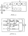
- FIG. 1 there is shown schematically a shaping station of a processing machine - a cutting machine in the example chosen - of a preprinted web, in which a web 1 of preprinted material, cut a supply coil (not shown), passes in the direction of arrow F in a device 2 with supply roller and pressure roller, then in front of a photoelectric cell 3, before reaching a rotary knife 4, mechanically connected to an encoder 5.
- the feed roller of the device 2 is driven by a motor M1, via a phase shifter 6, the phase shift input of which is controlled by a correction motor M2.
- the rotary knife 4 is driven in synchronism with the motor M1.
- the register is ensured by the register 10 essentially comprising a sensor 11, a power control 12 for the correction motor M2, a processing unit (CPU) 13, a device 14 for access and display for the operator, and a power supply 15.
- the register 10 essentially comprising a sensor 11, a power control 12 for the correction motor M2, a processing unit (CPU) 13, a device 14 for access and display for the operator, and a power supply 15.
- the signal from the photocell 3, and the signal from the encoder 5 are supplied to the sensor 11 which includes a sampling circuit 21, which receives at its input 2la the signal from the cell 3, samples it in synchronism with the encoder pulses, received at its input 21b and, by means of an analog-digital converter, supplies at its output 21c a digital value corresponding to the instantaneous amplitude of the signal of the cell.
- a sampling circuit 21 which receives at its input 2la the signal from the cell 3, samples it in synchronism with the encoder pulses, received at its input 21b and, by means of an analog-digital converter, supplies at its output 21c a digital value corresponding to the instantaneous amplitude of the signal of the cell.
- the encoder signals consist of a train of identical position pulses, extending over one revolution of the encoder, and an index pulse for each revolution of the encoder, and therefore of the knife.
- the encoder position pulse train also feeds the increment input 22a of the counter 22, which provides at its output 22c a position and addressing signal at input 23b of a memory 23 receiving at its input 23a the instantaneous digital value of the signal from cell 3 for the corresponding pulse of the encoder.
- Each digital value of the sampled signal is thus placed in memory at an address whose serial number corresponds to that of the corresponding pulse of the encoder, and therefore to the associated position of the rotary knife 4.
- the index pulse of the encoder feeds the reset input 23b of the counter, and causes the reset of the latter, the digital values received at the input 23a of the memory after a pulse of index being therefore written from the first address in memory, and replacing the values written in the previous cycle.
- the output 22c of the counter also supplies the processing unit (CPU) 13, which controls the analysis of the memory.
- CPU processing unit
- the processing unit triggers, during a writing cycle, the analysis of the memory from the first significant value beyond the gap resulting from the previous cycle, so that the the gap moves from cycle to cycle in memory.
- the analysis during the writing cycle (i - 1) stopped writing to the address Xk
- the analysis during the cycle i will be triggered immediately after writing the new value to the address Xk , and will relate to the sequence of addresses starting from x k + 1 to reach Xk , considering the memory as a closed loop.
- the first encoder cycle, terminated by the first index pulse, will generally be incomplete.
- the processing unit (CPU) 13 can either neglect this incomplete first cycle, without performing an analysis, or, if it has in memory the number N of encoder position pulses for a complete cycle, perform the first analysis when it has received from the counter 22 a number N of pulses.
- the processing unit then performs the analysis of the memory, and keeps in memory the position of the counter at the end of the analysis, position from which the following analysis will be carried out, relating to a complete cycle.
- the latter then processes the signal and sends the desired correction signal to the control circuit 24 of the correction motor, acting on the phase shifter 6 to advance or delay the advance of the preprinted web 1 relative to the rotary knife 4.
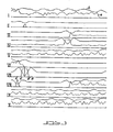
- FIG. 3 is a graph showing the evolution curve of the signal from cell 3, at input 21 a of the sampling circuit 21 (curve a), and of the function calculated in the processing unit (CPU) 13 (curve b); for ease of representation, the horizontal axis has been divided into successive portions at X, together covering a full cycle of the rotary knife.
- Figure 4 is an operating flowchart of the method of the invention operating in two modes, namely a locating mode and a regulation mode.
- locating mode is meant here an operating mode in which the content of all the memory 23, covering one revolution of the rotary knife 4, is analyzed to identify and locate the chosen locus. It is in this mode that the register is automatically placed when the machine is started, and it can also be the only operating mode, in a simplified version of the process.
- the content of the memory is analyzed to identify and locate the series of numerical values best corresponding to the reference defined by the operator.
- Block 101 validates the identified benchmark; if the benchmark is invalidated, no action is taken until the next cycle; if the benchmark is validated, the processing unit examines the speed of the machine (block 102) to determine whether it falls within a possibly prescribed speed interval (the method of the invention is essentially speed independent).
- the system simply verifies that it is instructed to operate automatically. It is indeed useful to provide for a deactivation of the register by the operator in certain cases, for example in the presence of a zone of pre-printed tape of poor quality, unusable, for which it is not useful to carry out a setting register.
- the system In block 104, the system generates the correction signal desired for the phase shifter.
- a correction In the locating mode, a correction purely proportional to the error is suitable, but it is of course possible to provide for a correction by means of a PI (proportional-integrator) or PID (proportional-integrator-derivative) regulator; these correction methods are well known, and there is no need to dwell on them here.
- PI proportional-integrator
- PID proportional-integrator-derivative
- the error is compared to a predefined error interval; if the error leaves the predefined interval, the system continues to operate in tracking mode. If it falls in the interval, the system activates the regulation mode, placing the desired setpoint in block 107.
- the reference mark has been identified and brought back into the predefined error interval in block 105.
- the system is then content to analyze the memory in the corresponding memory area, to locate the coordinate system and calculate its position (block 200).
- the localized reference mark is validated or invalidated in block 201, its invalidation causing a return to the locating mode (block 204).
- the reference being validated in block 201 the system monitors the speed of the machine in block 202 to determine whether it falls within a possibly prescribed speed interval.
- phase shifter motor Depending on the position calculated in block 200, and in the presence of an activation instruction in block 203, it then applies the desired correction signal to the phase shifter motor, via a PI regulator (proportional -integrator).
- PI regulator proportional -integrator
- the operator introduces (by his keyboard or another suitable device) at least the width (in the direction of travel of the strip) of the mark which he has chosen, and possibly his color code, and chooses an operating speed of the machine, generally the lowest possible speed of the latter ensuring its correct operation.
- this zone is not in itself critical, and is independent of the width of the marker.
- this width must be simply sufficient to provide a significant number of "zero" numerical values (that is to say corresponding in fact to the numerical values associated with the virgin material).
- This blank area on either side of the marker is used, in tracking mode, to distinguish markers of the same color, but of different width.
- the processing unit calculates the number of samples of the signal, and therefore the corresponding number of memory addresses to which the digital values must have a value determined by the color code. On either side of these values, the processing unit associates a number of "zero" values (in the sense mentioned above) corresponding to the predefined blank interval on either side of the reference.
- a reference mark in the processing unit in the form a0 bX a0, where a and b respectively represent the width of the blank area and of the signal, relative to the pulses of the encoder, 0 the associated digital value to the blank strip, and X the numerical value associated with the color code of the marker.
- the register samples the detector signal (curve a in Figure 3) in synchronism with the encoder pulses (in the simplest case, on each encoder pulse, but one can also provide a sampling every 2, 3, 4 ... pulses).
- Each sample of the analog signal is converted into a digital value, in an analog-to-digital converter, and the successive digital values obtained on a cycle of the rotary knife 4 are stored in the memory 23, at successive addresses.
- the encoder index pulse resets the counter 22 to zero, the following values then being written into memory from the start address, replacing the previous values.
- the analysis process then begins, when the processing unit has received a position signal from the counter corresponding to the end of the previous analysis.
- the analysis step can be 1, for maximum precision, but in practical cases we can be satisfied with a larger step, for example 2, 3, 4 ..., depending on the quality printing and the width of the mark, the precision of the processing unit and the nature of the blank background of the material (uniform or non-uniform background).
- the register selects the address presenting the absolute minimum of the function b.
- the serial number in the memory of the address retained at the end of exploration is a measure of the position of the center of the coordinate system with respect to the index pulse of the encoder, from which one easily draws the position of the center of the coordinate system with respect to the shaping tool, and therefore the numerical difference between this position and the zero reference position.
- the register still verifies that the benchmark it has identified is a valid benchmark, by comparing the value of the minimum obtained with a threshold value, on either side of zero. If the identified marker does not satisfy this condition, the tracking process is stopped on this cycle, and resumed at the end of the next cycle of the shaping member.
- the register then supplies the phase shifter motor with a signal proportional to the deviation, to ensure the correction, of my known.
- the error can be permanently displayed on the operator's console, so that the operator can decide at the appropriate time to increase the speed of the machine to its operating speed.
- Starting at low speed has the obvious advantage of reducing waste, since the phase shifter, given the limited power and speed of its motor, allows greater correction per cycle at low machine speed. .
- the register switches to regulation mode.
- the benchmark is already identified and located within a predefined interval, and the corrections to be made at this stage are reduced.
- the analysis of the memory 23 is limited here to an analysis of the zone corresponding to the predefined interval.
- the processing unit will here trigger the analysis when the position signal of the counter 22 will indicate to it that the sampling has extended until the end of the interval concerned, and will extend its analysis over said interval, which must be greater than the width of the mark, increased by the maximum position error allowed in regulation mode, on either side of the ideal position.
- the register In the event of rejection, the register automatically returns to tracking mode, to analyze the complete content of the memory.
- the position error is supplied to a regulator P1, which supplies the appropriate correction signal, in known manner, to the phase shifter, and the operation is repeated in the following cycle.
- an ideal detector signal is shown between A and B on line VII; this signal includes a zone of zero level, A-A 'and B-B' on either side of a peak of marked amplitude and having a constant amplitude plateau.
- Such a signal corresponds to the signal of a cell in front of which a printed mark passes, of width (in the direction of travel of the strip) greater than the width of the beam of the cell; in the case of line VII, the printed mark is separated from the printed format by a blank area on both sides, while it is embedded in a uniform print format or colored background in the case of the line IV.
- the amplitude of the signal is a function of the color of the marker, and possibly its length (direction perpendicular to the direction of travel of the strip) and its width (direction of travel of the strip), if these are less than the length and width of the photocell beam; in practice, however, it is generally arranged for the length and width of the marker to be greater than the corresponding dimensions of the cell beam, so that these parameters do not intervene.
- the method of the invention allows the identification of a mark of the desired width on a uniform background, the curve b having for this mark l 'characteristic evolution with a marked minimum, separated by two maxima, the minimum having however, in the case where the background is colored, a value deviating more strongly from the zero value, than in the case where the background is white.
- an input of the background color code can be provided on the operator console, allowing the value "0" of the sequence a0 bX a0 of set values to be adjusted to a value corresponding to that generated. by the background signal of the band, to bring the minimum value to zero.
- the method of the invention also makes it possible, by placing the mark in the form of a digital sequence, to choose a mark in the printed format itself, provided that it is sufficiently characteristic.
- such a complex reference mark can no longer be entered in the register by its width and color alone, but it can be entered for example by examination by the operator of the content of the memory 23 after a cycle of the machine, to determining the minimum width zone having the desired uniqueness characteristic, the content of this zone of the memory then being transferred into the setpoint.
- the method is of course not limited to the example of application described, relating to a rotary knife shaping machine, but applies to any process in which a strip runs in synchronism with a tool - rotary or not working on a cycle, and the position of which can be defined unequivocally with respect to an encoder or the like placed on its control shaft.
- each station being provided with its own register - possibly working on separate marks - and compensation flanges being provided for the strip between each station.
- the processing unit can calculate in tracking mode a function other than the described minimum function, for example a function having a maximum at the location of the benchmark.
- the memory analysis should not be done every cycle either, but can be done every 2, 3, 4 ... cycles. In this case, as in the case of the operating mode with regulation, with window, the analysis can always be triggered at the same address, the problem of the "gap" not arising.
Landscapes
- Engineering & Computer Science (AREA)
- Mechanical Engineering (AREA)
- Inking, Control Or Cleaning Of Printing Machines (AREA)
- Controlling Rewinding, Feeding, Winding, Or Abnormalities Of Webs (AREA)
- Labeling Devices (AREA)
- Agricultural Chemicals And Associated Chemicals (AREA)
- Vessels, Lead-In Wires, Accessory Apparatuses For Cathode-Ray Tubes (AREA)
- Paper (AREA)
Claims (8)
Priority Applications (1)
| Application Number | Priority Date | Filing Date | Title |
|---|---|---|---|
| AT88870160T ATE57160T1 (de) | 1987-10-20 | 1988-10-19 | Verfahren zur regelung oder zur aufrechterhaltung des registers einer bahn aus vorbedrucktem material mit einer anfaenglich automatischen registereinstellung. |
Applications Claiming Priority (2)
| Application Number | Priority Date | Filing Date | Title |
|---|---|---|---|
| BE8701190 | 1987-10-20 | ||
| BE8701190A BE1001012A3 (fr) | 1987-10-20 | 1987-10-20 | Procede de reperage et de regulation de la mise en registre d'une bande de materiau preimprime. |
Publications (2)
| Publication Number | Publication Date |
|---|---|
| EP0313541A1 EP0313541A1 (de) | 1989-04-26 |
| EP0313541B1 true EP0313541B1 (de) | 1990-10-03 |
Family
ID=3882931
Family Applications (1)
| Application Number | Title | Priority Date | Filing Date |
|---|---|---|---|
| EP88870160A Expired - Lifetime EP0313541B1 (de) | 1987-10-20 | 1988-10-19 | Verfahren zur Regelung oder zur Aufrechterhaltung des Registers einer Bahn aus vorbedrucktem Material mit einer anfänglich automatischen Registereinstellung |
Country Status (8)
| Country | Link |
|---|---|
| US (1) | US4994975A (de) |
| EP (1) | EP0313541B1 (de) |
| AT (1) | ATE57160T1 (de) |
| BE (1) | BE1001012A3 (de) |
| CA (1) | CA1325835C (de) |
| DE (1) | DE3860750D1 (de) |
| ES (1) | ES2018717B3 (de) |
| GR (1) | GR3001221T3 (de) |
Families Citing this family (34)
| Publication number | Priority date | Publication date | Assignee | Title |
|---|---|---|---|---|
| US5224640A (en) * | 1990-01-22 | 1993-07-06 | Sequa Corporation | Off-line web finishing system |
| US5129568A (en) * | 1990-01-22 | 1992-07-14 | Sequa Corporation | Off-line web finishing system |
| FR2659899B1 (fr) * | 1990-03-23 | 1992-07-24 | Gravurex | Procede pour effectuer automatiquement une operation sur des motifs realises dans une meme bande de materiau souple, et dispositif de mise en óoeuvre de ce procede. |
| US5170708A (en) * | 1992-01-02 | 1992-12-15 | Rdp Marathon Inc. | Register control device for a printing press |
| DE4218764A1 (de) * | 1992-06-06 | 1993-12-09 | Heidelberger Druckmasch Ag | Verfahren zur Positionierung eines Registermarkensensors an einer Bogendruckmaschine |
| US5455764A (en) * | 1993-09-09 | 1995-10-03 | Sequa Corporation | Register control system, particularly for off-line web finishing |
| DE4403861C2 (de) * | 1994-02-08 | 1998-08-20 | Heidelberger Druckmasch Ag | Verfahren zum Erzeugen eines mehrfarbigen Druckes mit einer Druckmaschine in mindestens zwei verschiedenen Durchläufen |
| AT400545B (de) * | 1994-03-18 | 1996-01-25 | Boehler Ybbstalwerke | Verfahren und stanzeinrichtung zur herstellung von schneidlinien mit ausnehmungen |
| US5967394A (en) | 1994-11-04 | 1999-10-19 | Roll Systems, Inc. | Method and apparatus for pinless feeding of web to a utilization device |
| EP1063191A1 (de) * | 1994-11-04 | 2000-12-27 | Roll Systems, Inc. | Bahnregisterregler |
| US5979732A (en) * | 1994-11-04 | 1999-11-09 | Roll Systems, Inc. | Method and apparatus for pinless feeding of web to a utilization device |
| US5659538A (en) * | 1995-03-27 | 1997-08-19 | The Procter & Gambel Company | Diaper registration control system |
| US5777879A (en) * | 1995-09-05 | 1998-07-07 | Minnesota Mining And Manufacturing Company | Process-to-mark control system |
| US6928929B1 (en) * | 1996-03-25 | 2005-08-16 | The Procter & Gamble Company | Process for making sheet having indicia registered with lines of termination |
| US5802974A (en) * | 1996-03-25 | 1998-09-08 | The Procter & Gamble Company | Apparatus for sheet having indicia registered with lines of termination |
| US5828075A (en) * | 1996-10-11 | 1998-10-27 | Hurletron, Incorporated | Apparatus for scanning colored registration marks |
| EP0882588B1 (de) * | 1997-06-02 | 2001-11-07 | Maschinenfabrik Wifag | Registerhaltige Abstimmung von Druckzylindern einer Rollenrotationsmaschine |
| EP1030782B1 (de) | 1997-11-10 | 2001-05-30 | Océ Printing Systems GmbH | Verfahren und vorrichtung zum transport eines vorbedruckten, bahnförmigen aufzeichnungsträgers in einem druckgerät |
| US6325480B1 (en) | 1998-07-28 | 2001-12-04 | Eastman Kodak Company | Ink jet printer and method capable of forming a plurality of registration marks on a receiver and sensing the marks formed thereby |
| US6591746B2 (en) | 2001-06-13 | 2003-07-15 | Hurletron, Incorporated | Registration system for printing press |
| US7661344B2 (en) * | 2003-07-29 | 2010-02-16 | Beaudry Wallace J | Method and apparatus for die cutting a web |
| US7092781B2 (en) * | 2004-12-10 | 2006-08-15 | The Procter & Gamble Company | Method of controlling tension in a web |
| US20090283002A1 (en) * | 2005-09-02 | 2009-11-19 | Stephan Schultze | Method for printing correction |
| US7967407B2 (en) * | 2006-02-03 | 2011-06-28 | R.R. Donnelley | Use of a sense mark to control a printing system |
| US20090158950A1 (en) * | 2006-04-10 | 2009-06-25 | Cc1 Inc. | Method and apparatus for re-registering a mechanical drive press |
| US7222436B1 (en) | 2006-07-28 | 2007-05-29 | The Procter & Gamble Company | Process for perforating printed or embossed substrates |
| US20080022872A1 (en) * | 2006-07-28 | 2008-01-31 | The Procter & Gamble Company | Apparatus for perforating printed or embossed substrates |
| US8753026B2 (en) * | 2007-06-29 | 2014-06-17 | R.R. Donnelley & Sons Company | Use of a sense mark to control a printing system |
| DE102009012436A1 (de) | 2009-03-11 | 2010-09-23 | OCé PRINTING SYSTEMS GMBH | Verfahren und Vorrichtung zum Überprüfen der auf ein Trägermaterial gedruckten Farbauszüge |
| US9098903B2 (en) * | 2009-07-21 | 2015-08-04 | R.R. Donnelley & Sons Company | Systems and methods for detecting alignment errors |
| AT515932B1 (de) | 2014-10-27 | 2016-01-15 | Bernecker & Rainer Ind Elektronik Gmbh | Verfahren und Vorrichtung zur Detektion einer Druckmarke |
| US10370214B2 (en) | 2017-05-31 | 2019-08-06 | Cryovac, Llc | Position control system and method |
| JP7139211B2 (ja) * | 2018-10-12 | 2022-09-20 | 住友重機械工業株式会社 | 情報処理装置、印刷システム及び情報処理方法 |
| CN111731907B (zh) * | 2019-03-25 | 2022-03-08 | 西门子工厂自动化工程有限公司 | 自动调整横切机切刀角度的方法和横切机 |
Family Cites Families (14)
| Publication number | Priority date | Publication date | Assignee | Title |
|---|---|---|---|---|
| US2050316A (en) * | 1934-03-16 | 1936-08-11 | Westinghouse Electric & Mfg Co | Cutter register control |
| US3264983A (en) * | 1964-02-18 | 1966-08-09 | Champlain Company Inc | Registration system for a moving web |
| US3594552A (en) * | 1968-04-17 | 1971-07-20 | Hurletron Inc | System and method for indication and control of circumferential register |
| US3601587A (en) * | 1969-10-06 | 1971-08-24 | Hurletron Inc | Register control system and method |
| US3914582A (en) * | 1974-05-28 | 1975-10-21 | Hurletronaltair Inc | Display system and method for registration control equipment |
| DE2643481A1 (de) * | 1976-09-27 | 1978-03-30 | Siemens Ag | Einrichtung zum automatischen erkennen einer registerpassmarke |
| US4243925A (en) * | 1978-09-27 | 1981-01-06 | Web Printing Controls Co., Inc. | Register control system for web operating apparatus |
| US4318176A (en) * | 1980-03-03 | 1982-03-02 | Hurletronaltair, Inc. | Computerized press controls |
| US4366753A (en) * | 1980-04-11 | 1983-01-04 | Baldwin Korthe Web Controls, Inc. | Circumferential registration control system |
| US4384500A (en) * | 1980-11-20 | 1983-05-24 | Owens-Illinois, Inc. | Registration control for a label cutoff apparatus |
| DE3302798C2 (de) * | 1983-01-28 | 1987-03-05 | M.A.N.- Roland Druckmaschinen AG, 6050 Offenbach | Vorrichtung zum Voreinstellen an Druckmaschinen |
| US4719575A (en) * | 1984-09-14 | 1988-01-12 | Web Printing Control Co., Inc. | Method and apparatus for controlling web handling machinery |
| US4648540A (en) * | 1984-11-27 | 1987-03-10 | Moore Business Forms Inc | Size independent modular web processing line and modules |
| US4839814A (en) * | 1985-01-29 | 1989-06-13 | Moore Business Forms, Inc. | Size independent modular web processing line and modules |
-
1987
- 1987-10-20 BE BE8701190A patent/BE1001012A3/fr not_active IP Right Cessation
-
1988
- 1988-10-19 DE DE8888870160T patent/DE3860750D1/de not_active Expired - Lifetime
- 1988-10-19 AT AT88870160T patent/ATE57160T1/de not_active IP Right Cessation
- 1988-10-19 EP EP88870160A patent/EP0313541B1/de not_active Expired - Lifetime
- 1988-10-19 ES ES88870160T patent/ES2018717B3/es not_active Expired - Lifetime
- 1988-10-20 CA CA000580824A patent/CA1325835C/en not_active Expired - Fee Related
- 1988-10-20 US US07/260,268 patent/US4994975A/en not_active Expired - Fee Related
-
1990
- 1990-12-20 GR GR90401104T patent/GR3001221T3/el unknown
Also Published As
| Publication number | Publication date |
|---|---|
| ES2018717B3 (es) | 1991-05-01 |
| BE1001012A3 (fr) | 1989-06-13 |
| GR3001221T3 (en) | 1992-07-30 |
| DE3860750D1 (de) | 1990-11-08 |
| US4994975A (en) | 1991-02-19 |
| ATE57160T1 (de) | 1990-10-15 |
| CA1325835C (en) | 1994-01-04 |
| EP0313541A1 (de) | 1989-04-26 |
Similar Documents
| Publication | Publication Date | Title |
|---|---|---|
| EP0313541B1 (de) | Verfahren zur Regelung oder zur Aufrechterhaltung des Registers einer Bahn aus vorbedrucktem Material mit einer anfänglich automatischen Registereinstellung | |
| EP1132203B1 (de) | Verfahren und Vorrichtung zum automatischen Voreinstellen des Registers von Rotationsdruckmaschinen | |
| EP0452769B1 (de) | Überwachung der Druckqualität und der Schneidqualität in einer Produktionsanlage zur Herstellung von Verpackungen | |
| CN100523794C (zh) | 用于确定卷烟制品或过滤棒的一或多个物理性质的方法和设备 | |
| JP2017538599A5 (de) | ||
| BE1006796A5 (fr) | Appareil et procede pour maintenir la synchronisation des perforations. | |
| JPH0655495A (ja) | ウォータマーク検知 | |
| FR2490554A1 (fr) | Procede et dispositif pour controler et commander l'impression en couleurs d'une imprimeuse polychrome | |
| FR2638675A1 (fr) | Machine a fabriquer des sacs en matiere plastique et systeme de commande du fonctionnement d'une telle machine | |
| EP1769916B1 (de) | Vorrichtung und Verfahren zum Kennzeichnen von zylindrischen Objekten | |
| JP2005505410A (ja) | にかわ像を監視する方法と装置 | |
| FR2529510A1 (fr) | Imprimante avec un dispositif automatique d'empilage | |
| US4383537A (en) | Method and apparatus for inspecting and cutting cigar wrappers | |
| US20030089208A1 (en) | Apparatus for measuring the wear of a doctor blade and method in measuring the wear of a doctor blade and in controlling a paper machine | |
| US4147078A (en) | Treatment of web material | |
| EP1171371B1 (de) | Anlage für die behandlung von werkstücken wie etiketten oder bekleidungshülsen von flaschen | |
| EP0274294A1 (de) | Fahrkartenausgabevorrichtung | |
| EP0192855A2 (de) | Vorrichtung zum Markieren eines Reifens | |
| EP0557198B1 (de) | Vorrichtung und Verfahren zum Bestimmen der Kontaktposition zwischen zwei Teilen von denen mindestens eine mobil ist | |
| GB2186226A (en) | Rotary cutting machines | |
| EP0639420A1 (de) | Verfahren und Vorrichtung zum elektroerosiven Aushöhlen von 3-D-Kontouren mit einer dünnen rotierenden Elektrode | |
| CA2193509C (fr) | Dispositif et procede de pilotage d'une machine d'impression, notamment de tambour d'affranchisseur | |
| JP3273803B2 (ja) | シガレット製造機における巻たばこの印刷濃度調整装置 | |
| CH679141A5 (de) | ||
| US11052682B2 (en) | Identifying printing substrate types |
Legal Events
| Date | Code | Title | Description |
|---|---|---|---|
| PUAI | Public reference made under article 153(3) epc to a published international application that has entered the european phase |
Free format text: ORIGINAL CODE: 0009012 |
|
| AK | Designated contracting states |
Kind code of ref document: A1 Designated state(s): AT BE CH DE ES FR GB GR IT LI LU NL SE |
|
| 17P | Request for examination filed |
Effective date: 19890516 |
|
| 17Q | First examination report despatched |
Effective date: 19890911 |
|
| GRAA | (expected) grant |
Free format text: ORIGINAL CODE: 0009210 |
|
| AK | Designated contracting states |
Kind code of ref document: B1 Designated state(s): AT BE CH DE ES FR GB GR IT LI LU NL SE |
|
| REF | Corresponds to: |
Ref document number: 57160 Country of ref document: AT Date of ref document: 19901015 Kind code of ref document: T |
|
| REF | Corresponds to: |
Ref document number: 3860750 Country of ref document: DE Date of ref document: 19901108 |
|
| ITF | It: translation for a ep patent filed | ||
| GBT | Gb: translation of ep patent filed (gb section 77(6)(a)/1977) | ||
| PLBE | No opposition filed within time limit |
Free format text: ORIGINAL CODE: 0009261 |
|
| STAA | Information on the status of an ep patent application or granted ep patent |
Free format text: STATUS: NO OPPOSITION FILED WITHIN TIME LIMIT |
|
| 26N | No opposition filed | ||
| REG | Reference to a national code |
Ref country code: GR Ref legal event code: FG4A Free format text: 3001221 |
|
| ITTA | It: last paid annual fee | ||
| EPTA | Lu: last paid annual fee | ||
| EAL | Se: european patent in force in sweden |
Ref document number: 88870160.4 |
|
| PGFP | Annual fee paid to national office [announced via postgrant information from national office to epo] |
Ref country code: FR Payment date: 19951024 Year of fee payment: 8 |
|
| PGFP | Annual fee paid to national office [announced via postgrant information from national office to epo] |
Ref country code: GB Payment date: 19951025 Year of fee payment: 8 |
|
| PGFP | Annual fee paid to national office [announced via postgrant information from national office to epo] |
Ref country code: CH Payment date: 19951027 Year of fee payment: 8 |
|
| PGFP | Annual fee paid to national office [announced via postgrant information from national office to epo] |
Ref country code: SE Payment date: 19951030 Year of fee payment: 8 Ref country code: GR Payment date: 19951030 Year of fee payment: 8 Ref country code: ES Payment date: 19951030 Year of fee payment: 8 |
|
| PGFP | Annual fee paid to national office [announced via postgrant information from national office to epo] |
Ref country code: NL Payment date: 19951031 Year of fee payment: 8 Ref country code: DE Payment date: 19951031 Year of fee payment: 8 Ref country code: BE Payment date: 19951031 Year of fee payment: 8 Ref country code: AT Payment date: 19951031 Year of fee payment: 8 |
|
| PGFP | Annual fee paid to national office [announced via postgrant information from national office to epo] |
Ref country code: LU Payment date: 19951101 Year of fee payment: 8 |
|
| PG25 | Lapsed in a contracting state [announced via postgrant information from national office to epo] |
Ref country code: LU Free format text: LAPSE BECAUSE OF NON-PAYMENT OF DUE FEES Effective date: 19961019 Ref country code: GB Effective date: 19961019 Ref country code: AT Effective date: 19961019 |
|
| PG25 | Lapsed in a contracting state [announced via postgrant information from national office to epo] |
Ref country code: SE Effective date: 19961020 |
|
| PG25 | Lapsed in a contracting state [announced via postgrant information from national office to epo] |
Ref country code: ES Free format text: LAPSE BECAUSE OF THE APPLICANT RENOUNCES Effective date: 19961021 |
|
| PG25 | Lapsed in a contracting state [announced via postgrant information from national office to epo] |
Ref country code: LI Effective date: 19961031 Ref country code: CH Effective date: 19961031 Ref country code: BE Effective date: 19961031 |
|
| BERE | Be: lapsed |
Owner name: MINSCHART MARC GUSTAVE Effective date: 19961031 |
|
| PG25 | Lapsed in a contracting state [announced via postgrant information from national office to epo] |
Ref country code: GR Free format text: THE PATENT HAS BEEN ANNULLED BY A DECISION OF A NATIONAL AUTHORITY Effective date: 19970430 |
|
| PG25 | Lapsed in a contracting state [announced via postgrant information from national office to epo] |
Ref country code: NL Effective date: 19970501 |
|
| REG | Reference to a national code |
Ref country code: GR Ref legal event code: MM2A Free format text: 3001221 |
|
| GBPC | Gb: european patent ceased through non-payment of renewal fee |
Effective date: 19961019 |
|
| REG | Reference to a national code |
Ref country code: CH Ref legal event code: PL |
|
| PG25 | Lapsed in a contracting state [announced via postgrant information from national office to epo] |
Ref country code: FR Effective date: 19970630 |
|
| NLV4 | Nl: lapsed or anulled due to non-payment of the annual fee |
Effective date: 19970501 |
|
| PG25 | Lapsed in a contracting state [announced via postgrant information from national office to epo] |
Ref country code: DE Effective date: 19970701 |
|
| EUG | Se: european patent has lapsed |
Ref document number: 88870160.4 |
|
| REG | Reference to a national code |
Ref country code: FR Ref legal event code: ST |
|
| REG | Reference to a national code |
Ref country code: ES Ref legal event code: FD2A Effective date: 19991007 |
|
| PG25 | Lapsed in a contracting state [announced via postgrant information from national office to epo] |
Ref country code: IT Free format text: LAPSE BECAUSE OF NON-PAYMENT OF DUE FEES;WARNING: LAPSES OF ITALIAN PATENTS WITH EFFECTIVE DATE BEFORE 2007 MAY HAVE OCCURRED AT ANY TIME BEFORE 2007. THE CORRECT EFFECTIVE DATE MAY BE DIFFERENT FROM THE ONE RECORDED. Effective date: 20051019 |