EP0312822A2 - Drucker und zugehöriger Mehrfunktionsständer - Google Patents
Drucker und zugehöriger Mehrfunktionsständer Download PDFInfo
- Publication number
- EP0312822A2 EP0312822A2 EP88116281A EP88116281A EP0312822A2 EP 0312822 A2 EP0312822 A2 EP 0312822A2 EP 88116281 A EP88116281 A EP 88116281A EP 88116281 A EP88116281 A EP 88116281A EP 0312822 A2 EP0312822 A2 EP 0312822A2
- Authority
- EP
- European Patent Office
- Prior art keywords
- printer
- stand
- rod
- desk
- base
- Prior art date
- Legal status (The legal status is an assumption and is not a legal conclusion. Google has not performed a legal analysis and makes no representation as to the accuracy of the status listed.)
- Granted
Links
Images


Classifications
-
- B—PERFORMING OPERATIONS; TRANSPORTING
- B41—PRINTING; LINING MACHINES; TYPEWRITERS; STAMPS
- B41J—TYPEWRITERS; SELECTIVE PRINTING MECHANISMS, i.e. MECHANISMS PRINTING OTHERWISE THAN FROM A FORME; CORRECTION OF TYPOGRAPHICAL ERRORS
- B41J11/00—Devices or arrangements of selective printing mechanisms, e.g. ink-jet printers or thermal printers, for supporting or handling copy material in sheet or web form
- B41J11/58—Supply holders for sheets or fan-folded webs, e.g. shelves, tables, scrolls, pile holders
-
- B—PERFORMING OPERATIONS; TRANSPORTING
- B41—PRINTING; LINING MACHINES; TYPEWRITERS; STAMPS
- B41J—TYPEWRITERS; SELECTIVE PRINTING MECHANISMS, i.e. MECHANISMS PRINTING OTHERWISE THAN FROM A FORME; CORRECTION OF TYPOGRAPHICAL ERRORS
- B41J29/00—Details of, or accessories for, typewriters or selective printing mechanisms not otherwise provided for
- B41J29/06—Special supports, platforms or trolleys for supporting machines on tables
Definitions
- the present invention relates to a printer and related multi functional stand, particularly a printer for data processing systems, personal computers and like.
- Such printers are generally intended for printing on a continuous form fanfolded so as to constitute a paper stack.
- printers with an "ad hoc" pedestal having a first basket for storing the continuous form to be printed and a second basket for collecting the printed form.
- the two baskets are loacated in a way suitable for assuring a correct paper feeding to the printer and the collection of the printed form.
- the multifunctional stand allows for an easy and versatile installation in an office environment, meeting various possible needs.
- the stand In a first working position the stand prevents interference of the continuous form with a possible edge of the laying down plane.
- the stand In a second working position the stand prevents the simultaneous feeding of a plurality of modules of a continuous form.
- the stand In a third working position the stand holds the printer some how lifted on a laying down plane and allows for the insertion, at least partially below the printer, of a continuous form stack to be printed.
- the stand can be easily mounted in the printer in a concealed way, so that the stand is not visible and does not disturbs the printer appearance when the installation operative conditions do not require its use.
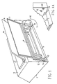
- FIG. 1 it shows in perspective view the body 1 of a printer, the body consisting in a base and a cover fixed each other and forming a casing where the printer mechanisms and circuits are contained.
- the printer rear has an opening, closed by a panel 2. Through such an opening it is possible to enter an internal space where continuous form feeding tractors 3,4 are located.
- Panel 2 is hinged to the printer body on the upper edge of the opening and, when closed, leaves a slot at the lower edge of the opening, allowing for the introduction of the printing form within the body.
- the rear, lower edge of the body is suitably shaped so as to provide a guiding surface 5 to the continuous form entering the printer.
- the upper panel 9 of the cover has a transparent window screen allowing to view inside, in the printing zone, and a slot 7 for the output of the printed form from the body.
- a reading desk 8 is also provided, which extends up from the upper panel 9 with a suitable slope and onto which the printed form lays down.
- the upper edge of the reading desk is suitably rounded and the printing form, once reached the upper edge tends to fall on the rear of the printer.
- the printer is provided with a multifunctional stand which can assume several operating positions.
- the stand consists of a relatively rigid element, shaped in form of a square C or a handle and preferably implemented from a metal rod having round section.
- the stand comprises a rectilinear rod 11 having a length substantially equal to or slighty less than the width of the printer rear opening.
- Rod 11 terminates in two arms 12,13 substantially at right angle with rod 11, and having a length substantially equal to or sligthy less than the height of the rear opening.
- Each of the arms 12,13 terminates in an appendix 14,15, folded at right angle and parallel to rod 11, and outward oriented, relative to the space comprised between the two arms.
- the side edges of the rear opening each have an opening located close to the lower edge.
- the two appendixes are inserted in such openings, so that the stand is hinged in such seats and can pivot around an axis defined by such seats.
- the lower-rear edge of the printer body has two throats 17,18 which enable arms 12,13 to be inserted in such throats, so that the stand can pivot for a rotational arc greater than 180 deg. around its rotation axis, as shown by the arrow 16.
- the stand can therefore take any position comprised between two extreme positions, one in which the stand is housed in the rear space of the printer, as shown in figure 1, and one in which the stand is placed below the printer base, with a suitable forward orientation.
- Figure 1A shows, for a better understanding, a portion of the rear portion of the printer where a seat 19 is clearly visible, for housing the appendix 15 of the stand.
- Throat 18 is further shown where a portion of arm 13 is inserted when the stand is placed downward.
- a portion of the lower guiding edge 5 for the continuous form can also be seen.
- the side wall of the rear opening has a prominence 20, suitable shaped, which constitutes a stop for the pivoting of the stand and defines for it a stable position in which the stand extends rearword the printer body.
- the relative resiliency of the stand enable it to overcome the stop 20, with reasonable effort, in order to move the stand in one or the other of the two angular fields defined by stop 20.
- Figure 2 shows in sketch side view a printer laid down on a desk in the unique position permitted to the prior art printers and deprived of the invention stand.
- the printer 1 has to rest on the working plane in a position such that its rear wall is substantially in alignment with the rear edge of the working plane.
- a stack of continuous form segments 22 is placed below the table.
- the continuous form is fed through the printer by tractors 25 internal to the printer. They convey the form to a printing platen 23.
- the printed form leaves the printer, lays down on reading desk 8, goes beyond its upper edge and falls rearward of the working plane 21 fanfolding to form a collection stack 26, normally resting on the floor.
- stack 22 in order to assure an appropriate form feeding, stack 22 must be located so that the continuous form does not interfere with the rear edge of the working plane, in order to avoid undesired tearing, excessive friction and printer clogging.
- stack 22 only partially below the working plane and the need to have available, on the rear of the table, a space sufficing to locate both stack 26 and (at least partially) stack 22.
- Figure 3 shows how the use of the stand of the invention enables to overcome this limitation.
- the printer is still resting on the working plane 21 with its rear wall aligned with the rear edge 24 of the working plane.
- the stand in this case is withdrawn from the rear housing and is laid down so as to stop against the rear edge 24 of the working plane.
- the stand rod 11 works as a guiding element for the continuous form and prevents its interference with the edge 24.
- the stack 22 may therefore be located well below the working plane leaving space for partially or fully locating the collecting stack 26 below the table too.
- Figure 4 shows an alternative use of the invention stand.
- the printer is located in the front portion of the working plane and leaves available a rear portion where stack 22 may be placed.
- the stand withdrawn from the rear housing of the printer and laid down on the table, forms by its rod 11 a guide against which stack 22 is positioned.
- Rod 11 assures that the stack remains far from the printer and prevents that, owing to friction among modules of the form, the stack, particularly in the depletion phase, is sucked within the printer, with consequential clogging.
- the collecting stack may be obviously located below the table.
- Figure 5 shows an alternative installation way in which both the feeding stack 22 and the collecting stack 26 are located on a working plane.
- stand 27 is withdrawn from the printer and pulled down forward so as to act as a rear support for the printer.
- the printer is located in a forward portion of the working plane and with its front edge supported thereon, whilst the rear portion is lifted from the plane by the stand.
- the space available between the working plane and the printer bottom may be used to locate therein, at least in part, the feeding stack 22.
- stand 27 allows for a great installation versatility of the printer.
- Figure 6 shows in side sketch view a printer in which the stand 27, rather than being mounted in a rear housing is mounted on the bottom of the printer and hinged near about two rear feets. It can pivot according to the arc shown by arrow 30 and can take one or more stable positions.
- Figure 7 shows the printer of Fig. 6 with the stand steadily positioned so as to keep the rear portion of the printer lifted from the working plane.
- the stand may be housed in a suitable recess provided in the bottom of the printer, so that the presence of standing feets, providing some clearance between the bottom and the working plane, is unessential from this point of view.
Landscapes
- Handling Of Sheets (AREA)
- Pile Receivers (AREA)
- Accessory Devices And Overall Control Thereof (AREA)
Applications Claiming Priority (2)
| Application Number | Priority Date | Filing Date | Title |
|---|---|---|---|
| IT2231987 | 1987-10-19 | ||
| IT22319/87A IT1222937B (it) | 1987-10-19 | 1987-10-19 | Stampante e relativo supporto multifunzionale |
Publications (3)
| Publication Number | Publication Date |
|---|---|
| EP0312822A2 true EP0312822A2 (de) | 1989-04-26 |
| EP0312822A3 EP0312822A3 (en) | 1990-06-27 |
| EP0312822B1 EP0312822B1 (de) | 1993-03-10 |
Family
ID=11194613
Family Applications (1)
| Application Number | Title | Priority Date | Filing Date |
|---|---|---|---|
| EP88116281A Expired - Lifetime EP0312822B1 (de) | 1987-10-19 | 1988-10-01 | Drucker und zugehöriger Mehrfunktionsständer |
Country Status (4)
| Country | Link |
|---|---|
| US (1) | US4915518A (de) |
| EP (1) | EP0312822B1 (de) |
| DE (1) | DE3879081D1 (de) |
| IT (1) | IT1222937B (de) |
Family Cites Families (13)
| Publication number | Priority date | Publication date | Assignee | Title |
|---|---|---|---|---|
| US1331442A (en) * | 1920-02-17 | Typewriting-machine | ||
| GB782621A (en) * | 1955-12-15 | 1957-09-11 | Lamson Paragon Ltd | Improvements in and relating to apparatus for supporting stationery guide means for use with a typewriter |
| US3884342A (en) * | 1970-10-22 | 1975-05-20 | Monarch Marking Systems Inc | Portable data set |
| DE2316077B2 (de) * | 1973-03-30 | 1977-09-15 | Siemens AG, 1000 Berlin und 8000 München | Konzepthalter fuer schreibmaschinen oder aehnliche bueromaschinen |
| DE3014423C2 (de) * | 1980-04-15 | 1983-10-13 | Siemens Ag, 1000 Berlin Und 8000 Muenchen | Vorrichtung zur Einstellung der Neigung einer Tastatur |
| US4344612A (en) * | 1980-05-12 | 1982-08-17 | Burroughs Corporation | Sheet feeder support assembly |
| DE3208111C2 (de) * | 1982-03-06 | 1984-05-30 | Kienzle Apparate Gmbh, 7730 Villingen-Schwenningen | Druckeinrichtung in modularer Bauweise |
| JPS59229371A (ja) * | 1983-04-12 | 1984-12-22 | Seiko Epson Corp | プリンタの給紙装置 |
| JPS60271A (ja) * | 1983-06-15 | 1985-01-05 | 松下電器産業株式会社 | 冷蔵庫 |
| GB2159499B (en) * | 1984-05-21 | 1988-08-03 | Charles Robert Igna Cunningham | Stationery stand |
| DE3436684C2 (de) * | 1984-10-05 | 1986-10-02 | Siemens AG, 1000 Berlin und 8000 München | Papierführungselement für Druckeinrichtungen mit Endlospapier |
| US4725157A (en) * | 1985-07-29 | 1988-02-16 | Brother Kogyo Kabushiki Kaisha | Printing device with a pair of housings combined for relative rocking motion |
| US4808021A (en) * | 1988-03-30 | 1989-02-28 | Hewlett-Packard Company | Method and apparatus for storing accessories inside a printing device |
-
1987
- 1987-10-19 IT IT22319/87A patent/IT1222937B/it active
-
1988
- 1988-09-28 US US07/250,456 patent/US4915518A/en not_active Expired - Fee Related
- 1988-10-01 EP EP88116281A patent/EP0312822B1/de not_active Expired - Lifetime
- 1988-10-01 DE DE8888116281T patent/DE3879081D1/de not_active Expired - Lifetime
Also Published As
| Publication number | Publication date |
|---|---|
| EP0312822A3 (en) | 1990-06-27 |
| IT8722319A0 (it) | 1987-10-19 |
| EP0312822B1 (de) | 1993-03-10 |
| US4915518A (en) | 1990-04-10 |
| IT1222937B (it) | 1990-09-12 |
| DE3879081D1 (de) | 1993-04-15 |
Similar Documents
| Publication | Publication Date | Title |
|---|---|---|
| JP7089669B2 (ja) | 媒体搬送装置および画像読取装置 | |
| US4546947A (en) | Keyboard dust cover having integral copyholder | |
| US7165687B1 (en) | Storage organizer | |
| US4568212A (en) | Printer stand | |
| US4544065A (en) | Printer stand | |
| US5729430A (en) | Corner placement monitor stand | |
| CA2385459C (en) | Terminal for processing forms | |
| JP3408819B2 (ja) | 配電箱のための作業プレート | |
| US5080320A (en) | Adjustable computer printer stand | |
| EP0312822B1 (de) | Drucker und zugehöriger Mehrfunktionsständer | |
| US4610416A (en) | Book holder | |
| JPH11254788A (ja) | 画像記録装置 | |
| JPS58144045A (ja) | 排紙トレイ | |
| US6196539B1 (en) | Conveniently operated sheet-handling device | |
| KR20100011278U (ko) | 책상설치용 독서대 및 그 독서대가 설치된 책상 | |
| JP2003341858A (ja) | 大容量給紙装置 | |
| US4966289A (en) | Series of peripheral apparatuses for rail type of drafting table | |
| JP5660708B2 (ja) | 用紙収納装置及びこれを備えた天板付家具 | |
| CN221476544U (zh) | 一种可滑移带白板固定功能的笔盒及白板 | |
| KR930004098Y1 (ko) | 복사기 수동테이블의 용지지지장치 | |
| JPS6331645Y2 (de) | ||
| JPH0114439Y2 (de) | ||
| JPH0333718Y2 (de) | ||
| JPH0225634Y2 (de) | ||
| JPH0133338Y2 (de) |
Legal Events
| Date | Code | Title | Description |
|---|---|---|---|
| PUAI | Public reference made under article 153(3) epc to a published international application that has entered the european phase |
Free format text: ORIGINAL CODE: 0009012 |
|
| AK | Designated contracting states |
Kind code of ref document: A2 Designated state(s): CH DE FR GB LI NL |
|
| RAP1 | Party data changed (applicant data changed or rights of an application transferred) |
Owner name: BULL HN INFORMATION SYSTEMS ITALIA S.P.A. |
|
| PUAL | Search report despatched |
Free format text: ORIGINAL CODE: 0009013 |
|
| AK | Designated contracting states |
Kind code of ref document: A3 Designated state(s): CH DE FR GB LI NL |
|
| 17P | Request for examination filed |
Effective date: 19901019 |
|
| 17Q | First examination report despatched |
Effective date: 19920529 |
|
| GRAA | (expected) grant |
Free format text: ORIGINAL CODE: 0009210 |
|
| AK | Designated contracting states |
Kind code of ref document: B1 Designated state(s): CH DE FR GB LI NL |
|
| PG25 | Lapsed in a contracting state [announced via postgrant information from national office to epo] |
Ref country code: NL Effective date: 19930310 Ref country code: LI Effective date: 19930310 Ref country code: DE Effective date: 19930310 Ref country code: CH Effective date: 19930310 |
|
| REF | Corresponds to: |
Ref document number: 3879081 Country of ref document: DE Date of ref document: 19930415 |
|
| ET | Fr: translation filed | ||
| REG | Reference to a national code |
Ref country code: CH Ref legal event code: PL |
|
| NLV1 | Nl: lapsed or annulled due to failure to fulfill the requirements of art. 29p and 29m of the patents act | ||
| PG25 | Lapsed in a contracting state [announced via postgrant information from national office to epo] |
Ref country code: GB Effective date: 19931001 |
|
| PGFP | Annual fee paid to national office [announced via postgrant information from national office to epo] |
Ref country code: FR Payment date: 19931026 Year of fee payment: 6 |
|
| PLBE | No opposition filed within time limit |
Free format text: ORIGINAL CODE: 0009261 |
|
| STAA | Information on the status of an ep patent application or granted ep patent |
Free format text: STATUS: NO OPPOSITION FILED WITHIN TIME LIMIT |
|
| 26N | No opposition filed | ||
| GBPC | Gb: european patent ceased through non-payment of renewal fee |
Effective date: 19931001 |
|
| PG25 | Lapsed in a contracting state [announced via postgrant information from national office to epo] |
Ref country code: FR Effective date: 19950630 |
|
| REG | Reference to a national code |
Ref country code: FR Ref legal event code: ST |