EP0312045B1 - Zentrifugalextraktor - Google Patents
Zentrifugalextraktor Download PDFInfo
- Publication number
- EP0312045B1 EP0312045B1 EP19880117014 EP88117014A EP0312045B1 EP 0312045 B1 EP0312045 B1 EP 0312045B1 EP 19880117014 EP19880117014 EP 19880117014 EP 88117014 A EP88117014 A EP 88117014A EP 0312045 B1 EP0312045 B1 EP 0312045B1
- Authority
- EP
- European Patent Office
- Prior art keywords
- rotor
- centrifugal extractor
- partition
- central opening
- cylindrical member
- Prior art date
- Legal status (The legal status is an assumption and is not a legal conclusion. Google has not performed a legal analysis and makes no representation as to the accuracy of the status listed.)
- Expired
Links
Images


Classifications
-
- B—PERFORMING OPERATIONS; TRANSPORTING
- B04—CENTRIFUGAL APPARATUS OR MACHINES FOR CARRYING-OUT PHYSICAL OR CHEMICAL PROCESSES
- B04B—CENTRIFUGES
- B04B1/00—Centrifuges with rotary bowls provided with solid jackets for separating predominantly liquid mixtures with or without solid particles
- B04B1/02—Centrifuges with rotary bowls provided with solid jackets for separating predominantly liquid mixtures with or without solid particles without inserted separating walls
-
- B—PERFORMING OPERATIONS; TRANSPORTING
- B01—PHYSICAL OR CHEMICAL PROCESSES OR APPARATUS IN GENERAL
- B01D—SEPARATION
- B01D11/00—Solvent extraction
- B01D11/04—Solvent extraction of solutions which are liquid
- B01D11/0446—Juxtaposition of mixers-settlers
- B01D11/0457—Juxtaposition of mixers-settlers comprising rotating mechanisms, e.g. mixers, mixing pumps
-
- B—PERFORMING OPERATIONS; TRANSPORTING
- B01—PHYSICAL OR CHEMICAL PROCESSES OR APPARATUS IN GENERAL
- B01D—SEPARATION
- B01D11/00—Solvent extraction
- B01D11/04—Solvent extraction of solutions which are liquid
- B01D11/0476—Moving receptacles, e.g. rotating receptacles
- B01D11/048—Mixing by counter-current streams provoked by centrifugal force, in rotating coils or in other rotating spaces
Definitions
- the present invention relates to a centrifugal extractor suitable for use in nuclear fuel reprocessing.
- the centrifugal extractor for the reprocessing of a nuclear fuel is used to mix an organic solvent with a nitric acid solution in which a used nuclear fuel is dissolved for thereby preparing a mixture and, then, to centrifugally separate and extract therefrom a light liquid part which has a smaller specific gravity and contains uranium and plutonium and a heavy liquid part which has a larger specific gravity and contains fission product.
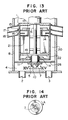
- the prior art centrifugal extractor has a housing 8 having a liquid reservoir 4 at the bottom thereof.
- a rotor 1 is suspended in the housing 8 and has a shaft 6 extending axially through the rotor.
- An impeller 7 is secured to the bottom end of the shaft 6 and surrounded by a pump casing 10 to form a centrifugal pump 5.
- the pump casing 10 is secured to the inner peripheral edge of a central opening in a lower partition 26 which forms a top wall of the liquid reservoir 4.
- the upper end of the pump casing 10 extends into the interior of the rotor 1 through a central opening 11a in a bottom end wall 11 with an annular gap 19 left between the outer peripheral surface of the pump casing 10 and the inner peripheral edge of the rotor bottom end wall 11.
- the liquid resevoir 4 is provided with liquid supply ports 2 and 3 through which the nitric acid solution and the organic solvent are fed into the reservoir 4.
- the impeller 7 of the centrifugal pump 5 When the shaft 6 is rotated, the impeller 7 of the centrifugal pump 5 is rotated to agitate and mix the two kinds of the liquids and sucks the liquids up into the interior of the rotor 1 so that the rotor is filled with a mixture of the liquids.
- the mixture in the rotor 1 is subjected to a centrifugal force and centrifugally separated into light and heavy liquid parts.
- the light liquid part is caused to flow over a light liquid gate 13 and through a series of extraction ports 15 into a light liquid outlet 17, while the heavy liquid part flows over a heavy liquid gate 14 and through another series of extraction ports 16 into a heavy liquid outlet 18.
- Radial partitions 21 are provided in the rotor 1 and secured to the shaft 6 to prevent the occurrence of slippage between the rotor and the mixture therein when the rotor is rotated.
- the annular gap 19 between the pump casing 10 and the bottom end wall 11 of the rotor 1 permits the mixture being pumped by the centrifugal pump 5 to leak out of the rotor 1 into an annular space 20 defined between the rotor 1 and the housing 8. Because the rotor 1 is rotated at a speed as high as from 3000 to 4000 r.p.m., the liquid which has leaked out of the rotor 1 into the annular space 20 is altered to mist as the liquid contacts the outer peripheral surface of the rotating rotor 1.
- the mist flows upwardly through gaps between the outer peripheral surface of the rotor 1 and the inner peripheral edges of the light and heavy liquid outlets 17 and 18 into the liquid parts being discharged from the rotor 1 through the extraction ports 15 and 16 into the liquid outlets 17 and 18, with the result that the mist not only lowers the concentrations of the liquid parts extracted from the rotor 1 but also increases the radiation deterioration of the organic solvent collected as the light liquid part.
- the centrifugal extractor comprises an outer housing provided at its bottom end with a liquid reservoir for receiving kinds of liquids to be treated, a hollow rotor rotatably mounted in the housing, pump means having an impeller disposed at the bottom end of the rotor and rotatable therewith to feed the liquids from the reservoir into the rotor, the liquids in the rotor being subjected to a centrifugal force and centrifugally separated into a plurality of liquid parts, and means for separately discharging the thus separated liquid parts out of the rotor.
- the impeller of the pump means is surrounded by a cylindrical hollow member which is connected to an inner peripheral edge of a central opening in the bottom end wall of the rotor in liquid-tight manner and communicates the interior of the rotor with the liquid reservoir.
- the cylindrical hollow member which surrounds the pump impeller is connected sealingly to the inner peripheral edge of the central opening in the bottom end wall of the rotor, the cylindrical member is operative to advantageously prevent the occurrence of leakage of the liquids from the interior of the rotor into a space between the rotor and the outer housing.
- a partition is provided in a lower part of the rotor to separate the reservoir from that part of the interior of the housing which accommodates the rotor.
- the cylindrical hollow member extends downwardly from the rotor through a central opening in the patition into the liquid reservoir with a gap of a predetermined dimension left between the outer peripheral surface of the cylindrical member and the inner peripheral edge of the central opening in the partition.
- the space between the rotor and the outer housing is communicated through the gap with the reservoir, so that gases in the space are sucked downwardly into the reservoir by the pumping means.
- the first embodiment of the centrifugal extractor of the present invention includes a cylindrical hollow rotor 1 having a shaft 6 extending axially therethrough and secured to the rotor for rotation therewith.
- Radial partition plates 21 are disposed in the rotor 1 and have radially outer and inner edges respectively secured to the inner peripheral surface of the rotor 1 and to the outer peripheral surface of the shaft 6 so that, when the rotor 1 is rotated with the shaft 6, the partition plates 21 are also rotated to cause a mixture of liquids in the rotor to be also rotated with the rotor without slippage.
- a baffle plate 22 is secured to the bottom end of the shaft 6 and to the bottom edges of the partition plates 21 to deflect the flow of the mixture caused by a pump to be described later.
- the rotor 1 is disposed substantially coaxially in a cylindrical outer housing 8 so that an annular space 20 is left therebetween.
- a liquid reservoir 4 is provided at the bottom end of the housing 8 and separated by a horizontal partition 26 from the section of the housing in which the rotor 1 is received.
- the reservoir 4 has a bottom wall having a liquid inlet which is connected to a pair of liquid supply pipes 23 and 24.
- the rotor 1 has a bottom end wall 11.
- An open-topped and open-bottomed hollow cylindrical member 25 is secured by welding to the inner peripheral edge of a central opening formed in the bottom end wall 11 of the rotor and extends coaxially with the shaft 6.
- the cylindrical member 25 may alternatively be formed integrally with the rotor bottom end wall 11.
- the cylindrical member 25 has an upper end upwardly extending into the rotor 1 and a lower end downwardly extending into the reservoir 4 through a central opening 26a formed in the partition 26.
- An annular gap 27 of a predetermined dimension is defined between the outer peripheral surface of the cylindrical member 25 and the inner peripheral edge of the central opening 26a in the partition 26.
- An axial flow pump 30 is disposed in the cylindrical member 25 coaxially thereof and comprises a pump shaft 28 fixed to the bottom end of the shaft 6 and rotatable therewith and a plurality of vanes 29 secured to the outer peripheral surface of the pump shaft 28 each at an angle to a plane perpendicular to the axis of the pump shaft 28.
- the heavy liquid gate 14 is of an annular plannar shape having an inner diameter greater than that of the light liquid gate 13 which has an inner peripheral edge closer to the rotor shaft 6 than that of the heavy liquid gate 14 and which has such a shape as to surround the latter.
- Extraction ports 15 and 16 are formed in the peripheral wall of the rotor 1 to discharge therefrom light and heavy liquid parts which have been centrifugally separated in the rotor.
- Liquid outlets 17 and 18 are formed in the peripheral wall of the outer housing 8 in opposed relationship to the extraction ports 15 and 16 to receive and convey the light and heavy liquid parts discharged through the extraction ports 15 and 16.
- the high speed rotation of the rotor 1 subjects the mixture therein to a centrifugal force by which the mixture is separated into light and heavy liquid parts.
- the light liquid part is caused to flow over the light liquid gate 13 and through the light liquid extraction ports 15 into the light liquid outlet 17, while the heavy liquid part flows over the heavy liquid gate 14 and through the heavy liquid extraction port 16 into the heavy liquid outlet 18.
- the described embodiment of the invention provides a further advantage that the rotor 1, the shaft 6 and the axial flow pump 30 can be easily removed, by one step, upwardly as a single unit from the outer housing 8 through an opening in the top of the housing.
- This easy removal is owing to the fact that the rotor 1 and the cylindrical member 25 are radially inwardly spaced respectively from the outer housing 8 and the inner peripheral edge of the central opening 26a in the partition 26 and, therefore, the upward movement of the rotor 1 and the pump 30 are not interfered. Accordingly, the described embodiment of the invention assures an easy maintenance as in the prior art described with reference to Figs. 13 and 14.
- Figs. 3 and 4 show a second embodiment of the invention.
- This embodiment is distinguished from the first embodiment in that agitating vanes 31 are provided along the inner peripheral edge of the lower end of the cylindrical member 25.
- the agitating vanes 31 are also rotated together with the cylindrical member 25 to agitate and mix the nitric acid solution and the organic solvent in the liquid reservoir 4 before the liquids are pumped by the axial flow pump 30 into the rotor 1.
- the agitating vanes 31 are operative to add the agitating and mixing function to that of the pumping vanes 29 of the axial flow pump 30.
- the agitating and mixing operation of the agitating vanes 31 occurs within the cylindrical member 25 and, therefore, will not splash the nitric acid solution and the organic solvent through the annular gap 27 into the annular space 20.
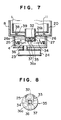
- Figs. 5 and 6 show a third embodiment of the invention.
- This embodiment is distinguished from the first embodiment in that the axial flow pump 30 of the first embodiment is replaced by a centrifugal pump 35 which comprises a spider 32 disposed in and secured to the inner peripheral surface of the cylindrical member 25 to cooperate therewith to define a plurality of fluid passages 33, a plurality of radial vanes 34 each having a rectangular shape and secured to the underside of a hub section of the spider 32, and a restriction disc 36 secured to the bottom end of the cylindrical member 25 and having a central restriction opening 36a of a diameter much smaller than that of the inner periphery of the cylindrical member 25.
- a centrifugal pump 35 which comprises a spider 32 disposed in and secured to the inner peripheral surface of the cylindrical member 25 to cooperate therewith to define a plurality of fluid passages 33, a plurality of radial vanes 34 each having a rectangular shape and secured to the underside of a hub section of the spider 32, and a restriction disc 36 secured to the
- the spider 32 and the radial vanes 34 are rotated together with the cylindrical member 25 to suck the nitric acid solution and the organic solvent from the liquid reservoir 4 through the restriction opening 36a and feed the liquids through the passages 33 up into the rotor 1 while the two kinds of the liquids are agitated and mixed when sucked by the pump.
- This embodiment of the invention is advantageous in that, because the spider 32 is fixed to the inner peripheral surface of the cylindrical member 25, there is little difficulty in establishing, in the process of manufacture, the concentricity of the cylindrical member 25 to the pump impeller.
- the extractor of this embodiment can be made more easily than the extractors of the preceding embodiments. It is needless to say that, in the extractor of this embodiment, the nitric acid solution and the organic solvent both in the reservoir 4 are not splashed through the gap 27 into the annular space 20.
- Figs. 7 and 8 show a fourth embodiment of the invention.
- This embodiment is distinguished from the third embodiment in that a plurality of agitating vanes 37 are mounted on the underside of the restriction disc 36 around the restriction opening 36a, in that the partition 26 is provided on its upper face with an annular projection 38 and in that the partition 26 is formed therein with a plurality of communication apertures 39 disposed radially inwardly of the annular projection 38.
- the upper surface of the partition 26 is radially inwardly and downwardly inclined as at 26b from the communication apertures 39 to the inner peripheral edge of the central opening 26a.
- Figs. 9 and 10 show a modification to the first embodiment described with reference to Figs. 1 and 2.
- This modification is improved over the first embodiment in that an annular horizontal plate 40 and a cylindrical member or ring 42 are disposed in the liquid reservoir 4 concentrically with the cylindrical member 25 for suppressing the formation of waves in the reservoir 4.
- the wave-suppressing plate 40 and the wave-suppressing ring 42 are formed therein with a large number of small apertures 41 and 43.
- these small apertures 41 and 43 impede the flows of the liquids to advantageously eliminate the occurrence or formation of waves which would otherwise be caused by the agitating, mixing and pumping function of the axial flow pump 30.
- the wave-suppressing plate 40 and the wave-suppressing ring 42 are operative to prevent the liquids from being splashed into the annular space 20 between the rotor 1 and the outer housing 8.
- Figs. 11 and 12 show a further embodiment of the invention in which the centrifugal pump 35 shown in Figs. 7 and 8 and the wave-suppressing plate and ring 40 and 42 are incorporated.
- this embodiment has a greater tendency that waves are caused in the liquid reservoir 4 because the agitating vanes 37 are mounted on the underside of the restriction disc 36 of the centrifugal pump 35. This tendency, however, is advantageously eliminated by the wave-suppressing plate 40 and the wave-suppressing ring 42.
Landscapes
- Chemical & Material Sciences (AREA)
- Chemical Kinetics & Catalysis (AREA)
- Extraction Or Liquid Replacement (AREA)
Claims (9)
- Zentrifugalextraktor mit einem äußeren zylindrischen Gehäuse (8), das an seinem unteren Ende mit einem Flüssigkeitsreservoir (4) versehen ist, zur Aufnahme von verschiedenen Arten von zu behandelnden Flüssigkeiten, einem hohlen zylindrischen Rotor (1), der drehbar und koaxial im Gehäuse montiert ist, Pumpenmittel (30; 35) mit einem am unteren Ende der Rotorwelle (6) angeordneten Impeller, der in das Reservoir vorsteht und damit drehbar ist, zum Fördern der Flüssigkeiten von dem Reservoir in den Rotor, wobei die Flüssigkeiten in dem Rotor einer Zentrifugalkraft ausgesetzt sind und durch die Zentrifugalkraft in eine Vielzahl von Flüssigkeitsschichten geteilt werden, und Mittel (15, 16, 17, 18) zum getrennten Abführen der getrennten Flüssigkeitsschichten aus dem Rotor und dem Gehäuse,
dadurch gekennzeichnet,
daß der Impeller der Pumpenmittel von einem zylindrischen hohlen Teil (25) umgeben ist, das mit einer inneren Umfangskante einer Zentralöffnung in der unteren Abschlußwand (11) des Rotors flüssigkeitsdicht verbunden ist und die einzigste Verbindung zwischen dem Inneren des Rotors (1) und dem Flüssigkeitsreservoir (4) darstellt. - Zentrifugalextraktor nach Anspruch 1, dadurch gekennzeichnet, daß eine Trennwand (26) im Boden des Gehäuses (8) zum Trennen des Flüssigkeitsreservoirs von einem Teil des Gehäuses, in dem der Rotor angeordnet ist, vorgesehen ist, wobei die Trennwand mit einer Zentralöffnung (26a) versehen ist, durch die sich das zylindrische Teil (25) von dem Rotor (1) in das Flüssigkeitsreservoir (4) erstreckt, mit einem Spalt (27) mit einer vorbestimmten Öffnungsweite zwischen der inneren Umfangskante der Zentralöffnung (26a) und der äußeren Umfangsfläche des zylindrischen Teils (25).
- Zentrifugalextraktor nach Anspruch 1 oder 2, dadurch gekennzeichnet, daß die Pumpenmittel einen Pumpenschaft (28) enthalten, der mit dem unteren Ende der Rotorwelle (6) verbunden ist, und eine Vielzahl von Schaufeln (29) an der Pumpenwelle befestigt sind.
- Zentrifugalextraktor nach einem der Ansprüche 1-3, dadurch gekennzeichnet, daß mehrere sich bewegende Flügel (31) an die innere Umfangsfläche des zylindrischen Teils (25) befestigt sind.
- Zentrifugalextraktor nach Anspruch 1 oder 2, dadurch gekennzeichnet, daß die Pumpenmittel enthalten ein Kreuzteil (32), das an die innere Umfangsfläche des zylindrischen Teils (25) befestigt ist und damit über Verbindungskanäle (33) in Verbindung steht, mehrere Flügel (34), die mit dem Kreuzteil verbunden sind und ein Teil (36) zur Beschränkung der Öffnungsfläche im unteren Ende des zylindrischen Teils (25).
- Zentrifugalextraktor nach Anspruch 5, dadurch gekennzeichzeichnet, daß das Beschränkungsteil (36) eine Beschränkungsscheibe mit einer zentralen Öffnung (36a) und mehreren sich bewegenden Flügeln (37) enthält, die an der Unterseite der Beschränkungsscheibe um die zentrale Öffnung herum befestigt sind.
- Zentrifugalextraktor nach einem der Ansprüche 2-6, dadurch gekennzeichnet, daß eine ringförmige Vorstehung (38) an der oberen Oberfläche der Trennwand (26) um die darin befindliche zentrale Öffnung (26a) herum vorgesehen ist und in der Trennwand Verbindungsöffnungen (39) gebildet sind, die radial innerhalb der ringförmigen Vorstehung (38) angeordnet sind.
- Zentrifugalextraktor nach Anspruch 7, dadurch gekennzeichnet, daß die obere Oberfläche der Trennwand (26) von den Verbindungsöffnungen (39) zu der Zentralöffnung (26a) der Trennwand nach unten geneigt ist.
- Zentrifugalextraktor nach einem der Ansprüche 1-5, dadurch gekennzeichnet, daß kreisförmige Mittel (40, 42) zur Wellenunterdrückung mit einer großen Anzahl von darin gebildeten Öffnungen (41, 43) in dem Reservoir (4) konzentrisch zu dem zylindrischen Teil (25) angeordnet sind.
Applications Claiming Priority (2)
| Application Number | Priority Date | Filing Date | Title |
|---|---|---|---|
| JP62258086A JPH0199605A (ja) | 1987-10-13 | 1987-10-13 | 遠心抽出機 |
| JP258086/87 | 1987-10-13 |
Publications (2)
| Publication Number | Publication Date |
|---|---|
| EP0312045A1 EP0312045A1 (de) | 1989-04-19 |
| EP0312045B1 true EP0312045B1 (de) | 1992-02-19 |
Family
ID=17315324
Family Applications (1)
| Application Number | Title | Priority Date | Filing Date |
|---|---|---|---|
| EP19880117014 Expired EP0312045B1 (de) | 1987-10-13 | 1988-10-13 | Zentrifugalextraktor |
Country Status (3)
| Country | Link |
|---|---|
| EP (1) | EP0312045B1 (de) |
| JP (1) | JPH0199605A (de) |
| DE (1) | DE3868479D1 (de) |
Families Citing this family (11)
| Publication number | Priority date | Publication date | Assignee | Title |
|---|---|---|---|---|
| JPH0775643B2 (ja) * | 1990-12-18 | 1995-08-16 | 動力炉・核燃料開発事業団 | 内部循環型遠心抽出器 |
| US6363611B1 (en) * | 1998-11-16 | 2002-04-02 | Costner Industries Nevada, Inc. | Method of making an easily disassembled rotor assembly for a centrifugal separator |
| FR2831112B1 (fr) | 2001-10-24 | 2004-01-23 | Inergy Automotive Systems Man | Reservoir a carburant et procede de fabrication de ce reservoir |
| FR2831113B1 (fr) | 2001-10-24 | 2004-01-02 | Inergy Automotive Systems Man | Systeme et procede d'obturation d'une ouverture d'un reservoir |
| FR2841485B1 (fr) * | 2002-07-01 | 2004-08-06 | Commissariat Energie Atomique | Extracteur centrifuge annulaire a rotor d'agitation noye |
| CN103830933B (zh) * | 2014-03-24 | 2015-12-16 | 靖江市鼎鑫矿山设备有限公司 | 圆筒式离心萃取机 |
| EP2946836B1 (de) | 2014-05-23 | 2020-02-19 | Alfa Laval Corporate AB | Zentrifugalabscheider |
| CN106955794B (zh) * | 2017-05-16 | 2023-02-21 | 郑州天一萃取科技有限公司 | 一种离心萃取机用双转鼓结构 |
| CN107281777A (zh) * | 2017-08-11 | 2017-10-24 | 上海弗鲁克科技发展有限公司 | 在线破碎萃取反应器 |
| CN111991844B (zh) * | 2020-07-29 | 2021-04-27 | 珠海市标定检测技术有限公司 | 一种具有自动萃取和取液功能的萃取装置及萃取方法 |
| CN111921229B (zh) * | 2020-10-14 | 2020-12-25 | 南昌市第三中学 | 萃取装置 |
-
1987
- 1987-10-13 JP JP62258086A patent/JPH0199605A/ja active Pending
-
1988
- 1988-10-13 DE DE8888117014T patent/DE3868479D1/de not_active Expired - Lifetime
- 1988-10-13 EP EP19880117014 patent/EP0312045B1/de not_active Expired
Also Published As
| Publication number | Publication date |
|---|---|
| JPH0199605A (ja) | 1989-04-18 |
| DE3868479D1 (de) | 1992-03-26 |
| EP0312045A1 (de) | 1989-04-19 |
Similar Documents
| Publication | Publication Date | Title |
|---|---|---|
| EP0312045B1 (de) | Zentrifugalextraktor | |
| JP3000530B2 (ja) | 遠心分離機の回転子囲い板 | |
| US3332614A (en) | Centrifugal extractor | |
| US5267936A (en) | Multi-stage centrifugal extractors for separating liquids of differing densities wherein recycling of portions of the separated liquids occurs at each stage | |
| JPH07107398B2 (ja) | 遠心ポンプ | |
| US5254075A (en) | Internal circulation type centrifugal extractor | |
| JPS6355985B2 (de) | ||
| US4824430A (en) | High-speed centrifugal extractor having spiral liquid path | |
| JPH0568294B2 (de) | ||
| JPH0753955B2 (ja) | ガス排出装置 | |
| US3365128A (en) | Industrial process and apparatus | |
| JPH08309172A (ja) | 液体処理装置 | |
| US5453192A (en) | Multistage centrifugal extractor | |
| JPS6238002B2 (de) | ||
| CN210251336U (zh) | 离心式脱气机 | |
| JPH01274805A (ja) | 遠心抽出機 | |
| US4367202A (en) | Centrifugal counter-flow liquid contactor | |
| CN220610832U (zh) | 一种兼有搅拌混合和离心功能的离心机 | |
| CN210251334U (zh) | 离心式脱气机的进料结构和离心式脱气机 | |
| CN210251335U (zh) | 离心式脱气机的叶轮和离心式脱气机 | |
| CN116920451A (zh) | 一种离心萃取机的出料单元及离心萃取机 | |
| US20240238697A1 (en) | Annular Centrifugal Extractor with Solid Separation Part to Separate Solid Particles Present in Solvent Extraction Fluid and a Process for the Same | |
| CN213393543U (zh) | 一种离心机轴颈的密封结构 | |
| RU2802118C1 (ru) | Устройство для разделения масловоздушной смеси двигателя внутреннего сгорания | |
| CN211748826U (zh) | 一种压力锅及其压力释放装置 |
Legal Events
| Date | Code | Title | Description |
|---|---|---|---|
| PUAI | Public reference made under article 153(3) epc to a published international application that has entered the european phase |
Free format text: ORIGINAL CODE: 0009012 |
|
| AK | Designated contracting states |
Kind code of ref document: A1 Designated state(s): DE FR GB |
|
| 17P | Request for examination filed |
Effective date: 19890816 |
|
| 17Q | First examination report despatched |
Effective date: 19910522 |
|
| GRAA | (expected) grant |
Free format text: ORIGINAL CODE: 0009210 |
|
| AK | Designated contracting states |
Kind code of ref document: B1 Designated state(s): DE FR GB |
|
| REF | Corresponds to: |
Ref document number: 3868479 Country of ref document: DE Date of ref document: 19920326 |
|
| ET | Fr: translation filed | ||
| PGFP | Annual fee paid to national office [announced via postgrant information from national office to epo] |
Ref country code: FR Payment date: 19920814 Year of fee payment: 5 |
|
| PGFP | Annual fee paid to national office [announced via postgrant information from national office to epo] |
Ref country code: GB Payment date: 19921002 Year of fee payment: 5 |
|
| PLBE | No opposition filed within time limit |
Free format text: ORIGINAL CODE: 0009261 |
|
| STAA | Information on the status of an ep patent application or granted ep patent |
Free format text: STATUS: NO OPPOSITION FILED WITHIN TIME LIMIT |
|
| PGFP | Annual fee paid to national office [announced via postgrant information from national office to epo] |
Ref country code: DE Payment date: 19921223 Year of fee payment: 5 |
|
| 26N | No opposition filed | ||
| PG25 | Lapsed in a contracting state [announced via postgrant information from national office to epo] |
Ref country code: GB Effective date: 19931013 |
|
| GBPC | Gb: european patent ceased through non-payment of renewal fee |
Effective date: 19931013 |
|
| PG25 | Lapsed in a contracting state [announced via postgrant information from national office to epo] |
Ref country code: FR Effective date: 19940630 |
|
| PG25 | Lapsed in a contracting state [announced via postgrant information from national office to epo] |
Ref country code: DE Effective date: 19940701 |
|
| REG | Reference to a national code |
Ref country code: FR Ref legal event code: ST |