EP0311806B1 - Ablenkeinheit für Farbkathodenstrahlvorrichtung - Google Patents
Ablenkeinheit für Farbkathodenstrahlvorrichtung Download PDFInfo
- Publication number
- EP0311806B1 EP0311806B1 EP88115045A EP88115045A EP0311806B1 EP 0311806 B1 EP0311806 B1 EP 0311806B1 EP 88115045 A EP88115045 A EP 88115045A EP 88115045 A EP88115045 A EP 88115045A EP 0311806 B1 EP0311806 B1 EP 0311806B1
- Authority
- EP
- European Patent Office
- Prior art keywords
- deflection
- horizontal
- vertical
- magnetic field
- electron beams
- Prior art date
- Legal status (The legal status is an assumption and is not a legal conclusion. Google has not performed a legal analysis and makes no representation as to the accuracy of the status listed.)
- Expired - Lifetime
Links
Images


Classifications
-
- H—ELECTRICITY
- H01—ELECTRIC ELEMENTS
- H01J—ELECTRIC DISCHARGE TUBES OR DISCHARGE LAMPS
- H01J29/00—Details of cathode-ray tubes or of electron-beam tubes of the types covered by group H01J31/00
- H01J29/46—Arrangements of electrodes and associated parts for generating or controlling the ray or beam, e.g. electron-optical arrangement
- H01J29/70—Arrangements for deflecting ray or beam
- H01J29/72—Arrangements for deflecting ray or beam along one straight line or along two perpendicular straight lines
- H01J29/76—Deflecting by magnetic fields only
-
- H—ELECTRICITY
- H04—ELECTRIC COMMUNICATION TECHNIQUE
- H04N—PICTORIAL COMMUNICATION, e.g. TELEVISION
- H04N9/00—Details of colour television systems
- H04N9/12—Picture reproducers
- H04N9/16—Picture reproducers using cathode ray tubes
- H04N9/28—Arrangements for convergence or focusing
-
- H—ELECTRICITY
- H01—ELECTRIC ELEMENTS
- H01J—ELECTRIC DISCHARGE TUBES OR DISCHARGE LAMPS
- H01J2229/00—Details of cathode ray tubes or electron beam tubes
- H01J2229/96—Circuit elements other than coils, reactors or the like, associated with the tube
- H01J2229/964—Circuit elements other than coils, reactors or the like, associated with the tube associated with the deflection system
Definitions
- the present invention relates to a color cathode-ray tube and, more particularly, to a color cathode-ray tube which has a deflection unit improved such that three electron beams are converged accurately on a screen and neither a negative cross pattern nor a positive cross pattern will appear on any part of the screen.
- color cathode-ray tubes having a shadow mask the most prevailing one is the type which comprises an in-line electron gun assembly having three electron guns, and a shadow mask having slot-like apertures.
- the color cathode-ray tube of this type has a deflection yoke which is designed to generate such horizontal and vertical deflection magnetic fields that the red, green and blue electron beams pass through an aperture at the same time.
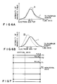
- deflection magnetic fields are known, as is disclosed in, for example, Japanese Patent Disclosure No. 57-1857. More specifically, the horizontal deflection magnetic field is shaped like a pin-cushion as is shown in Fig. 1A, and the vertical deflection magnetic field is shaped like a barrel as is illustrated in Fig. 1B.
- the cathode-ray tube When the cathode-ray tube has a relatively small deflection angle, these magnetic fields deflect the three electron beams correctly, thus achieving good beam-convergence on any part of the screen. Therefore, the tube need not have a device for correcting the beam-convergence.
- the cathode-ray tube has a great deflection angle, e.g., 100° or 110°, however, a convergence error, which is generally called "crossing of vertical lines,” will occur. It is regarded as impossible to correct this convergence error even if the horizontal and vertical deflection magnetic fields are changed in characteristic, as is disclosed in Iwasaki et al.
- the saddle coil for deflecting the electron beams horizontally have a center of deflection located closer to the electron guns than the center of deflection of the toroidal coil for deflecting the beams vertically. If the centers of deflections of both coils take the same position, a convergence error, generally known as a positive cross pattern (Fig. 2A), will be made. The positive cross pattern is corrected into such a neutral one as is shown in Fig. 2C when the center of deflection of the saddle coil is deviated toward the electron guns from the center of deflection of the toroidal coil.
- a positive cross pattern nor a negative cross pattern appear on the horizontal axis, at point P0 in the region near this axis, or at points P2 in the corner regions when the positional relation of the horizontal deflection coil and the vertical deflection coil is properly adjusted.
- a positive cross pattern and a negative cross pattern are formed at other points, such as a point P1 between the horizontal axis and any corner region, or a point P3 located at the outer edge of any corner, even if the positional relation of the coils is adjusted.
- the cross patterns appearing at point P1 and the outer edge of the corner are inverted. This inversion of cross patterns is prominent in proportion to the deflection angle or the size of the screen. Therefore, in the conventional color cathode-ray, a magnetic plate or the like is attached to the deflection yoke in order to reduce the chance of forming positive and negative cross patterns. The use of the magnetic plate, however, does not reduce said chance sufficiently.
- Document EP-A-0 283 904 discloses a color cathode ray tube apparatus comprising an evacuated envelope having a tube axis Z, a phosphor screen, an electron gun assembly and deflection magnetic field generating means.
- the phosphor screen is formed in the envelope , wherein the tube axis Z passes through a center of the phosphor screen, and has horizontal and vertical axes X and Y orthogonal to the tube axis Z.
- the electron gun assembly is an in-line type electron gun assembly and arranged in the evacuated envelope, for emitting a central beam, and side beams, toward the phosphor screen, the electron beams being landed on said phosphor screen to cause the phosphor screen to emit light rays.
- the deflection magnetic field generating means are arranged outside the evacuated envelope, for generating horizontal and vertical deflection magnetic fields inside the envelope so as to horizontally and vertically deflect the electron beams and scan the phosphor screen with the electron beams.
- the horizontal deflection magnetic field includes a main deflection magnetic field having a barrel-shaped distribution and composed of a vertical component formed in the envelope so as to be symmetrical about a Y-Z plane including Y-and Z-axes and extend along the Y-axis, and an auxiliary deflection magnetic field substantially antisymmetric about the Y-Z plane including the Y- and Z-axes and mainly composed of a vertical component.
- the object of the present invention is to provide a color cathode-ray apparatus which has a good convergence characteristic.
- the present invention provides a color cathode-ray apparatus as specified in anyone of claims 1, 7 and 8.
- Figs. 4 and 5 schematically illustrate a color cathode-ray tube according to the present invention.
- the color cathode-ray tube comprises an envelope, in-line electron gun assembly 10 incorporated in the envelope, and shadow mask 3 provided within the envelope.
- the envelope of this tube has a face plate 1 and a phosphor screen 2 formed on the inner surface of the plate 1.
- the screen 2 consists of dot-shaped or stripe-shaped phosphor layers which are arranged orderly. These phosphor layers emit red, green and blue light rays when the electron beams emitted from the electron gun assembly are applied to them.
- a mask frame 4 supports a shadow mask 3, forming a predetermined gap between the phosphor screen 2 and the shadow mask 3.
- the shadow mask 3 has a number of apertures 12.
- An inner shield 14 is fastened to the mask frame 4.
- a funnel 7, which is a part of the envelope, is connected to the skirt 1-1 of the face plate 1.
- a neck 9, which is also a part of the envelope, extends from the funnel 7.
- An electron gun assembly 10 is arranged within the neck 9.
- a deflection unit 8 is mounted on the neck 9. More specifically, the deflection unit 8 is fastened to the neck 9 by means of a support 8-1 and steadily mounted on the funnel 7 by means of wedges 8-2.
- a ring-shaped magnet 11 is also mounted on the neck 9.
- the electron gun assembly 10 has three electron guns for emitting a red electron beam, a green electron beam, and a red electron beam, respectively, toward the phosphor screen 2.
- the three electron guns are arranged side by side in horizontal direction, thus forming an in-line gun assembly which is predominantly used in color cathode-ray tubes generally called "three-beam, shadow mask tubes.”
- the gun assembly 10 is designed to apply the red, green and blue beams onto the same point on the phosphor screen 2.
- the deflection unit 8 is designed to generate a magnetic field which causes the three electron beams to pass through the same aperture of the shadow mask 3.
- the deflection unit 8 (i.e., a deflection yoke) comprises one toroidal coil 15 and two saddle coils 16 and 17.
- the toroidal coil 15, which functions as a vertical deflection coil, is formed of ferrite core 18 and a wire wound around core 18. It generates a magnetic field whose intensity is distributed as indicated by a curve I in Fig. 6A and 6B.
- the saddle coil 17 is mounted partly on the funnel 7 and partly on the neck 9; the saddle coil 16 is mounted on the coil 17; and the toroidal coil 15 is mounted on the coil 16.
- the first saddle coil 16 is so designed that a combination of this coil 16 and the toroidal coil 15 has a positive cross convergence characteristic. More specifically, the saddle coil 16 generates a pincushion magnetic field. When this magnetic field interacts with the magnetic field generated by the toroidal coil 15, the positive cross convergence characteristic shown in Fig. 2A will be obtained.
- the deflection center C1 of the horizontal deflection magnetic field (curve II in Fig. 6A) generated by the first saddle coil 16 is located further to the electron gun assembly 10 than the deflection center C0 of the vertical deflection magnetic field (curve I in Figs. 6A and 6B) generated by the toroidal coil 15.
- the second saddle coil 17 is so designed that a combination of this coil 17 and the toroidal coil 15 has a negative cross convergence characteristic. More specifically, the saddle coil 17 generates a barrel magnetic field. When this magnetic field interacts with the magnetic field generated by the toroidal coil 15, the negative cross convergence characteristic shown in Fig. 2B will be obtained.
- the deflection center C2 of the horizontal deflection magnetic field (curve III in Fig. 6A) generated by the second saddle coil 17 is located closer to the electron gun assembly 10 than the deflection center C1 of the horizontal deflection magnetic field generated by the first saddle coil 16, with respect to the center C0 of the vertical deflection magnetic field (curve I in Figs. 6A and 6B) generated by the toroidal coil 15.
- the deflection unit 8 which is constituted by the toroidal coil 15 (i.e., a vertical deflection coil), the first saddle coil 16 (i.e., a horizontal deflection coil), and the second saddle coil 17 (i.e., a horizontal deflection coil), has the specific cross convergence characteristic shown in Fig. 3, when the same deflection current is supplied to both saddle coils 16 and 17.
- the first saddle coil 16 generates a pincushion magnetic field
- the second saddle coil 17 generates a barrel magnetic field. These magnetic fields are combined, thus eliminating the convergence error on the horizontal axis of the phosphor screen 2, as is illustrated in Fig. 7.
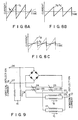
- deflection currents I B and I C whose waveforms are shown in Figs. 8A, 8B and 8C, are supplied from a deflection current source 20 to the first and second saddle coils 16 and 17, respectively. More specifically, to deflect the electrons beams vertically and thereby apply them to a point P1 located between the horizontal axis of the screen 2 and a corner of the screen 2 (Fig.
- currents I B and I C are applied to the coils 16 and 17, wherein
- currents I B and I C are supplied to the coils 16 and 17, where
- Fig. 9 is a circuit diagram of the deflection current source 20.
- Vertical deflection current I A is supplied to input terminals 26 and 27.
- Saturable reactors 24 and 25 are provided whose reactance can be adjusted and whose saturation points can be adjusted by permanent magnets 28 and 29. The primary ends of these reactors 24 and 25 are connected between input terminals 26 and 27, on the one hand, and the vertical deflection coil 15, on the other.
- Horizontal deflection current I0 is supplied to input terminals 22 and 23.
- the horizontal deflection coil 16, which consists of two coils, is connected in parallel to the input terminals 22 and 23.
- the horizontal deflection coil 17, also consisting of two coils, is coupled in parallel to the input terminals 22 and 23.
- the secondary ends of the reactors 24 and 25 are connected between the horizontal deflection coils 16 and 17, on the one hand, and the input terminal 22, on the other hand. Therefore, current I0 is modulated by vertical deflection current I A , and currents I B and I C (Figs. 8B and 8C) are supplied to the horizontal deflection coils 16 and 17, respectively. Currents I B and I C are changed in accordance with the degree of vertical deflection of the electron beams, and the convergence error is corrected in accordance with the positions on the screen 2 where the beams are applied. As a result, neither a positive cross pattern nor a negative cross pattern is formed on the screen 2.
- the circuit shown in Fig. 9 can be replaced by a similar circuit having saturable reactors. Further, saturable reactors 24 and 25 can be modulated by the magnetic flux leaking from the vertical deflection coil 15, not by the vertical deflection current. It is also possible that two horizontal deflection currents I B and I C can be supplied from two independent current sources. Moreover, various circuit elements can be utilized to adjust the reactances of the saturable reactors 24 and 25.
- the first saddle coil 16 is wrapped around almost the entire second saddle coil 17.
- the coil 16 can be positioned so that only its rear end portion surrounds the second saddle coil 17.
- the vertical deflection coil 15, which is a toroidal coil can be replaced by a saddle coil.
- Fig. 11 shows another deflection unit 8 according to the present invention.
- This deflection unit comprises one horizontal deflection coil 119 and two vertical deflection coils 120 and 121. These coils 119, 120 and 121 are saddle coils. The coils 120 and 121 generate vertical deflection magnetic fields which have different centers of deflection. The deflection center of the coil 120 is defined between the coil 121 and the electron gun assembly 10.
- the combination of the coils 120 and 119 exhibits a positive cross convergence characteristic shown in Fig. 2A, whereas the combination of the coil 121 and the coil 119 presents the negative cross convergence characteristic shown in Fig. 2B. Further, the combination of the coils 119, 120 and 121 will have the cross convergence characteristic shown in Fig.
- the horizontal deflection coil 119 generates a magnetic field which is either uniform or a slightly pincushion-shaped.
- the first vertical deflection coil 120 generates a pincushion magnetic field.
- the second vertical deflection coil 121 generates a barrel magnetic field.
- a deflection current source 130 supplies deflection currents I F , I D and I E to the horizontal deflection coil 119, the first vertical deflection coil 120, and the second vertical deflection coil 121, respectively.
- Currents I D and I E have such waveforms as shown in Fig. 12.
- current I D is smaller than current I E , whereby the positive cross pattern is eliminated.
- current I E is smaller than current I D , whereby the negative cross pattern is eliminated.
- a good convergence characteristic is achieved all over the screen 2.
- Fig. 13 shows a modification of the deflection current source 130 (Fig. 11).
- the deflection current supplied to input terminals 26 and 27 is converted into currents I D and I E having the waveforms illustrated in Fig. 12, due to the non-linear current-voltage characteristic of diodes D1 to D4.
- Deflection currents I D and I E are supplied to the first vertical coil 120 and the second vertical coil 121, respectively.
- Currents I E and I D can be adjusted by changing the resistances of variable resistors R1 to R4.
- the centers of deflection of the deflection magnetic fields are shifted, and the distribution of intensity of these fields is changed.
- the centers of deflection and the distribution of intensity are determined by the desired loci of the electron beams.
- the centers of deflections are identical with the centers of gravity of the coils, or with the positions where the magnetic fields are most intense, in most color cathode-ray tubes.
- the embodiment described above uses a combination of coils which are different both in intensity distribution and in center of deflection.
- a combination of coils which are different in only intensity distribution or only in magnetic field shape such as barrel and pincushion can be used, though these coils can correct a cross convergence error less effectively than that described up to here.
- the first and second horizontal deflection coils generate a pincushion magnetic field and a barrel magnetic field, the changes in the horizontal deflection currents flowing in these coils are minimized during the vertical deflection period. Hence, these current can be modulated easily.
- the distance between the center of deflection of the horizontal deflection coils is short, it is easy to manufacture the deflection unit (i.e., the deflection yoke).
- the "center of deflection" of any coil used in the invention may be regarded as either the center of gravity of the coil or the point where the deflection magnetic field generated by the coil is most intense.
- the color cathode-ray apparatus according to the present invention has a good convergence characteristic all over the phosphor screen, and it is greatly useful from an industrial point of view.
Claims (8)
- Farbkathodenstrahlvorrichtung, welche folgendes umfaßt:- einen evakuierten Röhrenkolben (1, 7, 9) mit einer Röhrenachse sowie einer die Röhrenachse im rechten Winkel und einander im rechten Winkel schneidenden horizontalen und vertikalen Achse;- einen im evakuierten Röhrenkolben integrierten Leuchtschirm;- eine Inline-Elektronenspritzeneinheit (10) zur Emission dreier Elektronenstrahlen in Richtung dieses Leuchtschirms (2);- eine horizontale Ablenkeinrichtung (119) zur Erzeugung eines horizontalen Ablenkmagnetfeldes zur Ablenkung der Elektronenstrahlen entlang der horizontalen Achse;- eine vertikale Ablenkeinrichtung (120, 121) zur Erzeugung eines vertikalen Ablenkmagnetfeldes zur Ablenkung der Elektronenstrahlen entlang der vertikalen Achse; und- eine Stromversorgungseinrichtung (130) zur Lieferung horizontaler und vertikaler Ablenkströme an die horizontale und vertikale Ablenkeinrichtung (119, 120, 121), um die horizontale und vertikale Ablenkeinrichtung (119, 120, 121) zu erregen;
dadurch gekennzeichnet, daß
die vertikale Ablenkeinrichtung (120, 121) eine erste Ablenkspule (120) mit einem ersten Ablenkmittelpunkt zur Erzeugung eines ersten Magnetfeldes und eine zweite Ablenkspule (121) mit einem zweiten Ablenkmittelpunkt zur Erzeugung eines zweiten Magnetfeldes enthält, wobei der erste und zweite Ablenkmittelpunkt in verschiedenen Punkten der Röhrenachse liegen, der erste Ablenkmittelpunkt zwischen dem zweiten Ablenkmittelpunkt und der Elektronenspritzeneinheit definiert ist, die Stromversorgungseinrichtung (130) einen ersten vertikalen Ablenkstrom und einen zweiten vertikalen Ablenkstrom an die erste bzw. zweite Ablenkspule (120 bzw. 121) liefert und der erste und zweite vertikale Ablenkstrom auf verschiedene Weise, entsprechend einem Winkel, in welchem die Elektronenstrahlen in vertikaler Richtung abzulenken sind, geändert werden. - Farbkathodenstrahlvorrichtung gemäß Anspruch 1, dadurch gekennzeichnet, daß der Leuchtschirm (2) Eckenzonen mit jeweils einem Außenrand und Zwischenzonen zwischen der horizontalen Achse und den Eckenzonen aufweist, und der erste und zweite vertikale Ablenkstrom gleich groß sind, um die Elektronenstrahlen auf einen vorgegebenen Punkt in jeder Eckenzone zu richten.
- Farbkathodenstrahlvorrichtung gemäß Anspruch 2, dadurch gekennzeichnet, daß der Absolutwert des ersten vertikalen Ablenkstroms kleiner ist als derjenige des zweiten vertikalen Ablenkstroms, um die Elektronenstrahlen auf einen vorgegebenen Punkt in jeder Zwischenzone zu richten.
- Farbkathodenstrahlvorrichtung gemäß Anspruch 3, dadurch gekennzeichnet, daß der Absolutwert des ersten vertikalen Ablenkstroms größer ist als derjenige des zweiten vertikalen Ablenkstroms, um die Elektronenstrahlen auf den Außenrand jeder Eckenzone zu richten.
- Farbkathodenstrahlvorrichtung gemäß Anspruch 3, dadurch gekennzeichnet, daß die horizontale Ablenkreinrichtung (119) ein Magnetfeld von entweder gleichmäßiger oder leicht kissenartiger Form erzeugt.
- Farbkathodenstrahlvorrichtung gemäß Anspruch 1, dadurch gekennzeichnet, daß das erste Magnetfeld vom Kissentyp und das zweite Magnetfeld vom Tonnentyp ist.
- Farbkathodenstrahlvorrichtung, welche folgendes umfaßt:- einen evakuierten Röhrenkolben (1, 7, 9) mit einer Röhrenachse sowie einer die Röhrenachse im rechten Winkel und einander im rechten Winkel schneidenden horizontalen und vertikalen Achse;- einen im evakuierten Röhrenkolben integrierten Leuchtschirm;- eine Inline-Elektronenspritzeneinheit (10) zur Emission dreier Elektronenstrahlen in Richtung dieses Leuchtschirms (2);- eine vertikale Ablenkeinrichtung (15) zur Erzeugung eines vertikalen Ablenkmagnetfeldes zur Ablenkung der Elektronenstrahlen entlang der vertikalen Achse;- eine horizontale Ablenkeinrichtung (16, 17) zur Erzeugung eines horizontalen Ablenkmagnetfeldes zur Ablenkung der Elektronenstrahlen entlang der horizontalen Achse; und- eine Stromversorgungseinrichtung (20) zur Lieferung vertikaler und horizontaler Ablenkströme an die vertikale und horizontale Ablenkeinrichtung (15, 16, 17), um die vertikale und horizontale Ablenkeinrichtung (119, 120, 121) zu erregen; in welcher
die horizontale Ablenkeinrichtung (16, 17) eine erste Ablenkspule (16) mit einem ersten Ablenkmittelpunkt zur Erzeugung eines ersten Magnetfeldes und eine zweite Ablenkspule (17) mit einem zweiten Ablenkmittelpunkt zur Erzeugung eines zweiten Magnetfeldes enthält, wobei der erste und zweite Ablenkmittelpunkt in verschiedenen Punkten der Röhrenachse liegen, der zweite Ablenkmittelpunkt zwischen dem ersten Ablenkmittelpunkt und der Elektronenspritzeneinheit definiert ist, die Stromversorgungseinrichtung (20) einen ersten horizontalen Ablenkstrom (IB) und einen zweiten horizontalen Ablenkstrom (IC) an die erste bzw. zweite Ablenkspule (16 bzw. 17) liefert und der erste und zweite horizontale Ablenkstrom (IB , IC) auf verschiedene Weise, entsprechend einem Winkel, in welchem die Elektronenstrahlen in horizontaler Richtung abzulenken sind, geändert werden, und wobei der Leuchtschirm (2) Eckenzonen mit jeweils einem Außenrand und Zwischenzonen zwischen der horizontalen Achse und den Eckenzonen aufweist,
dadurch gekennzeichnet, daß
der erste und zweite horizontale Ablenkstrom (IB , IC) gleich groß sind, um die Elektronenstrahlen auf einen vorgegebenen Punkt in jeder Eckenzone zu richten, der Absolutwert des ersten horizontalen Ablenkstroms (IB) kleiner ist als derjenige des zweiten horizontalen Ablenkstroms (IC), um die Elektronenstrahlen auf einen vorgegebenen Punkt in jeder Zwischenzone zu richten, der Absolutwert des ersten horizontalen Ablenkstroms (IB) größer ist als derjenige des zweiten horizontalen Ablenkstroms (IC), um die Elektronenstrahlen auf den Außenrand jeder Eckenzone zu richten,
die vertikale Ablenkreinrichtung (15) ein Magnetfeld von entweder gleichmäßiger oder leicht kissenartiger Form erzeugt, und
das erste Magnetfeld vom Kissentyp und das zweite Magnetfeld vom Tonnentyp ist. - Farbkathodenstrahlvorrichtung, welche folgendes umfaßt:- einen evakuierten Röhrenkolben (1, 7, 9) mit einer Röhrenachse sowie einer die Röhrenachse im rechten Winkel und einander im rechten Winkel schneidenden horizontalen und vertikalen Achse;- einen im evakuierten Röhrenkolben integrierten Leuchtschirm;- eine Inline-Elektronenspritzeneinheit (10) zur Emission dreier Elektronenstrahlen in Richtung dieses Leuchtschirms (2);- eine vertikale Ablenkeinrichtung (15, 120, 121) zur Erzeugung eines vertikalen Ablenkmagnetfeldes zur Ablenkung der Elektronenstrahlen entlang der vertikalen Achse;- eine horizontale Ablenkeinrichtung (16, 17, 119) zur Erzeugung eines horizontalen Ablenkmagnetfeldes zur Ablenkung der Elektronenstrahlen entlang der horizontalen Achse; und- eine Stromversorgungseinrichtung (20) zur Lieferung vertikaler und horizontaler Ablenkströme an die vertikale und horizontale Ablenkeinrichtung (15, 16, 17, 119, 120, 121), um die vertikale und horizontale Ablenkeinrichtung (15, 16, 17, 119, 120, 121) zu erregen;
dadurch gekennzeichnet, daß
eine der vertikalen und horizontalen Ablenkeinrichtungen (15, 120, 121; 16, 17, 119) eine erste Ablenkspule (16, 120) zur Erzeugung eines Tonnenmagnetfeldes und eine zweite Ablenkspule (17, 121) zur Erzeugung eines Kissenmagnetfeldes enthält, die Stromversorgungseinrichtung (20) einen ersten und zweiten Ablenkstrom an die erste und zweite Ablenkeinrichtung (16, 17, 120, 121) liefert und die Ablenkströme auf verschiedene Weise, entsprechend einem Winkel, in welchem die Elektronenstrahlen abzulenken sind, geändert werden.
Applications Claiming Priority (4)
| Application Number | Priority Date | Filing Date | Title |
|---|---|---|---|
| JP229453/87 | 1987-09-16 | ||
| JP62229453A JP2597596B2 (ja) | 1987-09-16 | 1987-09-16 | カラー受像管装置 |
| JP10270888A JP2685797B2 (ja) | 1988-04-27 | 1988-04-27 | カラー映像管装置 |
| JP102708/88 | 1988-04-27 |
Publications (2)
| Publication Number | Publication Date |
|---|---|
| EP0311806A1 EP0311806A1 (de) | 1989-04-19 |
| EP0311806B1 true EP0311806B1 (de) | 1994-02-16 |
Family
ID=26443381
Family Applications (1)
| Application Number | Title | Priority Date | Filing Date |
|---|---|---|---|
| EP88115045A Expired - Lifetime EP0311806B1 (de) | 1987-09-16 | 1988-09-14 | Ablenkeinheit für Farbkathodenstrahlvorrichtung |
Country Status (5)
| Country | Link |
|---|---|
| US (1) | US4881015A (de) |
| EP (1) | EP0311806B1 (de) |
| KR (1) | KR910009662B1 (de) |
| CN (1) | CN1023926C (de) |
| DE (1) | DE3887808T2 (de) |
Families Citing this family (6)
| Publication number | Priority date | Publication date | Assignee | Title |
|---|---|---|---|---|
| US5177412A (en) * | 1989-05-26 | 1993-01-05 | Kabushiki Kaisha Toshiba | Color cathode ray tube apparatus |
| TW258850B (de) * | 1992-03-09 | 1995-10-01 | Samsung Electronic Devices | |
| US5650628A (en) * | 1994-12-15 | 1997-07-22 | International Business Machines Corporation | Simultaneous deflections in charged-particle beams |
| JP2000277037A (ja) * | 1999-03-29 | 2000-10-06 | Sony Corp | 偏向ヨークおよび陰極線管 |
| JP2001256904A (ja) * | 2000-03-08 | 2001-09-21 | Sony Corp | 偏向装置及び陰極線管装置並びにビームランディング調整方法 |
| EP1139379A3 (de) * | 2000-03-29 | 2004-02-04 | Matsushita Display Devices (Germany) GmbH | Farbbildröhre mit verringertem Abbildungsfehler |
Citations (1)
| Publication number | Priority date | Publication date | Assignee | Title |
|---|---|---|---|---|
| EP0283904A1 (de) * | 1987-03-16 | 1988-09-28 | Kabushiki Kaisha Toshiba | Farbkathodenstrahlrohreinrichtung |
Family Cites Families (11)
| Publication number | Priority date | Publication date | Assignee | Title |
|---|---|---|---|---|
| BE754746A (fr) * | 1969-08-13 | 1971-01-18 | Ford Motor Co | Procede pour augmenter la puissance de sortie d'un accelerateurelectronique |
| JPS5230113A (en) * | 1975-09-02 | 1977-03-07 | Sony Corp | Deflecting device of in-line type color cathode-ray tube |
| JPS5942415B2 (ja) * | 1976-01-26 | 1984-10-15 | ソニー株式会社 | インライン形カラ−陰極線管の偏向装置 |
| JPS55115243A (en) * | 1979-02-27 | 1980-09-05 | Toshiba Corp | Deflector |
| JPS57145254A (en) * | 1981-03-02 | 1982-09-08 | Victor Co Of Japan Ltd | Electromagnetic deflecting coil |
| CA1173977A (en) * | 1981-03-31 | 1984-09-04 | Electrohome Limited | Regulation of the scan width of a raster scanned crt deflection system |
| JPS57206184A (en) * | 1981-06-14 | 1982-12-17 | Victor Co Of Japan Ltd | Picture correcting device for in-line type color picture tube |
| JPS5814453A (ja) * | 1981-07-17 | 1983-01-27 | Victor Co Of Japan Ltd | カラ−受像管の偏向装置 |
| JPS60125069A (ja) * | 1983-12-12 | 1985-07-04 | Victor Co Of Japan Ltd | インライン型カラ−受像管の画像補正装置 |
| JPS6223695A (ja) * | 1985-07-24 | 1987-01-31 | Victor Co Of Japan Ltd | コンバ−ゼンス補正装置 |
| CA1269694A (en) * | 1985-07-31 | 1990-05-29 | Paul Michael Bruey | Deflection distortion correction device |
-
1988
- 1988-09-14 EP EP88115045A patent/EP0311806B1/de not_active Expired - Lifetime
- 1988-09-14 DE DE3887808T patent/DE3887808T2/de not_active Expired - Fee Related
- 1988-09-15 CN CN88106725A patent/CN1023926C/zh not_active Expired - Fee Related
- 1988-09-15 US US07/244,824 patent/US4881015A/en not_active Expired - Lifetime
- 1988-09-16 KR KR1019880012062A patent/KR910009662B1/ko not_active IP Right Cessation
Patent Citations (1)
| Publication number | Priority date | Publication date | Assignee | Title |
|---|---|---|---|---|
| EP0283904A1 (de) * | 1987-03-16 | 1988-09-28 | Kabushiki Kaisha Toshiba | Farbkathodenstrahlrohreinrichtung |
Also Published As
| Publication number | Publication date |
|---|---|
| CN1033713A (zh) | 1989-07-05 |
| KR890005814A (ko) | 1989-05-17 |
| CN1023926C (zh) | 1994-03-02 |
| KR910009662B1 (ko) | 1991-11-25 |
| DE3887808D1 (de) | 1994-03-24 |
| DE3887808T2 (de) | 1994-05-19 |
| US4881015A (en) | 1989-11-14 |
| EP0311806A1 (de) | 1989-04-19 |
Similar Documents
| Publication | Publication Date | Title |
|---|---|---|
| US4257024A (en) | Color picture tube apparatus | |
| EP0266181B1 (de) | Farbbildröhrenvorrichtung | |
| US5248920A (en) | Cathode ray tube dynamic electron-optic eyebrow effect distortion correction | |
| US5838099A (en) | Deflection yoke having first coil parts for correction of cross-misconverge and red/blue vertical misconverge | |
| EP0542304B1 (de) | Ablenkeinheit für Elektronenstrahlröhren und Farbstrahlröhre mit einer solchen Ablenkeinheit | |
| EP0311806B1 (de) | Ablenkeinheit für Farbkathodenstrahlvorrichtung | |
| US6046713A (en) | Color display device including electron beam deflection arrangement for landing-correction | |
| EP0232948B1 (de) | Fernsehbildwiedergabevorrichtung und dazugehörige Ablenkeinheit | |
| US4455541A (en) | Color cathode ray tube device | |
| US4876478A (en) | Cathode ray tube apparatus with improved deflection unit | |
| US4933596A (en) | Deflection yoke with compensation for misconvergence by the horizontal center raster | |
| US4659961A (en) | Cup member of an in-line electron gun capable of reducing a coma aberration | |
| EP0787353B1 (de) | Farbkathodenstrahlröhre mit zentrierhülse | |
| JP2597596B2 (ja) | カラー受像管装置 | |
| EP0456224A2 (de) | Farbkathodenstrahlröhrenvorrichtung | |
| EP0348912B1 (de) | Farbbildröhre | |
| JP3215132B2 (ja) | インライン型カラー受像管装置 | |
| JP2685797B2 (ja) | カラー映像管装置 | |
| GB1562007A (en) | Method of adjusting a magnetic deflection unit on a cathode ray tube | |
| JPH01260746A (ja) | カラー陰極線管 | |
| KR20040082192A (ko) | 편향 요크의 편향 코일 | |
| JPH01248438A (ja) | カラー映像管装置 | |
| KR20010054542A (ko) | 브라운관용 편향 요크의 컨버젼스 보정장치 | |
| JPS63239754A (ja) | カラー受像管 | |
| JPH07118283B2 (ja) | カラ−受像管装置 |
Legal Events
| Date | Code | Title | Description |
|---|---|---|---|
| PUAI | Public reference made under article 153(3) epc to a published international application that has entered the european phase |
Free format text: ORIGINAL CODE: 0009012 |
|
| 17P | Request for examination filed |
Effective date: 19881011 |
|
| AK | Designated contracting states |
Kind code of ref document: A1 Designated state(s): DE FR GB |
|
| 17Q | First examination report despatched |
Effective date: 19910404 |
|
| GRAA | (expected) grant |
Free format text: ORIGINAL CODE: 0009210 |
|
| AK | Designated contracting states |
Kind code of ref document: B1 Designated state(s): DE FR GB |
|
| REF | Corresponds to: |
Ref document number: 3887808 Country of ref document: DE Date of ref document: 19940324 |
|
| ET | Fr: translation filed | ||
| PLBE | No opposition filed within time limit |
Free format text: ORIGINAL CODE: 0009261 |
|
| STAA | Information on the status of an ep patent application or granted ep patent |
Free format text: STATUS: NO OPPOSITION FILED WITHIN TIME LIMIT |
|
| 26N | No opposition filed | ||
| REG | Reference to a national code |
Ref country code: GB Ref legal event code: 746 Effective date: 19981103 |
|
| REG | Reference to a national code |
Ref country code: FR Ref legal event code: D6 |
|
| REG | Reference to a national code |
Ref country code: GB Ref legal event code: IF02 |
|
| PGFP | Annual fee paid to national office [announced via postgrant information from national office to epo] |
Ref country code: DE Payment date: 20060907 Year of fee payment: 19 |
|
| PGFP | Annual fee paid to national office [announced via postgrant information from national office to epo] |
Ref country code: FR Payment date: 20060908 Year of fee payment: 19 |
|
| PGFP | Annual fee paid to national office [announced via postgrant information from national office to epo] |
Ref country code: GB Payment date: 20060913 Year of fee payment: 19 |
|
| GBPC | Gb: european patent ceased through non-payment of renewal fee |
Effective date: 20070914 |
|
| PG25 | Lapsed in a contracting state [announced via postgrant information from national office to epo] |
Ref country code: DE Free format text: LAPSE BECAUSE OF NON-PAYMENT OF DUE FEES Effective date: 20080401 |
|
| REG | Reference to a national code |
Ref country code: FR Ref legal event code: ST Effective date: 20080531 |
|
| PG25 | Lapsed in a contracting state [announced via postgrant information from national office to epo] |
Ref country code: FR Free format text: LAPSE BECAUSE OF NON-PAYMENT OF DUE FEES Effective date: 20071001 |
|
| PG25 | Lapsed in a contracting state [announced via postgrant information from national office to epo] |
Ref country code: GB Free format text: LAPSE BECAUSE OF NON-PAYMENT OF DUE FEES Effective date: 20070914 |