EP0311073A2 - Exercise device for the controlled actuation of body joints - Google Patents
Exercise device for the controlled actuation of body joints Download PDFInfo
- Publication number
- EP0311073A2 EP0311073A2 EP88116566A EP88116566A EP0311073A2 EP 0311073 A2 EP0311073 A2 EP 0311073A2 EP 88116566 A EP88116566 A EP 88116566A EP 88116566 A EP88116566 A EP 88116566A EP 0311073 A2 EP0311073 A2 EP 0311073A2
- Authority
- EP
- European Patent Office
- Prior art keywords
- frame
- support
- training device
- treatment
- elements
- Prior art date
- Legal status (The legal status is an assumption and is not a legal conclusion. Google has not performed a legal analysis and makes no representation as to the accuracy of the status listed.)
- Withdrawn
Links
Images


Classifications
-
- A—HUMAN NECESSITIES
- A61—MEDICAL OR VETERINARY SCIENCE; HYGIENE
- A61H—PHYSICAL THERAPY APPARATUS, e.g. DEVICES FOR LOCATING OR STIMULATING REFLEX POINTS IN THE BODY; ARTIFICIAL RESPIRATION; MASSAGE; BATHING DEVICES FOR SPECIAL THERAPEUTIC OR HYGIENIC PURPOSES OR SPECIFIC PARTS OF THE BODY
- A61H1/00—Apparatus for passive exercising; Vibrating apparatus ; Chiropractic devices, e.g. body impacting devices, external devices for briefly extending or aligning unbroken bones
- A61H1/02—Stretching or bending or torsioning apparatus for exercising
Definitions
- the invention relates to a body training device for the controlled articulation movement of body sections by means of pivoting and / or lifting and lowering support and / or support elements arranged in a treatment rack, which can be driven by motors via interposed steering gears.
- Body training devices of this type move the body sections placed on the support elements, e.g. the back, thighs and lower legs and their joints without the need for muscle tension.
- the support or support elements consist of padded plates or frames which are articulated in the treatment rack and are set in a pivoting or lifting and lowering movements by a motor which is fixedly arranged in the treatment rack via steering gear and V-belt transmissions.
- a major disadvantage of these devices is that when the support elements are pivoted, a pushing movement is exerted on the body of the user lying on the cushion surface, which, for example, when the upper body rests on the cushion, leads the person towards the feet via the cushion , here stationary, pushes the buttocks and legs upholstery.
- the result is a slow, gradual change in the position of the body, which gradually loses contact with the upper body pad and with the hip joint the right one for the treatment Position is pushed out.
- special fixed holding brackets have been provided for the user, on which he can hold his hands and from time to time bring his body back into the correct position on the upholstery. Similar disadvantageous effects result when the support elements for the upper and lower legs of the user perform pivoting movements.
- the invention has for its object to improve the known body training devices so that the aforementioned disadvantages are avoided and additional advantages, which will be explained in more detail below, are achieved.
- the support elements are arranged so as to be longitudinally displaceable between travel limit stops on support frames which can be pivoted or raised and lowered in the treatment frame. It is thereby achieved that the upholstery support surfaces can adapt to each of the constantly changing movement positions of the corresponding position of the overlying body section, since they are displaceable on the supporting frame receiving them, i.e. the contact between the body and the upholstery surface is not subject to any sliding action and that on the upholstery surfaces the person lying on the floor does not change its position in relation to these contact surfaces; it remains in the correct position it was in at the start of treatment
- return devices connected to the support elements can be provided on the support frame or the treatment racks, which can be subjected to elastic or tensile or compressive action in one and / or both displacement directions, so that the support elements on the support frame against the action of Gravity can be balanced.
- the return devices can consist of gas pressure springs or also of pull weights with cable bypasses or possibly also controllable hydraulic cylinder units.
- the support frames can have a fixed axle mounted in the treatment rack with radial extension levers, which are connected to the drive motor arranged in the treatment rack via articulated crank rods or by means of transfer rollers guided on eccentric disks, this drive motor expediently being designed as a geared motor with one or two transverse drives as a controllable DC motor is.
- This can then be controlled by means of a control and regulating device in such a way that it causes the support frame to be retracted into a preselected position after a definable time or after a shutdown command has been entered at a defined speed. It is thereby possible to bring the support frame with the support elements back into the most favorable position for the user for the end of the treatment or for the start of the next treatment.
- the swivel angle or the distance of the lifting and lowering path of the support frame can be changed and specified by appropriate design of the handlebar gears or also by limited stepping controls of the drive motors, which results in the possibility of gradually increasing the stress on the body joints of the users, ie to begin with smaller swivel angles and to increase them continuously over the course of the treatment period.
- the motor drive units used to generate the movements of the body support elements and the mechanical transmission devices assigned to them are designed and designed in such a way that they work as vibration and shock-free as possible, vibration phenomena of the housing could not be prevented in the known body movement training devices; This is probably because, on the one hand, the load on the drive units and also on the transmission devices due to the different loads on the body support elements and the constantly necessary reversals of movement are very different and, furthermore, the housing, which is usually made of one piece and made of sheet metal, with a relatively large, flat area, is particularly special forms vibration-sensitive resonance body. Attempts to eliminate such vibration phenomena on the housing by dividing it and applying insulation materials have so far not led to satisfactory results and have considerably increased the manufacturing outlay.
- the invention is therefore another object of not only reducing the vibrations of the housing without such effort, but practically eliminating them.
- the body support elements with their drive motors and the associated transmission and possibly control devices are arranged in a frame which, standing freely on the floor, is surrounded by a self-supporting, self-supporting housing which is also free-standing and can be detached therewith is connected by vibration-free coupling elements.
- the adjustment of the frame and the self-supporting housing with respect to their installation on the floor is achieved in that the frame and the self-supporting housing each have their own height-adjustable elastic feet known per se.
- the frame has a preferably rectangular base frame, which is enclosed at a distance from a corresponding base frame assigned to the self-supporting housing, adjacent sections of both frames having tab extensions with upwardly open recesses for receiving fastening bolts from known to be arranged between the two tab extensions have elastic buffer elements.
- a trough-shaped support frame 2 is fixedly connected to a pivot axis 3 in the treatment frame 1, which is mounted at 4 in the treatment frame.
- the axis 3 also has fixedly connected radial shoulder levers 5 and 6, on the free ends of which transfer rollers 7 and 8 are supported. These transfer rollers 7 and 8 roll on the outer circumference of eccentric discs 9 and 10, which are seated on the output shafts 11 and 12 of a gear 14 flanged to the DC motor 13 arranged in the treatment rack 1.
- the trough-shaped support frame 2 carries, here for the upper and lower legs of the user not shown support pads 15, which are mounted in a manner not shown in the direction of the double arrow S shown on it, the displacement path being limited by path limit stops, also not shown; the possible displacement of the support pad 15 in the direction away from the axis 3 is indicated by dash-dotted lines.
- the support frame 22 is also connected to an axle 23 which is fixedly mounted at 24 in the treatment frame 1.
- the support pad 35 intended here for the upper body is longitudinally displaceable on the support frame 22 in the direction of the double arrow S shown in parallel rails 36 from the position drawn in full lines to the position indicated by broken lines.
- the weight of the support pad 35 is balanced by means of a pull cable connected to the support pad 35 at 38 and guided via deflection rollers 40, 41 and 42, which is tension-loaded in the direction of the arrow, for example by a weight or a spring (not shown).
- the motor 33 drives a crank rod 43 via a flanged gear 34 and the transverse output 44 and a lever 39 seated thereon, which is articulated to a radial shoulder lever 25 which is fixedly connected to the axle 23.
- the frame 51 (cf. FIG. 3) has a rectangular base frame 51a, which here carries a drive motor 52 with a flanged gear 53 and a link mechanism 54 coupled to it on a crossbeam pair 51b and base feet 51c with a support plate 51d, and which links this to the body support element designated 55 set in motion.
- This body support element 55 is in turn movable about an axis 56, which is also supported in supports 56a on supports 51e in the frame 51.
- the floor frame 51a stands on the floor with feet 57 which, as indicated, are adjustable in height.
- the self-supporting housing 58 likewise has a rectangular base frame 58a. which is arranged at a distance 51b from the floor frame 51a of the frame 51 and stands on the floor with its own, also height-adjustable feet 59.
- the bottom frame 8a of the self-supporting housing 58 encloses the bottom frame 51a of the frame 51 with the aforementioned distance 51b.
- Both base frames 51a and 58a have a plurality of tab extensions 40 and 41 with recesses 40a and 41a open at the top, into which fastening bolts 42 can be inserted, with which the elastic buffer elements 43 which can be inserted between the two base frames 51a and 58a can be detachably attached.
Abstract
Description
Die Erfindung bezieht sich auf ein Körpertrainiergerät zur gesteuerten Gelenkbewegung von Körperabschnitten durch schwenkbar und/oder heb- und senkbar in einem Behandlungsgestell angeordnete Auflage- und/oder Tragelemente, die von Motoren über zwischengeschaltete Lenkergetriebe antreibbar sind.The invention relates to a body training device for the controlled articulation movement of body sections by means of pivoting and / or lifting and lowering support and / or support elements arranged in a treatment rack, which can be driven by motors via interposed steering gears.
Körpertrainiergeräte dieser Art bewegen die auf die Auflage- bzw. Tragelemente aufgelegten Körperabschnitte, z.B. den Rücken, die Ober- und Unterschenkel und deren Gelenke ohne daß dazu eine Muskelanspannung notwendig ist. Bei bekannten Geräten dieser Art bestehen die Auflage- bzw. Tragelemente aus gepolsterten Platten oder Rahmen, die in dem Behandlungsgestell gelenkig gelagert sind und von einem in dem Behandlungsgestell fest angeordneten Motor über Lenkergetriebe und Keilriemenübertragungen in Schwenk- bzw. Heb- und Senkbewegungen versetzt werden.Body training devices of this type move the body sections placed on the support elements, e.g. the back, thighs and lower legs and their joints without the need for muscle tension. In known devices of this type, the support or support elements consist of padded plates or frames which are articulated in the treatment rack and are set in a pivoting or lifting and lowering movements by a motor which is fixedly arranged in the treatment rack via steering gear and V-belt transmissions.
Ein wesentlicher Nachteil dieser Geräte besteht darin, daß beim Schwenken der Auflageelemente eine Schubbewegung auf den auf der Polsterfläche aufliegenden Körper der Benutzerperson ausgeübt wird, der z.B. dann, wenn der Oberkörper auf dem Polster aufliegt, die Person in Richtung auf die Füße über die Polster der, hier ortsfesten, das Gesäß und die Beine aufnehmenden Polster schiebt. Die Folge ist eine langsame schrittweise Veränderung der Lage des Körpers, der dabei allmählich den Kontakt zum Oberkörperpolster verliert und mit dem Hüftgelenk aus der für die Behandlung richtigen Position herausgeschoben wird. Man hat deshalb für den Benutzer besondere ortsfeste Haltebügel vorgesehen, an denen er sich mit den Händen festhalten und seinen Körper von Zeit zu Zeit wieder in die richtige Lage auf den Polstern bringen kann. Ähnliche nachteilige Wirkungen ergeben sich, wenn die Auflageelemente für die Ober- und Unterschenkel der Benutzerperson Schwenkbewegungen ausführen.A major disadvantage of these devices is that when the support elements are pivoted, a pushing movement is exerted on the body of the user lying on the cushion surface, which, for example, when the upper body rests on the cushion, leads the person towards the feet via the cushion , here stationary, pushes the buttocks and legs upholstery. The result is a slow, gradual change in the position of the body, which gradually loses contact with the upper body pad and with the hip joint the right one for the treatment Position is pushed out. For this reason, special fixed holding brackets have been provided for the user, on which he can hold his hands and from time to time bring his body back into the correct position on the upholstery. Similar disadvantageous effects result when the support elements for the upper and lower legs of the user perform pivoting movements.
Weitere Nachteile der bekannten Geräte beruhen darauf, daß die Bewegungsfrequenzen der Auflage- bzw. Tragelemente nur in engen Grenzen regelbar sind, weil solche Regelungen bei den durchweg verwendeten Wechsel- oder Drehstrommotoren als Antriebsmotoren mit Hilfe der Zwischengetriebe erfolgten. Schließlich können die Auflageelemente bei den bekannten Geräten nur um festgelegte, nicht veränderbare Winkel verschwenkt werden.Further disadvantages of the known devices are based on the fact that the movement frequencies of the support or support elements can only be regulated within narrow limits, because such regulations were made as drive motors with the aid of the intermediate gears in the AC or three-phase motors used throughout. Finally, the support elements in the known devices can only be pivoted through fixed, non-changeable angles.
Der Erfindung liegt die Aufgabe zugrunde, die bekannten Körpertrainiergeräte so zu verbessern, daß die vorerwähnten Nachteile vermieden und zusätzliche, nachstehend noch näher erläuterte Vorteile erzielt werden.The invention has for its object to improve the known body training devices so that the aforementioned disadvantages are avoided and additional advantages, which will be explained in more detail below, are achieved.
Diese Aufgabe wird dadurch gelöst, daß die Auflageelemente zwischen Wegbegrenzungsanschlägen längsverschiebbar auf in dem Behandlungsgestell schwenk- bzw. heb- und senkbaren Tragrahmen angeordnet sind. Damit wird erreicht, daß sich die Polsterauflageflächen in 3 jeder der sich ständig ändernden Bewegungsposition der entsprechenden Position des aufliegenden Körperabschnittes anpassen können, da sie auf dem sie aufnehmenden Tragrahmen verschiebbar sind, d.h. der Kontakt zwischen Körper und Polsteroberfläche unterliegt keiner Schiebewirkung und die auf den Polsterflächen aufliegende Person verändert in bezug auf diese Auflageflächen ihre Position nicht; sie verbleibt in der bei Beginn der Behandlung eingenommenen richtigen PositionThis object is achieved in that the support elements are arranged so as to be longitudinally displaceable between travel limit stops on support frames which can be pivoted or raised and lowered in the treatment frame. It is thereby achieved that the upholstery support surfaces can adapt to each of the constantly changing movement positions of the corresponding position of the overlying body section, since they are displaceable on the supporting frame receiving them, i.e. the contact between the body and the upholstery surface is not subject to any sliding action and that on the upholstery surfaces the person lying on the floor does not change its position in relation to these contact surfaces; it remains in the correct position it was in at the start of treatment
Wie die Erfindung weiter vorsieht, können an den Tragrahmen oder den Behandlungsgestellen, mit den Auflageelementen verbundene Rückholvorrichtungen vorgesehen werden, die von in einer und/oder beiden Verschieberichtungen elastisch oder zug- bzw. druckbeaufschlagbar sind, damit die Auflageelemente auf den Tragrahmen gegen die Wirkung der Schwerkraft ausbalanciert werden können. Die Rückholvorrichtungen können dabei aus Gasdruckfedern oder auch aus Zuggewichten mit Seilumführungen oder auch aus ggfs. steuerbaren hydraulischen Zylinderaggregaten bestehen.As the invention further provides, return devices connected to the support elements can be provided on the support frame or the treatment racks, which can be subjected to elastic or tensile or compressive action in one and / or both displacement directions, so that the support elements on the support frame against the action of Gravity can be balanced. The return devices can consist of gas pressure springs or also of pull weights with cable bypasses or possibly also controllable hydraulic cylinder units.
Die Tragrahmen können erfindungsgemäß eine im Behandlungsgestell gelagerte feste Achse mit radialen Ansatzhebeln aufweisen, die über angelenkte Kurbelstangen oder mittels auf Exzenterscheiben geführter Übertragungsrollen mit dem im Behandlungsgestell angeordneten Antriebsmotor getrieblich verbunden sein, wobei dieser Antriebsmotor zweckmäßig als Getriebemotor mit einem oder zwei Querabtrieben als regelbarer Gleichstrommotor ausgebildet ist. Dieser kann dann mittels einer Steuer- und Regeleinrichtung so gesteuert werden, daß er nach Ablauf einer festlegbaren Zeit bzw. nach Eingabe eines Abschaltbefehls mit einer festgelegten Drehzahl das Einfahren des Tragrahmens in eine vorgewählte Position bewirkt. Es ist dadurch möglich, die Tragrahmen mit den Auflageelementen jeweils wieder in die günstigste Position für den Benutzer für das Ende der Behandlung bzw. für den Beginn der nächsten Behandlung zu bringen.According to the invention, the support frames can have a fixed axle mounted in the treatment rack with radial extension levers, which are connected to the drive motor arranged in the treatment rack via articulated crank rods or by means of transfer rollers guided on eccentric disks, this drive motor expediently being designed as a geared motor with one or two transverse drives as a controllable DC motor is. This can then be controlled by means of a control and regulating device in such a way that it causes the support frame to be retracted into a preselected position after a definable time or after a shutdown command has been entered at a defined speed. It is thereby possible to bring the support frame with the support elements back into the most favorable position for the user for the end of the treatment or for the start of the next treatment.
Schließlich kann der Schwenkwinkel bzw. die Strecke des Hub- und Senkweges der Tragrahmen durch entsprechende Ausbildung der Lenkergetriebe oder auch durch begrenzte Schrittschaltsteuerungen der Antriebsmotoren verändert und festgelegt werden, wodurch sich die Möglichkeit ergibt, die Beanspruchung der Körpergelenke der Benutzer schrittweise zu steigern, d.h. zunächst mit kleineren Schwenkwinkeln zu beginnen und diese im Laufe der Behandlungszeit stetig zu vergrößern.Finally, the swivel angle or the distance of the lifting and lowering path of the support frame can be changed and specified by appropriate design of the handlebar gears or also by limited stepping controls of the drive motors, which results in the possibility of gradually increasing the stress on the body joints of the users, ie to begin with smaller swivel angles and to increase them continuously over the course of the treatment period.
Obgleich die zur Erzeugung der Bewegungen der Körperauflageelemente verwendeten motorischen Antriebsaggregate und die diesen zugeordneten mechanischen Übertragungseinrichtungen so konstruiert und ausgelegt sind, daß sie möglichst vibrations- und stoßfrei arbeiten, ließen sich bei den bekannten Körperbewegungs-Trainiergeräten Vibrationserscheinungen des Gehäuses nicht unterbinden; dies wahrscheinlich deshalb, weil einmal die Belastung der Antriebsaggregate und auch der Übertragungseinrichtungen durch die unterschiedlichen Belastungen der Körperauflageelemente und die ständig notwendigen Bewegungsumkehrungen sehr unterschiedlich sind und weiter das in der Regel aus einem Stück bestehende und aus Blech gefertigte Gehäuse mit verhältnismäßig großen ebenen Flächenanteilen einen besonders vibrationsempfindlichen Resonanzkörper bildet. Versuche, solche Vibrationserscheinungen am Gehäuse durch dessen Unterteilung und Aufbringen von Dämmstoffen zu beseitigen, führten bisher nicht zu befriedigenden Ergebnissen und vergrößerten den Herstellungsaufwand erheblich.Although the motor drive units used to generate the movements of the body support elements and the mechanical transmission devices assigned to them are designed and designed in such a way that they work as vibration and shock-free as possible, vibration phenomena of the housing could not be prevented in the known body movement training devices; This is probably because, on the one hand, the load on the drive units and also on the transmission devices due to the different loads on the body support elements and the constantly necessary reversals of movement are very different and, furthermore, the housing, which is usually made of one piece and made of sheet metal, with a relatively large, flat area, is particularly special forms vibration-sensitive resonance body. Attempts to eliminate such vibration phenomena on the housing by dividing it and applying insulation materials have so far not led to satisfactory results and have considerably increased the manufacturing outlay.
Der Erfindung liegt deshalb weiter Aufgabe zugrunde, die Vibrationserscheinungen des Gehäuses ohne einen solchen Aufwand nicht nur zu verringern, sondern praktisch zu beseitigen.The invention is therefore another object of not only reducing the vibrations of the housing without such effort, but practically eliminating them.
Diese Aufgabe wird dadurch gelöst, daß die Körperauflageelemente mit ihren Antriebsmotoren sowie den zugehörigen Übertragungs- und ggfs. Steuerungseinrichtungen in einem Rahmengestell angeordnet sind, das frei auf dem Boden aufstehend mit Abstans von einem selbständigen ebenfalls frei aufstehenden, selbsttragend ausgebildeten Gehäuse umschlossen und mit diesem lösbar durch vibrationsübertragungsfreie Kuppelelemente verbunden ist.This object is achieved in that the body support elements with their drive motors and the associated transmission and possibly control devices are arranged in a frame which, standing freely on the floor, is surrounded by a self-supporting, self-supporting housing which is also free-standing and can be detached therewith is connected by vibration-free coupling elements.
Mit dieser Anordnung werden alle von den Antriebsmotoren und den diesen zugeordneten Einrichtungen ausgelösten Vibrations- und Stoßerscheinungen von dem Rahmengstell aufgenommen und auf dieses beschränkt.With this arrangement, all vibrations and shock phenomena triggered by the drive motors and the devices assigned to them are absorbed by the frame and limited to this.
Die Justierung des Rahmengestells und des selbsttragenden Gehäuses mit Bezug auf deren Aufstellung auf dem Boden wird dabei dadurch erreicht, daß das Rahmengstell und das selbsttragende Gehäuse jeweils eigene an sich bekannte höhenverstellbare elastische Standfüße aufweisen.The adjustment of the frame and the self-supporting housing with respect to their installation on the floor is achieved in that the frame and the self-supporting housing each have their own height-adjustable elastic feet known per se.
Vorteilhaft weist dabei das Rahmengestell einen vorzugsweise rechteckigen Bodenrahmen auf, der mit Abstand von einem entsprechenden, dem selbsttragenden Gehäuse zugeordneten, Bodenrahmen umschlossen wird, wobei benachbarte Abschnitte beider Rahmen Laschenansätze mit nach oben offenen Ausnehmungen zur Aufnahme von Befestigungsbolzen von zwischen beiden Laschenansätzen anzuordnender an sich bekannter elastischer Pufferelemente aufweisen.Advantageously, the frame has a preferably rectangular base frame, which is enclosed at a distance from a corresponding base frame assigned to the self-supporting housing, adjacent sections of both frames having tab extensions with upwardly open recesses for receiving fastening bolts from known to be arranged between the two tab extensions have elastic buffer elements.
Die Erfindung wird anhand der in der Zeichnung dargestellten Ausführungsbeispiele näher erläutert. In der Zeichnung zeigen
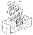
- Fig. 1 die Vorrichtung für die Bewegung der Ober- und Unterschenkel seitlich von vorn gesehen, teilweise geschnitten in perspektivisch schematischer Darstellung und
- Fig. 2 eine andere Ausbildungsform der Vorrichtung zur Bewegung des Oberkörpers, ebenfalls teilweise geschnitten seitlich von hinten gesehen in perspektivisch-schematischer Darstellung und
- Fig. 3 eine zusäzliche Ausbildungsform.
- Fig. 1 shows the device for the movement of the upper and lower legs seen from the side, partly in a perspective schematic representation and
- Fig. 2 shows another embodiment of the device for moving the upper body, also partially cut laterally seen from behind in a perspective-schematic representation and
- Fig. 3 shows an additional form of training.
Wie aus Fig. 1 ersichtlich, ist in dem Behandlungsgestell 1 ein wannenförmiger Tragrahmen 2 fest mit einer Schwenkachse 3 verbunden, die bei 4 in dem Behandlungsgestell gelagert ist. Die Achse 3 weist ebenfalls fest mit ihr verbundene radiale Ansatzhebel 5 und 6 auf, auf deren freien Enden Übertragungsrollen 7 und 8 lagern. Diese Übertragungsrollen 7 und 8 rollen auf dem Außenumfang von Exzenterscheiben 9 und 10 ab, die auf den Abtriebswellen 11 und 12 eines an den im Behandlungsgestell 1 angeordneten Gleichstrommotor 13 angeflanschten Getriebes 14 sitzen. Der wannenförmige Tragrahmen 2 trägt, hier für die Ober- und Unterschenkel der nicht dargestellten Benutzerperson bestimmte Auflagepolster 15, die auf nicht dargestellte Weise in Richtung des eingezeichneten Doppelpfeils S auf diesem verschiebbar gelagert sind, wobei der Verschiebeweg durch, ebenfalls nicht dargestellte Wegbegrenzungsanschläge begrenzt ist; die mögliche Verschiebung des Auflagepolsters 15 in Richtung von der Achse 3 weg ist strichpunktiert angedeutet.As can be seen from FIG. 1, a trough-shaped support frame 2 is fixedly connected to a pivot axis 3 in the treatment frame 1, which is mounted at 4 in the treatment frame. The axis 3 also has fixedly connected radial shoulder levers 5 and 6, on the free ends of which transfer rollers 7 and 8 are supported. These transfer rollers 7 and 8 roll on the outer circumference of
Bei der Ausbildung nach Fig. 2 ist der Tragrahmen 22 ebenfalls mit einer fest bei 24 im Behandlungsgestell 1 gelagerten Achse 23 verbunden. Das hier für den Oberkörper bestimmte Auflagepolster 35 ist auf dem Tragrahmen 22 in Richtung des eingezeichneten Doppelpfeils S in parallelen Schienen 36 aus der in vollen Linien gezeichneten Lage bis in die in unterbrochenen Linien angedeutete Lage längsverschiebbar. Die Ausbalancierung des Gewichtes des Auflagepolsters 35 erfolgt über ein bei 38 mit dem Auflagepolster 35 verbundenes, über Umlenkrollen 40, 41 und 42 geführtes Zugseil, das in Richtung des eingezeichneten Pfeiles bspw. durch ein nicht dargestelltes Gewicht oder eine Feder, zugbelastet ist. Der Motor 33 treibt über ein angeflanschtes Getriebe 34 und den Querabtrieb 44 und einen auf diesem sitzenden Hebel 39 eine Kurbelstange 43 an, die an einen radialen Ansatzhebel 25 angelenkt ist, der fest mit der Achse 23 verbunden ist.In the embodiment according to FIG. 2, the
Das Rahmengestell 51 (vgl. Fig. 3) weist einen rechteckigen Bodenrahmen 51a auf, der hier auf einem Querträgerpaar51b und Sockelfüßen 51c mit Tragplatte 51d einen Antriebsmotor 52 mit angeflanschtem Getriebe 53 sowie eine mit diesem gekuppelte Lenkermechanik 54 trägt, die das mit 55 bezeichnete Körperauflageelement in Bewegung versetzt. Dieses Körperauflageelement 55 ist seinerseits um eine Achse 56 bewegbar, die in Lagern 56a ebenfalls auf Stützen 51e im Rahmengestell 51 lagert. Der Bodenrahmen 51a steht mit Standfüßen 57, die wie angeduetet höhenverstellbar sind, auf dem Boden auf.The frame 51 (cf. FIG. 3) has a
Das mit 58 strichpunktiert angedeutete selbsttragende Gehäuse 58 weist hier ebenfalls einen rechteckigen Bodenrahmen 58a auf. der im Abstand 51b von dem Bodenrahmen 51a des Rahmengestells 51 angeordnet ist und mit eigenen, ebenfalls höhenverstellbaren Standfüßen 59 auf dem Boden aufsteht. Der Bodenrahmen 8a des selbsttragenden Gehäuses 58 umschließt den Bodenrahmen 51a des Rahmengestells 51 mit dem erwähnten Abstand 51b. Beide Bodenrahmen 51a und 58a weisen eine Mehrzahl von Laschenansätzen 40 bzw. 41 mit nach oben offenen Ausnehmungen 40a bzw. 41a auf, in die Befestigungsbolzen 42 einbringbar sind, mit denen die zwischen beiden Bodenrahmen 51a und 58a einsetzbare elastische Pufferelemente 43 lösbar befestigt werden können.The self-supporting
Claims (12)
dadurch gekennzeichnet,
daß die Auflageelemente (15, 35) zwischen Wegbegrenzungsanschlägen längsverschiebbar auf in dem Behandlungsgestell (1) schwenk- bzw. heb- und senkbaren Tragrahmen (2, 22) angeordnet sind.1. Body training device for articulating movement of body sections by means of support and / or support elements which can be pivoted and / or raised and lowered in a treatment rack and which can be driven by motors via interposed steering gears.
characterized,
that the support elements (15, 35) are arranged between displacement limit stops so as to be longitudinally displaceable on support frames (2, 22) which can be pivoted or raised and lowered in the treatment frame (1).
gekennzeichnet durch
an den Tragrahmen (2, 22) oder dem Behandlungsgestell (1) angeordnete, mit den Auflageelementen (15, 35) verbundenen, diese in einer und/oder beiden Verschieberichtungen elastisch oder zug- bzw. druckbeaufschlagende Rückholvorrichtungen.2. body exerciser according to claim 1,
marked by
on the support frame (2, 22) or the treatment frame (1), connected to the support elements (15, 35), these in one and / or both shifting directions elastic or pulling or pushing return devices.
dadurch gekennzeichnet,
daß die Rückholvorrichtungen aus an sich bekannten, stoßdämpfenden Gasfedern bestehen.3. body exerciser according to claim 2,
characterized,
that the return devices consist of known, shock-absorbing gas springs.
dadurch gekennzeichnet,
daß die Rückholvorrichtungen aus an sich bekannten Zuggewichten mit Seilumführungen (37, 40, 41, 42) bestehen.4. body exerciser according to claim 2,
characterized,
that the return devices consist of known pull weights with rope guides (37, 40, 41, 42).
dadurch gekennzeichnet,
daß die Tragrahmen (2, 22) eine im Behandlungsgestell (1) gelagerte feste Achse (3, 23) mit radialen Ansatzhebeln (5, 25) aufweisen, die über angelenkte Kurbelstangen (43) oder mittels auf Exzenterscheiben (9) geführten Übertragungsrollen (7) mit dem im Behandlungsgestell (1) angeordneten Antriebsmotor (13, 33) verbunden sind.5. body training device according to one or more of claims 1 to 4,
characterized,
that the support frames (2, 22) have a fixed axle (3, 23) mounted in the treatment frame (1) with radial extension levers (5, 25), which are connected via articulated crank rods (43) or by means of transfer rollers (7) guided on eccentric discs (9) ) are connected to the drive motor (13, 33) arranged in the treatment rack (1).
dadurch gekennzeichnet,
daß der Antriebsmotor (3) 33) als Getriebemotor mit einem oder zwei Querabtrieben (44 bzw. 11, 12) ausgebildet ist.6. body exerciser according to claim 5,
characterized,
that the drive motor (3) 33) is designed as a geared motor with one or two transverse drives (44 or 11, 12).
dadurch gekennzeichnet,
daß der Antriebsmotor (13, 33) ein regelbarer Gleichstrommotor ist.7. body training device according to claims 1, 5 and / or 6,
characterized,
that the drive motor (13, 33) is a controllable DC motor.
gekennzeichnet durch
eine Steuer- und Regeleinrichtung, die den Gleichstrommotor (13, 33) so steuert, daß dieser nach Ablauf einer festlegbaren Zeit bzw. nach Eingabe eines Abschaltbefehls mit einer festgelegten Drehzahl das Einfahren des Tragrahmens (2, 22) in eine vorgewählte Position bewirkt.8. body exerciser according to claim 7,
marked by
a control and regulating device which controls the direct current motor (13, 33) in such a way that it causes the support frame (2, 22) to be retracted into a preselected position after a definable time or after a shutdown command has been entered at a specified speed.
dadurch gekennzeichnet,
daß der Schwenkwinkel bzw. der Hub-Senkweg der Tragrahmen (2, 22) veränder- und festlegbar ist.9. body training device according to one or more of claims 1 to 8,
characterized,
that the swivel angle or the lifting-lowering path of the support frame (2, 22) can be changed and fixed.
dadurch gekennzeichnet,
daß die Körperauflageelemente (55) mit den Antriebsmotoren (52) sowie den zugehörigen Übertragungs- und ggfs. Steuereinrichtungen (53,54) in einem Rahmengestell (51) angeordnet sind, das frei auf dem Boden aufstehend mit Abstand (d) von einem selbständigen, ebenfalls frei auf dem Boden aufstehenden selbsttragend ausgebildeten Gehäuse (58) umschlossen und mit diesem lösbar durch vibrationsfreie Kuppelelemente (40,41,42,43) verbunden ist.10 body training device according to one or more of claims 1-9
characterized,
that the body support elements (55) with the drive motors (52) and the associated transmission and possibly control devices (53, 54) are arranged in a frame (51) which stands freely on the floor at a distance (d) from an independent, also freely standing on the floor self-supporting housing (58) and releasably connected to this by vibration-free coupling elements (40,41,42,43).
dadurch gekennzeichnet,
daß das Rahmengestell (51) und das selbsttragende Gehäuse (58) jeweils eigene an sich bekannte höhenverstellbare elastische Standfüße (57 bzw. 59) aufweisen.11 body exerciser according to claim 10
characterized,
that the frame (51) and the self-supporting housing (58) each have their own height-adjustable elastic feet (57 and 59) which are known per se.
dadurch gekennzeichnet,
daß das Rahmengestell (51) einen, vorzugsweise rechteckigen, Bodenrahmen (51a) aufweist, der mit Abstand (b) von einem entsprechenden dem selbsttragenden Gehäuse (58) zugeordneten Bodenrahmen (58a) umschlossen wird, wobei benachbarte Abschnitte beider Rahmen (51a,58a) Laschenansätze (40) (41) mit nach oben offenen Ausnehmungen (40a) 11a) zur Aufnahme von Befestigungsbolzen (42) von zwischen beiden Laschenansätzen (40; 41) anzuordnender an sich bekannter elastischer Pufferelemente (43) aufweisen.12 body training device according to claims 10 and / or 11,
characterized,
that the frame (51) has a, preferably rectangular, floor frame (51a), which is enclosed at a distance (b) by a corresponding floor frame (58a) assigned to the self-supporting housing (58), adjacent sections of both frames (51a, 58a) Have tabs (40) (41) with upwardly open recesses (40a) 11a) for receiving fastening bolts (42) of known elastic buffer elements (43) to be arranged between the two tabs (40; 41).
Applications Claiming Priority (4)
| Application Number | Priority Date | Filing Date | Title |
|---|---|---|---|
| DE3733795 | 1987-10-07 | ||
| DE19873733795 DE3733795A1 (en) | 1987-10-07 | 1987-10-07 | Physical exercising device for the controlled joint movement of body parts |
| DE8802519U | 1988-02-26 | ||
| DE8802519U DE8802519U1 (en) | 1988-02-26 | 1988-02-26 |
Publications (2)
| Publication Number | Publication Date |
|---|---|
| EP0311073A2 true EP0311073A2 (en) | 1989-04-12 |
| EP0311073A3 EP0311073A3 (en) | 1989-10-04 |
Family
ID=25860538
Family Applications (1)
| Application Number | Title | Priority Date | Filing Date |
|---|---|---|---|
| EP88116566A Withdrawn EP0311073A3 (en) | 1987-10-07 | 1988-10-06 | Exercise device for the controlled actuation of body joints |
Country Status (1)
| Country | Link |
|---|---|
| EP (1) | EP0311073A3 (en) |
Citations (6)
| Publication number | Priority date | Publication date | Assignee | Title |
|---|---|---|---|---|
| AT380395B (en) * | 1984-11-05 | 1986-05-12 | Gerhard Ing Hengl | MASSAGE DEVICE FOR THE LOWER EXTREMITIES |
| DE3602166A1 (en) * | 1985-01-23 | 1986-07-24 | Invacare Corp., Elyria, Ohio | MOTION EXERCISE DEVICE |
| EP0190086A1 (en) * | 1985-01-17 | 1986-08-06 | COMPAGNIE GENERALE DE MATERIEL ORTHOPEDIQUE Société Anonyme: | Apparatus for the mobilization of a lower limb |
| WO1986005699A1 (en) * | 1985-04-03 | 1986-10-09 | David John Piper | Exercise machine |
| DE3521470A1 (en) * | 1985-06-14 | 1987-02-05 | Baehr Heinz | MOTION RAIL |
| EP0230218A1 (en) * | 1986-01-21 | 1987-07-29 | Harald Sövegjarto | Device for support and movement of a patient's leg |
-
1988
- 1988-10-06 EP EP88116566A patent/EP0311073A3/en not_active Withdrawn
Patent Citations (6)
| Publication number | Priority date | Publication date | Assignee | Title |
|---|---|---|---|---|
| AT380395B (en) * | 1984-11-05 | 1986-05-12 | Gerhard Ing Hengl | MASSAGE DEVICE FOR THE LOWER EXTREMITIES |
| EP0190086A1 (en) * | 1985-01-17 | 1986-08-06 | COMPAGNIE GENERALE DE MATERIEL ORTHOPEDIQUE Société Anonyme: | Apparatus for the mobilization of a lower limb |
| DE3602166A1 (en) * | 1985-01-23 | 1986-07-24 | Invacare Corp., Elyria, Ohio | MOTION EXERCISE DEVICE |
| WO1986005699A1 (en) * | 1985-04-03 | 1986-10-09 | David John Piper | Exercise machine |
| DE3521470A1 (en) * | 1985-06-14 | 1987-02-05 | Baehr Heinz | MOTION RAIL |
| EP0230218A1 (en) * | 1986-01-21 | 1987-07-29 | Harald Sövegjarto | Device for support and movement of a patient's leg |
Non-Patent Citations (1)
| Title |
|---|
| SOVIET INVENTIONS ILLUSTRATED,Sektionen P,Q, Woche E18/82, 16. Juni 1982 Derwent Publications LTD., London, P33 * |
Also Published As
| Publication number | Publication date |
|---|---|
| EP0311073A3 (en) | 1989-10-04 |
Similar Documents
| Publication | Publication Date | Title |
|---|---|---|
| EP2435008B1 (en) | Device for therapeutically treating and/or training the lower extremities of a person | |
| DE1478056A1 (en) | Procedure for muscle training and equipment for carrying out the procedure | |
| DE102009049161A1 (en) | Work and assembly table | |
| DE2251808B2 (en) | DENTAL PATIENT CHAIR WITH PARALLELOGRAM CARRYING ARM | |
| DE60208657T2 (en) | DEVICE FOR MUSCLE RELAXATION | |
| EP1098684B1 (en) | Fitness apparatus | |
| DE3819276A1 (en) | BODY TRAINING DEVICE FOR TRAINING THE MUSCULAR | |
| DE3037619A1 (en) | Bedridden patient leg-exercising instrument - comprises tilting footrest on support subjected to tension load | |
| DE202008012420U1 (en) | Training device with at least two bewegungsverkoppelten or bewegungsverkoppelbaren gripping elements | |
| DE102006002548A1 (en) | Muscle training apparatus has rotatable shaft with handles mounted spatially separated from damping element on frame with gearing to transfer manual rotation of shaft to weights or similar | |
| EP0311073A2 (en) | Exercise device for the controlled actuation of body joints | |
| EP0561106A2 (en) | Apparatus for carrying out passive exercise | |
| EP1654956B1 (en) | Standing aid device for rehabilitation of body impaired persons | |
| DE3532445A1 (en) | Training apparatus | |
| DE3733795A1 (en) | Physical exercising device for the controlled joint movement of body parts | |
| EP3380054B1 (en) | Training apparatus and method | |
| WO1993025283A1 (en) | Muscle training device | |
| DE2836134A1 (en) | Height adjustment for working table esp. drawing board - consists of pulley, spring and two rollers inside cross-beam between two uprights | |
| WO1993024190A1 (en) | Muscle training device | |
| DE1174227B (en) | Exercise machine for performing active and passive movements of the body | |
| EP2127626B1 (en) | Training device with at least two motion-coupled or motion-coupled gripping elements | |
| DE3800496C2 (en) | ||
| DE3814559C2 (en) | ||
| DE10316688B4 (en) | Device used for training/therapy comprises two stand surfaces provided on independently mounted stand surface elements pivoted in opposite directions by a motor drive about two perpendicular axes lying in the plane of each stand surface | |
| DE8533045U1 (en) | Exercise device |
Legal Events
| Date | Code | Title | Description |
|---|---|---|---|
| PUAI | Public reference made under article 153(3) epc to a published international application that has entered the european phase |
Free format text: ORIGINAL CODE: 0009012 |
|
| AK | Designated contracting states |
Kind code of ref document: A2 Designated state(s): BE FR IT NL SE |
|
| PUAL | Search report despatched |
Free format text: ORIGINAL CODE: 0009013 |
|
| AK | Designated contracting states |
Kind code of ref document: A3 Designated state(s): BE FR IT NL SE |
|
| STAA | Information on the status of an ep patent application or granted ep patent |
Free format text: STATUS: THE APPLICATION IS DEEMED TO BE WITHDRAWN |
|
| 18D | Application deemed to be withdrawn |
Effective date: 19900405 |